US1317543A - Planooraph co - Google Patents
Planooraph co Download PDFInfo
- Publication number
- US1317543A US1317543A US1317543DA US1317543A US 1317543 A US1317543 A US 1317543A US 1317543D A US1317543D A US 1317543DA US 1317543 A US1317543 A US 1317543A
- Authority
- US
- United States
- Prior art keywords
- piece
- leg
- knee
- socket
- artificial
- Prior art date
- Legal status (The legal status is an assumption and is not a legal conclusion. Google has not performed a legal analysis and makes no representation as to the accuracy of the status listed.)
- Expired - Lifetime
Links
- 210000002414 leg Anatomy 0.000 description 13
- 210000003127 knee Anatomy 0.000 description 10
- 241000272201 Columbiformes Species 0.000 description 2
- 210000000689 upper leg Anatomy 0.000 description 2
- 238000004140 cleaning Methods 0.000 description 1
- 210000003414 extremity Anatomy 0.000 description 1
- 210000000629 knee joint Anatomy 0.000 description 1
- 230000003014 reinforcing effect Effects 0.000 description 1
Images
Classifications
-
- A—HUMAN NECESSITIES
- A61—MEDICAL OR VETERINARY SCIENCE; HYGIENE
- A61F—FILTERS IMPLANTABLE INTO BLOOD VESSELS; PROSTHESES; DEVICES PROVIDING PATENCY TO, OR PREVENTING COLLAPSING OF, TUBULAR STRUCTURES OF THE BODY, e.g. STENTS; ORTHOPAEDIC, NURSING OR CONTRACEPTIVE DEVICES; FOMENTATION; TREATMENT OR PROTECTION OF EYES OR EARS; BANDAGES, DRESSINGS OR ABSORBENT PADS; FIRST-AID KITS
- A61F2/00—Filters implantable into blood vessels; Prostheses, i.e. artificial substitutes or replacements for parts of the body; Appliances for connecting them with the body; Devices providing patency to, or preventing collapsing of, tubular structures of the body, e.g. stents
- A61F2/50—Prostheses not implantable in the body
- A61F2/60—Artificial legs or feet or parts thereof
- A61F2/64—Knee joints
Definitions
- the hereindescribed artificial leg is intended for use Where the leg has been amputated above the knee, and the said invention is intended to provide a cheap, simple and effective appliance to replace, as far as practicable, the lost limb of the wearer.
- Fig. 2 shows a side elevation of the same.
- Fig. 3 is a similar view to Fig. 2, except that the upper part of the leg is shown .in central vertical section.
- Fig. at is a perspective view of the blank used to form the upper portion or seat of the socket member.
- Fig. 5 shows the various component parts of the knee joint.
- a represents the annular reinforcing member of the socket b, which part a is sometimes known as the seat or bearing which engages the upper portion of the amputated leg.
- This member a' is provided with a groove a into which the upper end of the socket member 79 engages.
- This socket member may be made of any suitable material, such as fibroleum, which is shaped to the desired form in any well known or convenient way.
- the members a and b are to be permanently connected together they may be cemented together; but if it is desired to replace either member, due to wear or other causes, the two may be sewed together as by thread or wire stitches a It will be obvious that other suitable means for attaching the two together may be adopted if desired.
- the knee portion comprises two cheek members 0 and e, and an intermediate member d, which are cemented or otherwise secured together in any'convenient way, and
- the center member d'of the knee piece is provided with a shoulder d, below which I provide a resilient pad d which is adapted to engage the shoulder f of the lower leg member f, which is pivoted to the knee piece by means of the pivot pin 9, which passes through the lower leg member f and through the center piece d and cheek members 0 and c of the knee piece.
- the lower leg member may be provided with any suitable artificial foot, resilient or otherwise, but this not being a part of my present invention will not be herein described.
- the socket b is slipped over the stump of the wearer, with or without such wrappings on the stump as may be needed. It is then secured in place in any convenient way, which securing means, not being a part of my present invention, will not be further described herein.
- the forward movement of the socket b will lift the lower leg member from the ground, and a forward swinging movement will be imparted to such member, so that the lower leg member will'swing out to the proper position for engaging the ground when the other foot is lifted; while as the body of the wearer advances the artificial knee member will remain sufliciently rigid until a step is made in advance by the sound leg, and the artificial leg will bend at the proper time after the forward step of the sound leg has been completed and it is desired to swing the artificial leg forward for another step.
- the knee member coacting with the lower leg member permits an exceeding simple joint which permits the free swing back of the lower leg member when desired; and I provide a stiff structure against the toppling over of the wearer and which does not require any spring return arrangement. Furthermore, it is seen that by having the member a detachable, it may be readily removed for cleaning purposes, or to replace worn parts.
Landscapes
- Health & Medical Sciences (AREA)
- Transplantation (AREA)
- Biomedical Technology (AREA)
- Cardiology (AREA)
- Oral & Maxillofacial Surgery (AREA)
- Engineering & Computer Science (AREA)
- Orthopedic Medicine & Surgery (AREA)
- Heart & Thoracic Surgery (AREA)
- Vascular Medicine (AREA)
- Life Sciences & Earth Sciences (AREA)
- Animal Behavior & Ethology (AREA)
- General Health & Medical Sciences (AREA)
- Public Health (AREA)
- Veterinary Medicine (AREA)
- Orthopedics, Nursing, And Contraception (AREA)
Description
E. 1'. A. BOULANGER.
ARTlFlCIAL LEG.
APPLICATION FILED FEB. 16. 1918.
1,3 1 7,543, Patented Sept. 30, 1919.
I ITwHZET! Erhri' I 1%. Paula-L967. Z M m ERNEST JOSEPH AIMABLE BOULANGER, OF COLOMBES, FRANCE.
, ARTIFICIAL LEG.
Specification of Letters Patent. Patented Sept. 30, 1919.
Application filed. February 16,1918. Serial No. 217,600?
To all whom it may concern:
Be it known that I, ERNEST J osnrn AIM- ABLE BOULANGER, orthopedist, a citizen of the Republic of France, formerly of 81 Rue Emile Zola, St. Quentin, Department Aisne, France, and at present 65 Rue des Champarons, Colombes, Department Seine, France, have invented new and useful Improvements in Artificial Legs, of which the following is a specification.
The hereindescribed artificial leg is intended for use Where the leg has been amputated above the knee, and the said invention is intended to provide a cheap, simple and effective appliance to replace, as far as practicable, the lost limb of the wearer.
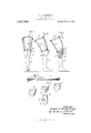
The invention will be more fully under-. stood after reference to the accompanying drawings, in which v Figure 1 shows a front elevation of the artificial leg.
Fig. 2 shows a side elevation of the same.
Fig. 3 is a similar view to Fig. 2, except that the upper part of the leg is shown .in central vertical section.
Fig. at is a perspective view of the blank used to form the upper portion or seat of the socket member; and
Fig. 5 shows the various component parts of the knee joint.
Similar reference letters indicate corresponding parts throughout the several views.
a represents the annular reinforcing member of the socket b, which part a is sometimes known as the seat or bearing which engages the upper portion of the amputated leg.
This member a'is provided with a groove a into which the upper end of the socket member 79 engages. This socket member may be made of any suitable material, such as fibroleum, which is shaped to the desired form in any well known or convenient way.
If the members a and b are to be permanently connected together they may be cemented together; but if it is desired to replace either member, due to wear or other causes, the two may be sewed together as by thread or wire stitches a It will be obvious that other suitable means for attaching the two together may be adopted if desired. v
The knee portion comprises two cheek members 0 and e, and an intermediate member d, which are cemented or otherwise secured together in any'convenient way, and
the same are connected to the socket piece Z) in any convenient way as by means of the band 6. The center member d'of the knee piece is provided with a shoulder d, below which I provide a resilient pad d which is adapted to engage the shoulder f of the lower leg member f, which is pivoted to the knee piece by means of the pivot pin 9, which passes through the lower leg member f and through the center piece d and cheek members 0 and c of the knee piece.
The lower leg member may be provided with any suitable artificial foot, resilient or otherwise, but this not being a part of my present invention will not be herein described.
In practice the socket b is slipped over the stump of the wearer, with or without such wrappings on the stump as may be needed. It is then secured in place in any convenient way, which securing means, not being a part of my present invention, will not be further described herein.
It will be seen that the forward movement of the socket b will lift the lower leg member from the ground, and a forward swinging movement will be imparted to such member, so that the lower leg member will'swing out to the proper position for engaging the ground when the other foot is lifted; while as the body of the wearer advances the artificial knee member will remain sufliciently rigid until a step is made in advance by the sound leg, and the artificial leg will bend at the proper time after the forward step of the sound leg has been completed and it is desired to swing the artificial leg forward for another step.
It will be seen that the knee member coacting with the lower leg member permits an exceeding simple joint which permits the free swing back of the lower leg member when desired; and I provide a stiff structure against the toppling over of the wearer and which does not require any spring return arrangement. Furthermore, it is seen that by having the member a detachable, it may be readily removed for cleaning purposes, or to replace worn parts.
Having thus described my invention what I claim and desire to secure by Letters Pat ent of the United States is 1. In an artificial leg, the combination with a socket piece for the thigh, and a shin piece, of a knee piece composed of a central member adapted to receive the head of said shin piece, and two side members, forming with a socket piece for the thigh, and a shin" piece, of a knee piece composed of a central member adapted to receive the head of said 10 shin piece, and tWo side members, forming w'vard upper edge, and the central member of said knee piece being provided with an abutment to engage saidshoulder, and a pivot pin passing through said side mem- "bers and the head of said shin piece and forming a pivot forsaid shin piece, substan- "tially as described.
ERNEST JOSEPH AIMABLE BOULANGER.;
Copies of this patent maylbe obtained for five cents each, by addressing the fdommissioner of Patents,
' Washington, D. G. v
Publications (1)
| Publication Number | Publication Date |
|---|---|
| US1317543A true US1317543A (en) | 1919-09-30 |
Family
ID=3385023
Family Applications (1)
| Application Number | Title | Priority Date | Filing Date |
|---|---|---|---|
| US1317543D Expired - Lifetime US1317543A (en) | Planooraph co |
Country Status (1)
| Country | Link |
|---|---|
| US (1) | US1317543A (en) |
-
0
- US US1317543D patent/US1317543A/en not_active Expired - Lifetime
Similar Documents
| Publication | Publication Date | Title |
|---|---|---|
| US53931A (en) | Improvement in artificial legs | |
| US2587166A (en) | Knee-supporting brace | |
| US56983A (en) | Improvement in artificial legs | |
| US1317543A (en) | Planooraph co | |
| US2618896A (en) | Jointed doll | |
| US2013068A (en) | Bunion brace | |
| US51593A (en) | Improvement in artificial legs | |
| US2804721A (en) | Joint structure for a doll limb | |
| US1283093A (en) | Artificial limb. | |
| US1216367A (en) | Artificial leg. | |
| US431797A (en) | Surgical brace | |
| US1479297A (en) | Artificial limb and harness therefor | |
| US1343297A (en) | Artificial limb | |
| US278566A (en) | Artificial leg | |
| US959881A (en) | Joint for artificial legs. | |
| US1365205A (en) | Fiber knee-control stop for above-knee amputations | |
| US1032074A (en) | Artificial leg. | |
| US55645A (en) | Improvement in artificial legs | |
| US1308816A (en) | Planoottapu co | |
| US492583A (en) | Artificial-leg attachment | |
| US1932216A (en) | Toy figure | |
| US2130271A (en) | Artificial foot | |
| US1383365A (en) | Artificial limb | |
| US1323444A (en) | Artificial leg. | |
| US563706A (en) | bo wma-n |