US1316632A - mokse - Google Patents
mokse Download PDFInfo
- Publication number
- US1316632A US1316632A US1316632DA US1316632A US 1316632 A US1316632 A US 1316632A US 1316632D A US1316632D A US 1316632DA US 1316632 A US1316632 A US 1316632A
- Authority
- US
- United States
- Prior art keywords
- buckle
- metal
- fingers
- sockets
- locking tongue
- Prior art date
- Legal status (The legal status is an assumption and is not a legal conclusion. Google has not performed a legal analysis and makes no representation as to the accuracy of the status listed.)
- Expired - Lifetime
Links
- 239000002184 metal Substances 0.000 description 30
- 238000003466 welding Methods 0.000 description 12
- 238000010276 construction Methods 0.000 description 8
- 229910000831 Steel Inorganic materials 0.000 description 6
- 239000010959 steel Substances 0.000 description 6
- 230000014759 maintenance of location Effects 0.000 description 4
- 241000905957 Channa melasoma Species 0.000 description 2
- 241000283220 Odobenus rosmarus Species 0.000 description 2
- 102000012152 Securin Human genes 0.000 description 2
- 108010061477 Securin Proteins 0.000 description 2
- 238000005452 bending Methods 0.000 description 2
- 238000005219 brazing Methods 0.000 description 2
- 230000002950 deficient Effects 0.000 description 2
- 230000001419 dependent Effects 0.000 description 2
- 238000003379 elimination reaction Methods 0.000 description 2
- 239000000463 material Substances 0.000 description 2
- 230000004048 modification Effects 0.000 description 2
- 238000006011 modification reaction Methods 0.000 description 2
- 239000002245 particle Substances 0.000 description 2
- 239000003247 radioactive fallout Substances 0.000 description 2
- 238000000926 separation method Methods 0.000 description 2
- 238000005476 soldering Methods 0.000 description 2
- XLYOFNOQVPJJNP-UHFFFAOYSA-N water Substances O XLYOFNOQVPJJNP-UHFFFAOYSA-N 0.000 description 2
Images
Classifications
-
- A—HUMAN NECESSITIES
- A43—FOOTWEAR
- A43C—FASTENINGS OR ATTACHMENTS OF FOOTWEAR; LACES IN GENERAL
- A43C11/00—Other fastenings specially adapted for shoes
- A43C11/14—Clamp fastenings, e.g. strap fastenings; Clamp-buckle fastenings; Fastenings with toggle levers
- A43C11/1406—Fastenings with toggle levers; Equipment therefor
-
- Y—GENERAL TAGGING OF NEW TECHNOLOGICAL DEVELOPMENTS; GENERAL TAGGING OF CROSS-SECTIONAL TECHNOLOGIES SPANNING OVER SEVERAL SECTIONS OF THE IPC; TECHNICAL SUBJECTS COVERED BY FORMER USPC CROSS-REFERENCE ART COLLECTIONS [XRACs] AND DIGESTS
- Y10—TECHNICAL SUBJECTS COVERED BY FORMER USPC
- Y10T—TECHNICAL SUBJECTS COVERED BY FORMER US CLASSIFICATION
- Y10T24/00—Buckles, buttons, clasps, etc.
- Y10T24/21—Strap tighteners
- Y10T24/2102—Cam lever and loop
- Y10T24/2142—Ski boot and garment fasteners
Description
W; R. MORSE.
BUCKLE.
APPLICATION FILED res. 11. I918.
Patented Sept. 23, 1919.
UNITED STATES PATENT OFFICE.
WALTER R. MORSE, OF WATER'BURY, CONNECTICUT, ASSIGNOIL TO THE SHOE HARD- WARE COMPANY, A CORPORATION OF CONNECTICUT.
BUCKLE.
Specification of Letters Patent.
Patented Sept. 23, 1919.
Application filed February 11, 1918. Serial Nazis-n58.
To all whom it may concern:
Be it known that I, WALTER R. MORSE, a citizen of the United States, residing at Waterbury, county of New Haven, and State of Connecticut, have invented certain new and useful Improvements in Buckles, of which the following is a full, clear, and exact description.
This invention relates to buckles, and more particularly to a novel method of forming and securing together the component parts of a buckle, and also to the buckle manufactured in. accordance with such method.
There have heretofore been used upon boots, shoes, arctics, and various other articles, buckles formed of two stampings of sheet metal, and comprising a socketed plate-member to which is hingedly secured a hook-shaped locking tongue. The platemember of such buckles is customarily formed at one end with three extensions or fingers suitably spaced apart, the outer two fingers being provided with alined sockets which receive the pintles of the locking tongue. The intermediately disposed finger acts as a spring and cooperates with a cam surface on the locking tongue to hold the tongue in opened and closed positions. The sockets in the two outer fingers are formed by striking up a portion of the metal intermediate the length of the fingers and bending back the ends of the fingers to overlie the recesses so formed. No provision has heretofore been made for securin the bent back ends to the portions of the ngers lying therebeneath, the retention of the ends in place being solely dependent upon the strength of the metal at the point of bend. This feature is objectionable for in turning back the ends a sharp bend is made placing the particles of metal at the point of bend under very great strain, which is frequently so severe that the metal splits or cracks with the result that when the ends are subjected to the additional strains caused by opening and closing the locking tongue, they often break off permitting the pintles of the tongue to fall out of the sockets, thus destroying the usefulness of the buckle. In order to guard against this disadvantage hi h grades of steel have been used, but the difficulty has never been entirely overcome. It has consequently been the practice to test each buckle by snapping the locking tongue to closed and opened positions, which additional precaution however, has not resulted in the complete elimination of defective buckles, as frequently the fracture at the point of bend does not manifest itself until after the buckle has been in use for a long period of time. The use of high grade steel and the cost of labor required to perform the snapping operations add greatly to the final cost of the buckle without entirely overcoming the liability of the buckle to break in service.
An object of the present invention, accordingly, is to provide an improved method whereby buckles free from the various disadvantages hereinbefore noted may be rapidly and economically manufactured.
A further object of the present invention is to provide a buckle of great durability, simple construction, and inexpensive manu' facture which will withstand without breakage the strains encountered in service.
Other objects of the invention will hereinafter appear.
In the accompanying drawings wherein some of the various possible embodiments of the invention are shown:
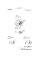
Figure 1 is a perspective view of a buckle constructed in accordance with my invention, the locking tongue being shown in opened position.
Fig. 2 is a side view ofthe buckle illustrated in Fig. 1.
Figs. 3 and 4 are fragmentary views illustrating modified forms of construction;
The buckle illustrated in the drawings comprises a plate-member 10 to which is hingedly secured a hook-shaped locking tongue 11. The pl2tl38111B11'1b61 and locking tongue are preferably made ofsheet steel, although it is to be understood that any suitable kind or grade of sheet metal may be used for the purpose. One end of the platemember is formed with an elongated eye 12 to provide a convenient means for attaching the buckle to any suitable article, while the other end is provided with three spaced fingers the outer two of which, 13, are
formed with sockets 14 which receive the pintles 15 of the locking tongue. The sockas set forth they are integrally united to a portion of the metal lying therebeneath by brazing, soldering, welding, or other suitable means. Any desired method of welding may be used preferably, however, the electric welding method is employed by which term I mean the well-known method in which the work is brought to the welding temperature by the internal heat generated by the resistance of the work to the passage of electric current at the place of contact between the parts to be joined by the welding pressure.
I11 Fig. 1 of the drawings the ends of the fingers are shown united to portions of the metal lying therebeneath by a line weld 18 extending longitudinally of the fingers and along the outer margins thereof. In Fig. 3 the weld 19 is shown extending transversely across the finger and longitudinally along the outer margin thereof. In Fig. 4 the weld 20 extends transverselyacross the finger. Although I have illustrated some of the various forms of welds which may be used, it is to be understood that the form and position of the weld may be greatly varied within the scope of the invention.
It is also to be understood that the sockets may be formed in various other ways than that set forth, for example, the fingers may be made with laterally extending portions adapted to be bent over to cover the recesses, or separate pieces of metal may be placed over the recesses and held in place by weld ing. In certain types of construction the recesses may be formed in the bent over portions of metal or both the bent over portions of metal and the portions lying therebeneath may be provided with registering recesses. In the embodiment of the invention illustrated in the drawing the recesses are shown disposed inwardly from the point of bend, which construction renders the strength of the sockets totally independent of the strength of the metal at the point of bend. If desired, however, the sockets may be formed at the point of bend in the usual and well-known manner.
The locking tongue 11 of the buckle consists of a hook-shaped stamping of metal and is provided with integrally formed ears or pintle pins 15 which fit into the sockets 14 of the plate-member 10 providing a hinge connection between the parts. The pintles are arranged inwardly from the bill of the hook and the portion of metal 21 lying therebeyond serves as a cam which cooperates with the resilient finger 22 formed on the plate-member intermediate the two socketed fingers 13 to hold the tongue in opened and closed position.
By my invention I am enabled to produce a more durable and satisfactory buckle than has heretofore been known. I am also enabled to produce such buckles at a lower cost than that of the previously known buckles by reason of the fact that less expensive grades of metal-maybe used, and the costly snapping operations are entirely dispensed with.
While I have described some of the preferred embodiments of my invention, it is to be understood that various modifications in form, material and arrangement may be made without departing from the spirit and scope of the invention as defined in the appended claim.
Having thus described my invention, what I claim as new and desire to protect by Letters Patent is:
A buckle comprising a tongue portion having pintles and a cam plate, and a metal body portion formed of a single sheet and bifurcated ends formed of double sheets havingportions spaced to form sockets for the retention of said pintles the upper sheets of said ends being integral with the body portion and'the lower sheets forming bearing surfaces for said pintles, and a spring plate above said cam and integral with the body portion adapted for spring pressed engagement with said cam, the said lower sheets being firmly united with the upper sheets throughout a portion of their surfaces to the rear of the free ends of said upper sheets for preventing separation of the sheets and for transmitting the pressure from the spring to said upper sheets when the tongue functions.
Signed at WVaterbury, Connecticut, this thirty-first day of January, 1918.
WALTER R. MORSE.
Copies of this patent may be obtained for five cents each, by addressing the Commissioner of Patents,
. Washington, I). 0.
Publications (1)
| Publication Number | Publication Date |
|---|---|
| US1316632A true US1316632A (en) | 1919-09-23 |
Family
ID=3384116
Family Applications (1)
| Application Number | Title | Priority Date | Filing Date |
|---|---|---|---|
| US1316632D Expired - Lifetime US1316632A (en) | mokse |
Country Status (1)
| Country | Link |
|---|---|
| US (1) | US1316632A (en) |
Cited By (1)
| Publication number | Priority date | Publication date | Assignee | Title |
|---|---|---|---|---|
| US2832076A (en) * | 1953-04-10 | 1958-04-29 | Polachek | Bow tie clip |
-
0
- US US1316632D patent/US1316632A/en not_active Expired - Lifetime
Cited By (1)
| Publication number | Priority date | Publication date | Assignee | Title |
|---|---|---|---|---|
| US2832076A (en) * | 1953-04-10 | 1958-04-29 | Polachek | Bow tie clip |
Similar Documents
| Publication | Publication Date | Title |
|---|---|---|
| US1316632A (en) | mokse | |
| US1149444A (en) | Necktie-clip. | |
| US1061032A (en) | Hasp-fastener. | |
| US1081501A (en) | Clasp. | |
| US983404A (en) | Snap-hock. | |
| US502529A (en) | Harry s | |
| US2105689A (en) | Coupling device for flexible members | |
| US954216A (en) | Snap-hook. | |
| US1454468A (en) | Belt loop | |
| US1892422A (en) | Clasp | |
| US1086657A (en) | Pin-joint. | |
| US380951A (en) | Garment-clasp | |
| US462143A (en) | Boley | |
| US951555A (en) | Clip for drive-chains. | |
| US500437A (en) | Garment-supporter | |
| US523465A (en) | Buckle | |
| US1474168A (en) | Shoe clasp | |
| US1275265A (en) | Chain-fastener. | |
| US1157757A (en) | Snap-hook. | |
| US704111A (en) | Cuff-holder. | |
| US1346979A (en) | Buckle | |
| US350055A (en) | Assffinoe to w | |
| US756607A (en) | Snap-hook. | |
| US820703A (en) | Snap-hook. | |
| US244071A (en) | Samuel moore |