US1315744A - Depositotg-kachbte - Google Patents
Depositotg-kachbte Download PDFInfo
- Publication number
- US1315744A US1315744A US1315744DA US1315744A US 1315744 A US1315744 A US 1315744A US 1315744D A US1315744D A US 1315744DA US 1315744 A US1315744 A US 1315744A
- Authority
- US
- United States
- Prior art keywords
- nozzles
- forcing
- valve
- bar
- nozzle
- Prior art date
- Legal status (The legal status is an assumption and is not a legal conclusion. Google has not performed a legal analysis and makes no representation as to the accuracy of the status listed.)
- Expired - Lifetime
Links
- 230000007246 mechanism Effects 0.000 description 21
- 238000000151 deposition Methods 0.000 description 12
- 239000011435 rock Substances 0.000 description 12
- 238000005266 casting Methods 0.000 description 6
- IJJWOSAXNHWBPR-HUBLWGQQSA-N 5-[(3as,4s,6ar)-2-oxo-1,3,3a,4,6,6a-hexahydrothieno[3,4-d]imidazol-4-yl]-n-(6-hydrazinyl-6-oxohexyl)pentanamide Chemical compound N1C(=O)N[C@@H]2[C@H](CCCCC(=O)NCCCCCC(=O)NN)SC[C@@H]21 IJJWOSAXNHWBPR-HUBLWGQQSA-N 0.000 description 3
- 238000004140 cleaning Methods 0.000 description 3
- 238000010276 construction Methods 0.000 description 3
- 235000015110 jellies Nutrition 0.000 description 3
- 239000008274 jelly Substances 0.000 description 3
- 241001307241 Althaea Species 0.000 description 2
- 235000006576 Althaea officinalis Nutrition 0.000 description 2
- 230000009471 action Effects 0.000 description 2
- 235000019219 chocolate Nutrition 0.000 description 2
- 235000009508 confectionery Nutrition 0.000 description 2
- 235000001035 marshmallow Nutrition 0.000 description 2
- 239000002184 metal Substances 0.000 description 2
- 238000005192 partition Methods 0.000 description 2
- 241000239290 Araneae Species 0.000 description 1
- 241000543381 Cliftonia monophylla Species 0.000 description 1
- 241000183024 Populus tremula Species 0.000 description 1
- 241001274197 Scatophagus argus Species 0.000 description 1
- 238000004519 manufacturing process Methods 0.000 description 1
- 239000000463 material Substances 0.000 description 1
- 230000004048 modification Effects 0.000 description 1
- 238000012986 modification Methods 0.000 description 1
- 229920000136 polysorbate Polymers 0.000 description 1
Images

Classifications
-
- B—PERFORMING OPERATIONS; TRANSPORTING
- B65—CONVEYING; PACKING; STORING; HANDLING THIN OR FILAMENTARY MATERIAL
- B65D—CONTAINERS FOR STORAGE OR TRANSPORT OF ARTICLES OR MATERIALS, e.g. BAGS, BARRELS, BOTTLES, BOXES, CANS, CARTONS, CRATES, DRUMS, JARS, TANKS, HOPPERS, FORWARDING CONTAINERS; ACCESSORIES, CLOSURES, OR FITTINGS THEREFOR; PACKAGING ELEMENTS; PACKAGES
- B65D81/00—Containers, packaging elements, or packages, for contents presenting particular transport or storage problems, or adapted to be used for non-packaging purposes after removal of contents
- B65D81/32—Containers, packaging elements, or packages, for contents presenting particular transport or storage problems, or adapted to be used for non-packaging purposes after removal of contents for packaging two or more different materials which must be maintained separate prior to use in admixture
- B65D81/3216—Rigid containers disposed one within the other
- B65D81/3222—Rigid containers disposed one within the other with additional means facilitating admixture
Definitions
- My present invention is intended to be applied to and form a part of a depositing' machine of the general construction shown in my pending,r application No'. 834,780, filed April- 27th,'1914t, and more particularly relates to modifications and improvements connected with the nozzles of the depositing' mechanism of the machine. it has been .found that with some'fornis of concentric double nozzles heretofore employed, espe cially 'those in which the annular opening);
- My invention consists in the combination and organizan tion of cooperating parts constituting such mechanism, the essential elements of which. are particiiilarly pointed out in the appended claims.
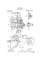
- Figure l is a side View of a portion of the hoppers and adjacent portions of a depositingl machine to which my invention is applied;
- Fig'. Q is a cross sec tion of the nozzle bar on a larger scale taken centrally through one of the double depos itingI nozzles and longitudinally of the machine;
- lfig. 3 is a plan view of the nozzle bar, the top member being"partlylbioken away to disclose underlyingparts of the stri'lcture;
- Fig'. fl a vertical section taken longitudinally of the nozzle-bar, partly broken away to show the cleaning member in elevation;
- Fig. 5 is a perspective of the cleaning member detached; and
- casting' 3 beine formed with a bach "Wall and side Walls (3 to which is secured a sheet 'metal plate 'l' to malte. up the lai er or marshmallow hopper lli., and 'the ca ig Ll: being formed with a bach' wall il and side ivalls 9 to which is scoured a shear-,t metal plate l0 to malte up the smaller or jelly hopper B.
- flllic lciver parte of the side Walls of the tivo castinns moet to .forni a tight joint, and externally are formed with incetinna vertical flanges l1 by which they are bolted together, but the bach' Walls are offset or separated from each other Ato lcaie a rectanffnlar space lying; between such walls and the extended portions of the side Walls, which space is divided by a partition plato l2 into tivo piston chambc s for the rcception of the rectangular pistons or plunger-s of the forcing' mechanism.
- the partition plate l2 seated in grooves formed in the 'astnpl1 si.
- the bases of the castings are suitably sccuredto the frame of the machine, and the hoppers A and B respectively communicate Withthe adjacent forcing chambers through long inlet ports 18 and lll: respectively opening into the associated forcing chan'ibers near the bottom of each. rlhe larger forcing chamber is closed at its top titi 'by a rectangular piston 14 and a thinner rectangular supply valve governing the port 13, and the smaller forcing chamber is closed by a correspondingpiston 16 and supply valve 17.
- a rectangular plate 18 forming a shut-off valve is arranged to reciprocate horizontally in a slideway formed in the casting 3, and a similar shut-oil" valve 19 is provided in the casting l.
- the nozzlear or nozzle-carryport, and thc-shut-off valve being in outerbolted thereto, the upper bar being formed' 'most position.
- the-supply valve returns to close'the inlet port in advance of the downward forcing stroke of the main piston, the shut-off valve also shifting to open or outerposition.
- the nozzle bar preferably is formed of an upper bar 20 fitting the dovetail scat at the bottom ofVv the-castings 3 and 4 and a lower bar 21 with slots 22 at one end and bolt holes 23 at the other-*whereby it may bebolted to the hopper structure.
- the upper bar is equipped withl a series of depending nozzles 24 which by means of theshut-off valve 1S are intermittently placed in free coniinnnica-tion with the larger oz marshmallow forcing chamber- ⁇ as above described.
- the lower bar has secured to it a corresponding series of ynozzles 25 eoncentrically surroundving the nozzles 24, and the lower and upper bars have their meeting faces longitudinally i recessed around the nozzles 24 to form spaces between the nozzles 24 and 25,which spaces l connect with passages 2G formed in the np per bar 20 and terminatingr in ports which are governed by the shut-oif valve 19 of f the jelly or chocolate forcing mechanism.
- the cleaner members consist each of a reciprocating grooved sleeve 27 surrounding a cylindrical section of the associated nozarms 28 with a 4rinor 29 which surrounds the cylindrical lowermost portion of the nozzle 2l] 'These cleaner members are supported and reciprocated. in unison through a rock shaft 30 journaled in a bearing formed onehalf in the upper bar 20 and onehalf in the lower bar 21 and equipped with pairs of pins 31-31 which engage opposite sides of the groove in the sleeve 27 of the cleaner members, the tw i bars being recessed above and below the p is sufficiently toV permit the movement given them bythe rocking of the shaft.
- the shaft 30 may conveniently be oscillated by -means of a rock arm 32 which by a link 33 is connected to a second-'rock arm' 34C by means of which the shut-olf valve 19 is also operated.
- the rock arm 34 constitutes a part ,of the connections described in my prior application before mentioned for operating said shut-ofi' valve, siiclrconnections including a grooved cam 50 fixed to a rotating shaft'51 and arranged to coperate with a roller 52 carried by a rocking lever 53, which lever, through a pivoted connecting rod 54 rocks a crank 55 fasten a rock shaft 56, which shaft at one end carries the rock arin 34 above mentioned and at its opposite end ⁇ a similar arm, the two arms being pivoted to the opposite ends ofl the shut-olf y valve.
- the arrangement and adjustment ofthe parts is such that during the depositing action of the smaller forcing mechanism the cleaner members are in uppermost position,
- shut-oli valve remains openand the cleaner member in upper position until the upward movement of the main plunger ,16 has broken the flow of confection and sucked the material upwardly a short distance in the nozzles, shortly above the position then zie 24 and connected by a pairvof depending occupied by the rings 29, upon which the".
- shut-off valve closes and the clcanermenibers ymove downwardly to clean out the. aunular openings between the outer and inner nozzles. l/Vlien the shut-off valve uncovers .the ports 26, the cleanermembers are again elevated to permit a succeeding depositing action to take place.
- the cleaner member should be reciprocated be tween every depositing operation, since a reeiprocation every alternate operation, or at longer intervals, may be sufficient for practical purposes.
- the cleaner ring acts most efficiently in crushing and dislodging obstructions when it substantially fills
- the annular opening' between the nozzles (although a ⁇ somewhat loose fit desirable and preferable), yet it will fulfil its functions .satisfactorily and successfully when reduced, iii size so' that a considerable clearance is left on each side of the ring, as clearly shown in Fig. 6, which illustrates such a modified construction.
- cleaner mechanism comprising a sliding member formed with an upper tubular portion and depending arms and a terminal ring arranged within said orifice with saidA ring disposed above the outlet thereof, and means for reciprocating said member to shift said ring to and from said outlet during the interva'ls of rest between the operations ofthe forcing mechanism.
- cleaner ⁇ mechanism comprising aniember formed with a sleeved top slidingly engaging said inner nozzle and depending'arms and a terminal ring slidingly engaging the lower ⁇ portion of lsaid inner nozzle above the outlet between the outer and inner nozzles, and means for reciprocating said member to shift said ring to and from said outlet during the intervals of rest between the operations of said last-mentioned depositing mechanism.
- a series of inner nozzles in communication with one forcing mechanism, said inner nozzles each having a 'cylindnical external surface adjacent the outlet and a a tubular top portion engaging thelargeA cylindrical surface of the inner nozzle andv -with depending spider arms and with a ring at the lower end of said arms arranged within the outlet between each pair of concentric nozzles,- and means for reciprocating said 'series of cleaner members.
- a nozzle bar structure comprising an upper bar equipped with a series of inner nozzles in communication with one forcing mechanism, a lower bar secured to said upper bar and equipped with a series of outer nozzles concentrically arranged with respect to said inner nozzles, said bars being recessed around said inner nozzles and the recesses communicating with the other forcing mechanism, a series of reciprocating cleaner members respectively arranged between the pairs of concentric nozzles, a rock shaft journaled oiieshalf in said upper bar and one-half in said lower bar and opera.- tively connected with said cleaner members,
- a nozzle bar structure comprising an upper bar equipped with a series of inner nozzles in communication with one forcing mechanism, a lower bar secured to said upper bar and equipped with a series of outer nozzles concentrically arranged with respect to said inner nozzles, said bars' being recessed around said inner nozzles and the recesses communicating with the other forcing mechanism, a series of reciprocating cleaner members having upper grooved sleeve portions slidingly engaging the respective inner nozzles, a rock shaft journaled in said nozzle bar structure and equipped with arms engaging said grooved sleeves, and means for oscillating said rock shaft.
Landscapes
- Engineering & Computer Science (AREA)
- Mechanical Engineering (AREA)
- Confectionery (AREA)
Description
F. G. SALERNO. DEPOSITING IVIACIHINIE. APPLlcAHoN msu FEB.15,1918.
Patented Sept. 9, 1919.
2 SHEETS-SHEET I @M2M/1655..., 9%. 1w/fac@ L r'. G. SALERNO.
DEPOSVHNG MACHINE.
APPLICATION mau rE.|5.1ua.
'UNITED STATES rarita FERDINANDO Gr. SALERNO, DF CHICAGO, ILLN 01S.
DEPOSTN'G-MACHIITE.
Specification of Letters Patent.
Patented Sept. il, i919.
Application filed February 1li, 1918. aerial No. 5817,402.
f new and useful Improvements in llepositing-Machines, `of which thc following is a specification.
My present invention is intended to be applied to and form a part of a depositing' machine of the general construction shown in my pending,r application No'. 834,780, filed April- 27th,'1914t, and more particularly relates to modifications and improvements connected with the nozzles of the depositing' mechanism of the machine. it has been .found that with some'fornis of concentric double nozzles heretofore employed, espe cially 'those in which the annular opening);
between. the nozzles is restricted, small ing` in the annular space between each pair of concentric nozzles for the purpose of dislodging any obstruction which might other Wise lodge therein, thereby keeping;r the orifices free and unobstructed. My invention consists in the combination and organizan tion of cooperating parts constituting such mechanism, the essential elements of which. are particiiilarly pointed out in the appended claims.
Of the drawings Figure l is a side View of a portion of the hoppers and adjacent portions of a depositingl machine to which my invention is applied; Fig'. Qis a cross sec tion of the nozzle bar on a larger scale taken centrally through one of the double depos itingI nozzles and longitudinally of the machine; lfig. 3 is a plan view of the nozzle bar, the top member being"partlylbioken away to disclose underlyingparts of the stri'lcture; Fig'. fl a vertical section taken longitudinally of the nozzle-bar, partly broken away to show the cleaning member in elevation; Fig. 5 is a perspective of the cleaning member detached; and Fig. an
enlarged fragmentary section showing a modified form of the cleaner ring.
The same reference characters indicate the same parts in all the figures ofthe drawings.
ift will be unnecessary for an undifnstanding of my present invention to describe the general construction of the depositing' machine to which is applied or of which it forms a part, further than to state that it includes an endless belt l arranged to be shifted with a step-by-step movement over the surface of an oscillating table' 2 which is intermittently lifted to a position adjacent the depositing nozzles While deposits of the two kinds ofconfection are beiimI deposited through the double nozzles on rows of ,GalreS .fed into alinement 'with the nomine, and then lowered as the floiv is breiten, which the. roiv acted upon is carried for Ward by the movement of the beit and. another row fed into position to receive de-v posits Whcn the belt is nez-:t lifted. The two hoppcrs it and B may conveniently be constructed of the tito castings and ffl, the
casting' 3 beine; :formed with a bach "Wall and side Walls (3 to which is secured a sheet 'metal plate 'l' to malte. up the lai er or marshmallow hopper lli., and 'the ca ig Ll: being formed with a bach' wall il and side ivalls 9 to which is scoured a shear-,t metal plate l0 to malte up the smaller or jelly hopper B. flllic lciver parte of the side Walls of the tivo castinns moet to .forni a tight joint, and externally are formed with incetinna vertical flanges l1 by which they are bolted together, but the bach' Walls are offset or separated from each other Ato lcaie a rectanffnlar space lying; between such walls and the extended portions of the side Walls, which space is divided by a partition plato l2 into tivo piston chambc s for the rcception of the rectangular pistons or plunger-s of the forcing' mechanism. The partition plate l2 seated in grooves formed in the 'astnpl1 si. and is also seated in a groove in the nozzle bar later to bedescribed, and which isarrann'ed at the bottom of the piston chambers. The bases of the castings are suitably sccuredto the frame of the machine, and the hoppers A and B respectively communicate Withthe adjacent forcing chambers through long inlet ports 18 and lll: respectively opening into the associated forcing chan'ibers near the bottom of each. rlhe larger forcing chamber is closed at its top titi 'by a rectangular piston 14 and a thinner rectangular supply valve governing the port 13, and the smaller forcing chamber is closed by a correspondingpiston 16 and supply valve 17. A rectangular plate 18 forming a shut-off valve is arranged to reciprocate horizontally in a slideway formed in the casting 3, and a similar shut-oil" valve 19 is provided in the casting l. As in the case ofthe nozzle -bar d scribed in ni y prior l l application, the nozzlear or nozzle-carryport, and thc-shut-off valve being in outerbolted thereto, the upper bar being formed' 'most position.' After the piston reaches lowermost position and as soon as it begins its upward stroke the copfection is sucked back into each of thev group of nozzles to which it is connected unil which will hereinafter be described in detail, the supply valve remaining momentarily closed and the shutoff valve open, afterfwliich the shut; ed valve quickly shifts to inner or closed position and the supplyhyalve uncovers the.
inlet port.` The upward". movement of the 4main piston or plunger novi7 draws acharge of confection into the forcing chamber, and
the-supply valve returns to close'the inlet port in advance of the downward forcing stroke of the main piston, the shut-off valve also shifting to open or outerposition.
r1`he cleaning mechanism which constitutes my present invention will now-be described. For convenience of manufacture the nozzle bar preferably is formed of an upper bar 20 fitting the dovetail scat at the bottom ofVv the-castings 3 and 4 and a lower bar 21 with slots 22 at one end and bolt holes 23 at the other-*whereby it may bebolted to the hopper structure. The upper bar is equipped withl a series of depending nozzles 24 which by means of theshut-off valve 1S are intermittently placed in free coniinnnica-tion with the larger oz marshmallow forcing chamber-` as above described. The lower bar has secured to it a corresponding series of ynozzles 25 eoncentrically surroundving the nozzles 24, and the lower and upper bars have their meeting faces longitudinally i recessed around the nozzles 24 to form spaces between the nozzles 24 and 25,which spaces l connect with passages 2G formed in the np per bar 20 and terminatingr in ports which are governed by the shut-oif valve 19 of f the jelly or chocolate forcing mechanism.
The cleaner members consist each of a reciprocating grooved sleeve 27 surrounding a cylindrical section of the associated nozarms 28 with a 4rinor 29 which surrounds the cylindrical lowermost portion of the nozzle 2l] 'These cleaner members are supported and reciprocated. in unison through a rock shaft 30 journaled in a bearing formed onehalf in the upper bar 20 and onehalf in the lower bar 21 and equipped with pairs of pins 31-31 which engage opposite sides of the groove in the sleeve 27 of the cleaner members, the tw i bars being recessed above and below the p is sufficiently toV permit the movement given them bythe rocking of the shaft.
The shaft 30 may conveniently be oscillated by -means of a rock arm 32 which by a link 33 is connected to a second-'rock arm' 34C by means of which the shut-olf valve 19 is also operated. 'The rock arm 34 constitutes a part ,of the connections described in my prior application before mentioned for operating said shut-ofi' valve, siiclrconnections including a grooved cam 50 fixed to a rotating shaft'51 and arranged to coperate with a roller 52 carried by a rocking lever 53, which lever, through a pivoted connecting rod 54 rocks a crank 55 fasten a rock shaft 56, which shaft at one end carries the rock arin 34 above mentioned and at its opposite end` a similar arm, the two arms being pivoted to the opposite ends ofl the shut-olf y valve.
The arrangement and adjustment ofthe parts is such that during the depositing action of the smaller forcing mechanism the cleaner members are in uppermost position,
- out of the way of the stream of chocolate or jelly flowing through the annular opening between the outer and inner nozzles. The shut-oli valve remains openand the cleaner member in upper position until the upward movement of the main plunger ,16 has broken the flow of confection and sucked the material upwardly a short distance in the nozzles, shortly above the position then zie 24 and connected by a pairvof depending occupied by the rings 29, upon which the".
shut-off valve'closes and the clcanermenibers ymove downwardly to clean out the. aunular openings between the outer and inner nozzles. l/Vlien the shut-off valve uncovers .the ports 26, the cleanermembers are again elevated to permit a succeeding depositing action to take place.
lVhilc the operating' connections for the shut-ofi valve above described and already present in the inachineof my hereiiibcfore mentioned pending application have been availed of for reciprocating the cleaner member, it is obvious that if desired the rock shaft 30 may be oscillated by ani en# tirely independent connection, and that it need not move in unison with the shut-off valve, since in order to accomplish the cleann asienta ing of the nozzles it is only necessary that the cleansing ring shall be reciprocated downwardly from its inaetiveposition and then back again atsome time during the intervals between the dep ositiiig operations of the forcing mechanism. ln fact, it is not essential to the realization ofl a large measure of utility of my 'invention that the cleaner member should be reciprocated be tween every depositing operation, since a reeiprocation every alternate operation, or at longer intervals, may be sufficient for practical purposes. Furthermore, whilethe cleaner ring acts most efficiently in crushing and dislodging obstructions when it substantially fills ,the annular opening' between the nozzles (although a` somewhat loose fit desirable and preferable), yet it will fulfil its functions .satisfactorily and successfully when reduced, iii size so' that a considerable clearance is left on each side of the ring, as clearly shown in Fig. 6, which illustrates such a modified construction.
l claim:
l. ln a machine of the character described and including an intermittent forcing meeh anism provided with depositing nozzles having an annular depositing orifice, cleaner mechanism comprising a sliding member formed with an upper tubular portion and depending arms and a terminal ring arranged within said orifice with saidA ring disposed above the outlet thereof, and means for reciprocating said member to shift said ring to and from said outlet during the interva'ls of rest between the operations ofthe forcing mechanism.
2. In a machine of the character described and including two intermittent forcing mechanisms and eoncentrically arranged inner and outer depositing nozzles, one forc-A ing mechanism being connected with said innerdepositing nozzle and the other with the annular space between said inner nozzle andV said outer depositing nozzle, cleaner` mechanism comprising aniember formed with a sleeved top slidingly engaging said inner nozzle and depending'arms and a terminal ring slidingly engaging the lower `portion of lsaid inner nozzle above the outlet between the outer and inner nozzles, and means for reciprocating said member to shift said ring to and from said outlet during the intervals of rest between the operations of said last-mentioned depositing mechanism.
3. In a' machine of the character described and including two intermittent forcing mechanisms, a series of inner nozzles in communication with one forcing mechanism, said inner nozzles each having a 'cylindnical external surface adjacent the outlet and a a tubular top portion engaging thelargeA cylindrical surface of the inner nozzle andv -with depending spider arms and with a ring at the lower end of said arms arranged within the outlet between each pair of concentric nozzles,- and means for reciprocating said 'series of cleaner members.
ll. in a machine of the character described and including' Atwo intermittent forcing mechanisms, a nozzle bar structure comprising an upper bar equipped with a series of inner nozzles in communication with one forcing mechanism, a lower bar secured to said upper bar and equipped with a series of outer nozzles concentrically arranged with respect to said inner nozzles, said bars being recessed around said inner nozzles and the recesses communicating with the other forcing mechanism, a series of reciprocating cleaner members respectively arranged between the pairs of concentric nozzles, a rock shaft journaled oiieshalf in said upper bar and one-half in said lower bar and opera.- tively connected with said cleaner members,
and means for oscillating said rock shaft.
5. In a machine of the character described and including two intermittent forcing mechanisms, a nozzle bar structure comprising an upper bar equipped with a series of inner nozzles in communication with one forcing mechanism, a lower bar secured to said upper bar and equipped with a series of outer nozzles concentrically arranged with respect to said inner nozzles, said bars' being recessed around said inner nozzles and the recesses communicating with the other forcing mechanism, a series of reciprocating cleaner members having upper grooved sleeve portions slidingly engaging the respective inner nozzles, a rock shaft journaled in said nozzle bar structure and equipped with arms engaging said grooved sleeves, and means for oscillating said rock shaft.
FERDINANDO Gr. SALERNO.
Publications (1)
| Publication Number | Publication Date |
|---|---|
| US1315744A true US1315744A (en) | 1919-09-09 |
Family
ID=3383233
Family Applications (1)
| Application Number | Title | Priority Date | Filing Date |
|---|---|---|---|
| US1315744D Expired - Lifetime US1315744A (en) | Depositotg-kachbte |
Country Status (1)
| Country | Link |
|---|---|
| US (1) | US1315744A (en) |
Cited By (1)
| Publication number | Priority date | Publication date | Assignee | Title |
|---|---|---|---|---|
| DE1213213B (en) * | 1963-01-19 | 1966-03-24 | Rowntree & Company Ltd | Process for making table jelly or fruit lozenges |
-
0
- US US1315744D patent/US1315744A/en not_active Expired - Lifetime
Cited By (1)
| Publication number | Priority date | Publication date | Assignee | Title |
|---|---|---|---|---|
| DE1213213B (en) * | 1963-01-19 | 1966-03-24 | Rowntree & Company Ltd | Process for making table jelly or fruit lozenges |
Similar Documents
| Publication | Publication Date | Title |
|---|---|---|
| US1315744A (en) | Depositotg-kachbte | |
| US2090929A (en) | Self-propelled machine | |
| US1404548A (en) | Depositing machine | |
| US2228531A (en) | Candy depositor | |
| US2428874A (en) | Reciprocating bar grate | |
| US1164831A (en) | Pump. | |
| US1509455A (en) | Dough-forming machine | |
| US695400A (en) | Dish-washing machine. | |
| US1294542A (en) | Depositing-machine. | |
| CH112762A (en) | Machine with shaking mechanism for forming plates. | |
| US1238225A (en) | Cooking or processing apparatus. | |
| US1605609A (en) | Depositor | |
| US1049643A (en) | Explosive-engine. | |
| US1878218A (en) | Starting cage for racing animals | |
| US1822739A (en) | Self-cleaning, non-clogging, traveling grizzly | |
| US706401A (en) | Combined corn cooking and canning machine. | |
| US2008247A (en) | Feeding mechanism | |
| US1518305A (en) | Boll-weevil destroyer | |
| US1141862A (en) | Continuous cooker. | |
| US1144584A (en) | Engine. | |
| US1196246A (en) | Furnace-grate. | |
| US329376A (en) | Adriejnt jules alexis dumoulin | |
| US2065163A (en) | Vegetable peeler | |
| US1073538A (en) | Milking apparatus. | |
| US1009294A (en) | Apparatus for extracting dust from type-cases and the like. |