US1306232A - Swaging machine - Google Patents
Swaging machine Download PDFInfo
- Publication number
- US1306232A US1306232A US1306232DA US1306232A US 1306232 A US1306232 A US 1306232A US 1306232D A US1306232D A US 1306232DA US 1306232 A US1306232 A US 1306232A
- Authority
- US
- United States
- Prior art keywords
- swaging
- dies
- ring
- toggle
- head
- Prior art date
- Legal status (The legal status is an assumption and is not a legal conclusion. Google has not performed a legal analysis and makes no representation as to the accuracy of the status listed.)
- Expired - Lifetime
Links
- 230000000750 progressive effect Effects 0.000 description 6
- 241000239290 Araneae Species 0.000 description 1
- HEMHJVSKTPXQMS-UHFFFAOYSA-M Sodium hydroxide Chemical compound [OH-].[Na+] HEMHJVSKTPXQMS-UHFFFAOYSA-M 0.000 description 1
- 244000145845 chattering Species 0.000 description 1
Images

Classifications
-
- B—PERFORMING OPERATIONS; TRANSPORTING
- B21—MECHANICAL METAL-WORKING WITHOUT ESSENTIALLY REMOVING MATERIAL; PUNCHING METAL
- B21D—WORKING OR PROCESSING OF SHEET METAL OR METAL TUBES, RODS OR PROFILES WITHOUT ESSENTIALLY REMOVING MATERIAL; PUNCHING METAL
- B21D39/00—Application of procedures in order to connect objects or parts, e.g. coating with sheet metal otherwise than by plating; Tube expanders
- B21D39/04—Application of procedures in order to connect objects or parts, e.g. coating with sheet metal otherwise than by plating; Tube expanders of tubes with tubes; of tubes with rods
- B21D39/046—Connecting tubes to tube-like fittings
Definitions
- ROBERT W. RUTH, a
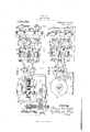
- Figure 1 is a plan view of my improved machine
- Fig. 2 is a section on the line 2-2, Fig. 1
- Fig. 3 is an end view
- Fig. 4' is a longitudinal section of the w'abbler and the cross-head'
- Fig. 5 isasection on the line 55 Fig. a j i
- the numeral 2 designates a suitable bedplate in which the driving mechanism is mounted.
- a motor 3 has the pinion 4 on its armature shaft meshing with the gear-wheel 5 on the stub-shaft6 mounted in suitable bearings
- a suitablezclutch 8, keyed on theshaft 8, is operated bythe lever 9 for moving said clutch into and out of engagement with the stub-shaft .6.
- the counter-shaft 1 0 is driven by the worm 11, 'onlthe shaft 8?, meshingwiththe w0r1n-wheell2 mounted on said shaft 10.
- the shaft 10 is mounted in suitable bearings13..-
- cam-disks 14 Mounted on the shaft 10is the cam-disks 14 with cams 15 formed on its periphery.
- the cams l5 gradually increase in size, reaching a maximum at 16 to provide for the gradually increased movementa-of the swaging dies, as more. fully hereinafter set forth.
- the periphery of the cam-disk 14 engages the idle roller 17 mounted on the rocker-arm 18 which is pivoted at 19 to the support 20.
- This rocker-arm18 has the seat 21 to receive the wabbler 22.
- This wabbler 22 fits in the recess 23 formed in the end of the plunger portion 24 of the cross-head 25.
- Ths cross-head 25 is of the spider form having four arms, which arms pass through openings 26 formed in the guide-frame 27.
- the guide-frame 27 has the flange 28, the bolts 29 passing through said flange are connected to the bearings 13.
- the opposite end of said guideframe 27 is connected by the bolts 30 to the stationary frame 31. In this manner, the guide-frame 27 is securely held in place and acts asa guide for the cross-head 25 and the plunger portion 24.
- the cross-head 25 is connected up by bolts 32 to the togglering 33.
- the springs 34 Mounted on the bolts 32 and interposed between the cross-head 25 and the stationary frame 31 are the springs 34.
- the guide-rods 35 connect the stationary frame 31 with the stationary-frame 36 and said guide-rods pass through openings in the toggle-ring 33, and form guides for said tog gle-ring' as it moves back and forth in the manner more fully hereinafter set forth.
- the toggle-ring 33 has the blocks 37 fitting in seats 38 and held in place by the bolts 39. Adjusting screws 40 are provided for adjusting the position of the blocks 37. These blocks 37 are arranged radially around the toggle-ring 33, and toggles 41 fit into seats 42 in said blocks 37, and the other ends of said toggle engage seats 43 in the swaging-jaws44. V
- Springs 49 on the bolts 50 are interposed between thenuts 51 on said bolts and the brackets 46, the inner ends of said bolts being secured into the 'swagingijaws 44. These springs act to return the jaws to normal position after they havebeen advanced in the swaging operation.
- Suitable swaging-dies 52 are bolted or otherwise secured to the swaging-jaws 44, said swaging-dies varying in shape accord ing to the shape to be given to the article to be swaged.
- Rotary movement is imparted to the cam disk 14 by throwing the clutch 8 into driving engagement with the power-shaft, and
Landscapes
- Engineering & Computer Science (AREA)
- Mechanical Engineering (AREA)
- Forging (AREA)
Description
R. W. RUTH.
SWAGING MACHINE.
APPLICATION FILED 1AN.I7,1918.
Patented June 10, 1919.
2 SHEETSSHEET l- INVENTO .ns NoRNls Psrsns co..1-momu1no., lmsumcrom u c.
R. W. RUTH.
SWAGING MACHINE.
APFL'ICAHON HLED JAN. 17.1918,
9 1 Wm 1T Em m up. T MW m2 6 M D1 INVEN R UMTED .SIA a TrA N OFFICE 1 Rd T m i og- E V ON, PENNSYLVANIA r swAenve- AcHInE.
To all whom it may concern f Be it knownthat I, ROBERT (W. RUTH, a
citizen of the United States, and resident of Belle Vernon, in the county of Fayette,
and Stateof Pennsylvania, have invented a new and useful Improvement in Swaging- Machines, and I do hereby declare the followin to be a full clear'and exact descri .2: a V 7 T eating dies, whose operation is attended with a great noise and severe yjarring action, which is not only nerve-racking to those 1n the vlcinity of such a machine, but is very severe on the wear and teardue to this jolti-ng and jarring action of-theparts. V t
In the accompanying drawings,Figure 1 is a plan view of my improved machine; Fig. 2 is a section on the line 2-2, Fig. 1; Fig. 3 is an end view; Fig. 4' is a longitudinal section of the w'abbler and the cross-head'; and Fig. 5 isasection on the line 55 Fig. a j i In the drawings, the numeral 2 designates a suitable bedplate in which the driving mechanism is mounted. A motor 3 has the pinion 4 on its armature shaft meshing with the gear-wheel 5 on the stub-shaft6 mounted in suitable bearings A suitablezclutch 8, keyed on theshaft 8, is operated bythe lever 9 for moving said clutch into and out of engagement with the stub-shaft .6.
The counter-shaft 1 0 is driven by the worm 11, 'onlthe shaft 8?, meshingwiththe w0r1n-wheell2 mounted on said shaft 10. The shaft 10 is mounted in suitable bearings13..-
Mounted on the shaft 10is the cam-disks 14 with cams 15 formed on its periphery. The cams l5 gradually increase in size, reaching a maximum at 16 to provide for the gradually increased movementa-of the swaging dies, as more. fully hereinafter set forth.
The periphery of the cam-disk 14 engages the idle roller 17 mounted on the rocker-arm 18 which is pivoted at 19 to the support 20. This rocker-arm18 has the seat 21 to receive the wabbler 22.
If Speeiiication of mar. Patent. 1
Patented June 10, 1919.
Application filed January 17, 19 18. Serial No. 212,183.
This wabbler 22 fits in the recess 23 formed in the end of the plunger portion 24 of the cross-head 25. Ths cross-head 25 is of the spider form having four arms, which arms pass through openings 26 formed in the guide-frame 27. The guide-frame 27 has the flange 28, the bolts 29 passing through said flange are connected to the bearings 13. The opposite end of said guideframe 27 is connected by the bolts 30 to the stationary frame 31. In this manner, the guide-frame 27 is securely held in place and acts asa guide for the cross-head 25 and the plunger portion 24.
l The cross-head 25 is connected up by bolts 32 to the togglering 33.
Mounted on the bolts 32 and interposed between the cross-head 25 and the stationary frame 31 are the springs 34.
The guide-rods 35 connect the stationary frame 31 with the stationary-frame 36 and said guide-rods pass through openings in the toggle-ring 33, and form guides for said tog gle-ring' as it moves back and forth in the manner more fully hereinafter set forth.
The toggle-ring 33 has the blocks 37 fitting in seats 38 and held in place by the bolts 39. Adjusting screws 40 are provided for adjusting the position of the blocks 37. These blocks 37 are arranged radially around the toggle-ring 33, and toggles 41 fit into seats 42 in said blocks 37, and the other ends of said toggle engage seats 43 in the swaging-jaws44. V
These jaws 44 are pivoted at their inner ends by the pins 45 to the brackets 46 secured to the stationary frame 31 by bolts 47. Adj usting screws 48 are provided for adjusting the position of the brackets 46.
Springs 49 on the bolts 50 are interposed between thenuts 51 on said bolts and the brackets 46, the inner ends of said bolts being secured into the 'swagingijaws 44. These springs act to return the jaws to normal position after they havebeen advanced in the swaging operation.
Suitable swaging-dies 52 are bolted or otherwise secured to the swaging-jaws 44, said swaging-dies varying in shape accord ing to the shape to be given to the article to be swaged.
The operation of my improved swaging machine is as follows:
Rotary movement is imparted to the cam disk 14 by throwing the clutch 8 into driving engagement with the power-shaft, and
as said cam-disk rotates, the cams 15 engage in succession the roller 17 and through the rocker-arm 18 impart a longitudinal movement to the cross-head 25 and likewise to the toggle-ring 33 connected thereto. The Y article to be swaged, having been properly heated,and let it be supposed that in this case the article consists of a short tubular section which is to be swaged by the dies 52,i-is inserted between the dies, andas the toggle-ring 33 is advanced by the; movement of thecross-head 25, the toggles d1 acting on the swaging-jaws 44 will move said aws inwardly and the swaging dies will be forced against the articleheld in position therein. As stated above, the cams 15. of the camdisk 14 gradually increasein size so that the inward movement of the swaging-jaws is slightly greater each time said toggle-ring advances, and the swaging action takes place gradually by a squeezing or apressing action until-the maximum cam 16 engages the roller 17 and the greatest movement is imparted to the swaging-rjaws whenthe swaging action is completed. 7 T o 'By this means for causing successively progressive radial movement to the dies, the swaging is accomplished by a gradual squeezing or pressing action, and the swa ing takes place without the awful din and clatter which is present in the swaging inachines ordinarily' employed where-there is a quick reciprocating action of the swagingdies and furthermore, by my improved ma-. chine, wear and tear on the parts is reduced to a minimumdue to the fact that there is none of the chattering or racking action such as is present in machines of thejrecip rocating type.
It will be apparent that the adjustments may be quickly made for taking care of. different sized articles to be swvaged for the amount of swaging to be donejto any article, and that the dies may be readily changed to impart diiferent sizes, shapes ortapers to the articles tobe swaged.
What I claim is: i
1. In a swaging-machine, the combination,
of radially-arranged movable swaging-dies,
and means for causing successively-progres co ies of h atent ay e o tained t fiv cen ae t'hva dr ssitathe fiommi i jonsrnof.Ifatents,
progressive radial movement is imparted to said dies.
4, In a swaging-maohlne, the comb nat on of radially-arranged movable swagin -dies,
a spring-actuated,togglea'ing, toggles interposed between said ring and said dies, and means for moving said toggle ring whereby succe ively progressive radial "movem nt i imparted tosaid .dics. a
.5. Ina swag'ing machine, the combination of radia ly-arrangedmovable swaging i a toggleing, toggles. interposed b e said ring and said dies, a cross-head conc t d to said ogglewring and means for moving said cross-head whereby successively progressive, radial movemen is impart d to saidd c r d In swagingzmachinajthe combinati n f rad a y arra ged movable swaging dic a toggle-1 in, toggles interposed betwee aid ri g an said dies, arotary cam+disk having cams,progressively:increasing in size, and connections from saidcam to said togglcaki g whereby successively progrcss adi -movement is imparted to Saidfdies,
7, In aswagingamachinathe combination of radially-arranged movable ,swagi-ng-t-jdies, a toggle ring, toggles. interposed between aid r ng andlsaid dies, atcrossheadiconnected to said toggle-ring, alcamedisk having graduallyrincreasing cams, connections between saidcamrring'yand said cross-head, whereby successively progressive radial movement is imparted toisaid dies. a 8- In a singing-machine.the combination with radiallyEarr-anged movable swag-ingdies, togglerri-ng, toggles interposed beween said'ring and said dies, crossrhead connectedto said toggleeringta plung'erportion on said crossrheadihavingia seat therein, a :wabbler-engaging. said seat, a rocker? arm engag ng said .wabbler a-nd a cam-disk having cams progressively increasing in radius.engagingsaidrockemanm;.
9. In a-iswvagingsmachine, the combination of-"radially-farranged, pivotallye'monnted, springractnated swagingr-dies, and meansfor causing successively progressive radial moves ment'tolsaid dies. Y
In testimony whereof I the said ROBERT W. .RU.TH, have-hereunto setmy hand;
' notes W. RUT
lVit'nesses; j .Ronm'DrTorrnn,
JOHN- Was in t I -f G3 r V
Publications (1)
| Publication Number | Publication Date |
|---|---|
| US1306232A true US1306232A (en) | 1919-06-10 |
Family
ID=3373759
Family Applications (1)
| Application Number | Title | Priority Date | Filing Date |
|---|---|---|---|
| US1306232D Expired - Lifetime US1306232A (en) | Swaging machine |
Country Status (1)
| Country | Link |
|---|---|
| US (1) | US1306232A (en) |
Cited By (2)
| Publication number | Priority date | Publication date | Assignee | Title |
|---|---|---|---|---|
| US3084571A (en) * | 1960-06-20 | 1963-04-09 | Appel Process Ltd | Forging machines |
| US4644777A (en) * | 1984-09-07 | 1987-02-24 | Siegmund Kumeth | Device for grooving cylindrical workpieces |
-
0
- US US1306232D patent/US1306232A/en not_active Expired - Lifetime
Cited By (2)
| Publication number | Priority date | Publication date | Assignee | Title |
|---|---|---|---|---|
| US3084571A (en) * | 1960-06-20 | 1963-04-09 | Appel Process Ltd | Forging machines |
| US4644777A (en) * | 1984-09-07 | 1987-02-24 | Siegmund Kumeth | Device for grooving cylindrical workpieces |
Similar Documents
| Publication | Publication Date | Title |
|---|---|---|
| US1306232A (en) | Swaging machine | |
| US130371A (en) | Improvement in mechanical movements for converting motion | |
| US582283A (en) | grimes | |
| US336656A (en) | Machine for radial crimping | |
| US875746A (en) | Machine for making radiators. | |
| US330670A (en) | billinqs | |
| US364119A (en) | Machine for making wire nails | |
| US336304A (en) | ellis | |
| US317689A (en) | Machine for rounding the backs of books | |
| US722300A (en) | Machine for finishing the ends of blanks. | |
| US685477A (en) | Spike-making machine. | |
| US578401A (en) | Carl grtjber | |
| US142250A (en) | Improvement in machines for forming the backs of saws | |
| US646021A (en) | Stovepipe-elbow-making machine. | |
| US835065A (en) | Automatic cutting, forming, and assembling machine. | |
| US576271A (en) | Brick-machine | |
| US818807A (en) | Drawing-press. | |
| US1322861A (en) | Drawing-press | |
| US748870A (en) | Machine for rolling carpenters squares | |
| US755435A (en) | Sheet-folding machine. | |
| US1153199A (en) | Hay-press. | |
| US1543891A (en) | Mechanical movement and engine | |
| US353529A (en) | Needle-swaging machine | |
| US1457785A (en) | Valve grinder | |
| US24174A (en) | Machine for making clay pipes |