US1298256A - Internal-combustion engine. - Google Patents
Internal-combustion engine. Download PDFInfo
- Publication number
- US1298256A US1298256A US24843418A US24843418A US1298256A US 1298256 A US1298256 A US 1298256A US 24843418 A US24843418 A US 24843418A US 24843418 A US24843418 A US 24843418A US 1298256 A US1298256 A US 1298256A
- Authority
- US
- United States
- Prior art keywords
- power
- cylinder
- charging
- cylinders
- mixture
- Prior art date
- Legal status (The legal status is an assumption and is not a legal conclusion. Google has not performed a legal analysis and makes no representation as to the accuracy of the status listed.)
- Expired - Lifetime
Links
Images


Classifications
-
- F—MECHANICAL ENGINEERING; LIGHTING; HEATING; WEAPONS; BLASTING
- F02—COMBUSTION ENGINES; HOT-GAS OR COMBUSTION-PRODUCT ENGINE PLANTS
- F02B—INTERNAL-COMBUSTION PISTON ENGINES; COMBUSTION ENGINES IN GENERAL
- F02B25/00—Engines characterised by using fresh charge for scavenging cylinders
Definitions
- This invention relates to internal combustion engines, the broad object of the invention being to produce a practical and reliable engine of the class referred to in which there is an explosion or impulse in each cylinder each revolution of the crank shaft.
- the engine operates on the two-cycle principle, I eliminate crank case compression and" the resist- 7 ance or burden thrown upon the engine by reason of such crank case compression, there by enabling the engine to deliver greater horse power in proportion to the bore stroke of the cylinders and pistons.
- a further object of the invention is to provide novel means for charging the cylinders with explosive mixture in such a way that the cylinders will not require valves and valve mechanism of any kind, thereby elimihating the. cam shaft and all valve mechanism, the -mixture entering each cylinder freely and uncontrolled by the valves, and the burned gases leaving the cylinders through ports which are covered and uncovered by the pistons.
- Another object of the invention is to produce an en ine which will operate with high power efliclency under hydro-carbon oils of a lower grade than gasolene, the mixture being heated to a high degree before it is conducted into the combustion chambers. This results in fuel economy, a more highly combustible mixture, greater power, and greater freedom from carbon deposits.
- Another object of the invention is to provide means for compressing and storing air
- said compressed air being utilized in conjunction with the water cooling system to promote a rapid circulation of the water and also to cool the water by reason of the cooled air mixing directly there-- with, such compressed air being also used for pumping tires, maintaining the necessary pressure in the fuel tank and for any other purpose.
- Figure 1 is a side elevation of the engine looking toward the intake side thereof.
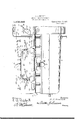
- Fig. 2 is a vertical longitudinal section through the engine.
- Fig. 3 is a vertical transverse section through one of the power cylinders.
- Fig. 4 is a vertical transverse section through one of the pumping cylinders on' the line 4-4 of Fig. 2.
- Fig. 5 is an enlarged fragmentary vertical sectional view of the mixture inlet valve mechanism.
- the engine contemplated in this invention comprises a plurality of power cylinders 1 and a plurality of pumping cylinders 2 which are preferably arranged in relation to each other, as shown in Fig. 2, each of the pumping cylinders 2 being arranged between two power cylinders 1.
- a plurality of power cylinders 1 and a plurality of pumping cylinders 2 which are preferably arranged in relation to each other, as shown in Fig. 2, each of the pumping cylinders 2 being arranged between two power cylinders 1.
- I have shown four power cylinders 1 and two pumping cylinders2, each pumping cylinder being adapted to charge the two power cylinders located adjacent thereto and on opposite sides,,thereof.
- the power pistons 3 are connected to the crank shaft 4 by the usual connecting rods 5, 6 designating a fly wheel on one end of the crank shaft.
- 7 represents the crank case which is adapted to contain oil, said crank case having pockets 8 in which the cranks dip in order to provide for what is known as splash lubrication.
- the lubricating system is also shown as comprising an oil supply pipe 9. having branches 10 leading to the main crank shaft bearings 11.
- a water jacket. 12 having a water inlet 13 and a water outlet 14. Said jacket is also provided with an air inlet 15 at one end thereof. the air pumped into said jacket under pressure. as will hereinafter appear. mixing directly with and serving to cool the water and also accelerate the circulation of the water by driving the water along with it; said air passing with the water out through the outlet H and to the radiator, (not shown), where the water and air are again separated. as will readily be understood by those familiar with the art to which this invention appertains.
- the mixture drawn from the carburetor 16 is carried through an intake manifold 17 to a plurality of valve chambers 18 and after leaving the chambers 18, the mixture is conducted through pipes 19 into the power cylinders 1, each of which has an internally arranged nozzle 20 as shown in Figs. 2 and 3, each nozzle discharging centrally of the combustion chamber and just under the center of the head of thecylinder through which is inserted a spark plug 21.
- the burned gases in the cylinders 1 pass outwardly through oppositely arranged exhaust ports 22 into exhaust manifolds 23 extending along opposite sides of the engine and thence to the muflier or atmosphere. It will thus be seen that the power cylinders are free from intake valves and exhaust and therefore there is no need for a valve operating cam shaft.
- each casing 18 passes by one or the other of a pair of normally closed check valves 24 as best shown in Fig. ing the casing 18 passes by one of a pair of normally closed check valves 25, control-ling the receiving end of the respective pipes 19, hereinabove referred to.
- the casing 18 is divided by a central partition 26 into tWo separatecompartments or chambers 27. and 28 as shown in Fig. 5, and each compartment communicates with the adjacent pumping or charging cylinder 2 by means of a port 29, one of which is shown in Fig. l.
- each pumping cylinder 2 there is arranged a central partition 30 through which reciprocates a piston rod 31 having fast thereon two pistons 32 and 33, one operating above the partition 30 and the other operating below said partition.
- a piston rod 31 having fast thereon two pistons 32 and 33, one operating above the partition 30 and the other operating below said partition.
- mixture is drawn in the chamber above the partition 30 and in the return or downward stroke of said piston 32. the mixture is forced from said chamber and from the charging piston into the combustion chamber of one of the adjacent power cylinders.
- a charge is drawn into the chamber below the partition 30 and in the .return or upward stroke of the piston 33.
- cranks 34 which control the strokes of the pumping pistons are ofl'set ninety degrees from the cranks of theadjacent power pistons.
- thecompressing piston isshown at the upper limit of its movement.
- the piston rod 31 is'of tubular formation, open at its lower end next to the crank case and having the opposite end thereof controlled by a small check valve Oil may thus reach the upper face of the upper piston 32.
- the space above the piston 32 forms an air compressing chamber 36 which is pierced by "an air port 37 through which the air enters'and leaves the chamber 36, the air being drawn into said chamber during the down stroke of the piston 32 and being forced through said port 37 during the up stroke of said piston.
- 38 designates an air intake manifold having two remotely located air inlets 39. (see Fig. 1). In .each branch of the manifold there is.
- a check valve 40 beyond which is an elbow 41 which communicates directly with the air inlet and ,outlet port 37 of the respective pot nping or charging cylinder.
- the manifold 38 is provided with another check valve 42 for each branch. From the manifold a compressed air pipe 43 leads to a storage tank 4+1 shown as arranged at. one end of the engine.
- the storf 45 to the air inlet' opening 15 of the water jacket as hereinabove described. cold air being thus forced under pressure into the circulating water of the cooling system, re' ducing the temperature of the water accelcrating the movement or circulation thereof as hereinabove noted.
- a pipe 45 is controlled by a feed regulating valve 46 so that more or less air may be forced into the circulating water according to the season of the year and other conditions. Oil reaching the tank44 from the chambers 36 of the charging cylinders may be drained into the crank case whenever necessary by means of a pipe 47 containing a stop cock 4-8.
- the tank 44 is connected with the exhaust manifold 23 by means of a pipe 49 which is controlled adjacent to the tank 44 by a low pressure valve 50 which automatically opens and relieves the pressure when it reaches a predetermined degree in the tank 44.
- said tank 44 is also equipped with a high pressure relief valve 51 and is also provided with a service nipple or connection 52 controlled by a stop cock 53.
- a stop cook 54 is arranged in the pipe 49 between the low pressure valve 50 and the high pressure valve 51. Under ordinary working conditions, the stop cock 54 is left open so that. air under a predetermined pressure passes through the pipe 45 into the water jacket of the engine.
- valve 50 In case there is an excess pressure, the valve 50 automatically opens and releases such excess pressure.
- the stop cock 54 When it is desired to inflate a tire or raise the pressure in the fuel tank, the stop cock 54 is closed, which thereby cuts out the valve 50. Then the air pressure in the tank 44 may be raised to the limit allowed by the high pressure valve 51. The compressed air is then delivered through the nipple 52 and a suitable pipe or hose applied thereto to the service point.
- the explosive mixture drawn from the earbureter 16 passes into the valve chambers 18. It is then drawn into one of the pumping and charging cylinders and is forced therefrom into the casing or chamber 18 between the check valves 24 and 25. The mixture is then blown past the check valves 25 serving to cool and clean the same. The mixture then passes through the heated pipes 19 which are m free communication with the combustion chambers, and are constantly heated by the explosives, a portion of the expanding mixture flowing through the pipes 19 but being checked by the valves 25. Therefore, the explosive mixture is raised to a comparatively high temperature before it reaches the combustion chambers.
- the cam shaft is eliminated and also the usual intake and exhaust valves with which the cylinders of internal combustion engines are ordinarily equipped for the purpose of controlling the supply of mixture to each cylinder and the exhaust of the burned gases therefrom.
- the engine may be operated with gasolene or a lower grade fuel 011, such as kerosene on account of the heating of the mixture before it reaches the combustion chambers.
- a multiple cylinder internal combustion engine the combination of a pair of power cylinders, a charging cylinder arranged between .and adjacent to said power cylinders, a crank shaft to which the power pistons are connected at approximately one hundred and eighty degrees offset, a double charging piston operatively connected to said crank shaft at a ninety degree offset from the power pistons, and a partition in the charging cylinder, the charging piston having two heads working at opposite sides of said partition, said charging piston operating in one stroke to draw in a charge of explosive mixture and at the same time expel another charge into one power cylinder and in the return stroke to draw in another charge of explosive mixture and at the same time expel a charge into the other power cylinder. and a compressed air tank in communication with one end of the charging cylinder beyond said char ing piston.
- a multiple cylinder internal combustion engine the combination of a pair of power cylinders. a charging cylinder arranged between and adjacent to said power cylinders, a crank shaft to which the power pistons are. connected at approximately one hundred and eighty degrees offset. a double charging piston operatively connected to said crank shaft at a ninety degree offset from the power pistons. a partition in the charging cylinder. the charging piston having two heads working at opposite sides of said partition, said charging piston operating in one stroke to draw in a charge of explosive mixture and at the same time expel another charge into one power cylinder and in the return stroke to draw in another charge of explosive mixture and at the same.
- a crank shaft to which the power pistons are connected at approximately one hundred and eighty degrees offset
- a double charging piston operatively connected to said crankshaft at a ninety degree offset from the power pistons
- a partition in the charging cylinder the charging piston having two heads working at opposite sides of saidpartltion, said charging piston operatvi ing in one stroke to draw in a charge of explosive mixture and at the same time expel another charge into one power cyllnder and in the return stroke to draw 1n another charge of explosive mixture and at the same time expel a charge into the other power cylinder, a mixture supply, a valve chamber located between said supply and the charging cylinder, inlet valves controlling communication between said supply and said valve chamber, pipes leading from said valve chamber to said. power cylinders, and check Valves controlling the receiving ends of the last named pipes.
- a multiple cylinder internal combustion engine the combination of a pair of power cylinders, a charging cylinder arranged between and adjacent to said power cylinders, a crank shaft to which the power pistons are connected at approximately one hundred'.and eighty degreesoffset, a double charging piston operatively connected to said crank shaft at a ninety degree offset from the power pistons, a partition in the charging cylinder, the charging piston having two heads working at opposite sides of said partition, said charging piston operating in one stroke to draw in'a charge of explosive mixture and at the same time expel another charge into one power cylinder and in the return stroke to draw in another charge of explosive mixture and at the same time expel a charge into the other power cylinder, a mixture supply, a valve chamber located between said supply and the charging cylinder, inlet valves controlling communication between said supply and said valve chamber, pipes leading from said valve chamber to saidpower cylinders, and check valves controlling the receiving ends of the last named pipes, the latter being in freely opencommunication with the combustion chambers of the respective power cylinders.
- a multiple cylinder internal combustion engine the combination of a pair of power cylinders, a charging cylinder arranged between and adjacent to said power cylinders, a crank shaft to which the power pistons are connected at approximately one hundred and eighty degrees offset, a double charging piston operatively connected to said crank shaft at a ninety degree offset from the power pistons, a partition in the charging cylinder, the charging piston having two heads working at opposite sides of said partition.
- said charging piston operating in one stroke to draw in a charge of explosive mixture and at the same time expel another charge into one power cylinder and in the return stroke to draw in another charge of explosive mixture and at the same time expel a charge into the other power cylinder, a mixture supply.
- a valve chamber located between said supply and the charging cylinder. inlet valves controlling communication between said supply and said valve chamber, pipes leading from said.
- valve chamber to said power cylinders, and check valvescontrolling the receiving ends of the last named pipes, the latter being provided at their discharge end with nozzles'located within the combustion chambers of the power cylinders and terminating centrally of the combustion spaces and in juxtaposition to the ignition elements.
- a multiple cylinder internal cornbastion engine the combination of a pair of power cylinders, a charging cylinder ar' ranged betweenand adjacent to said power cylinders, a crank shaft to which the power pistons are connected at approxin'iately one hundred and eighty degrees offset, a double charging piston operatively connected to said crank shaft-at a ninety degree offset from the power pistons, a partition in the charging cylinder, the charging piston having twoheads working at opposite sides of said partition, said charging piston operating in one stroke to draw in a charge of explosive mixture and at the same time expel another charge into one power cylinder and in the return stroke to draw in another charge of explosive mixture and at the same time expel a charge into the other power cylinder, an air inlet pipe communicating with the space in the head portion of the charging cylinder and having check valves at opposite sides of such point of communication, and a compressed air tank into which said pipe discharges.
- a multiple cylinder internal combustion engine the combination of a pair of power cylinders, a charging cylinder arranged between and adjacent .to said power cylinders, a crank shaft to which the power pistons are connected at approximately one hundred and eighty degrees offset, a double charging piston operatively connected to said crank shaft at a ninety degree offset from the power pistons, a' partition in the charging cylinder, the charging piston having two heads working at opposite sides of said partition, said charging piston operatin; in one stroke to draw in a charge of explosive mixture and at the same time expel another charge into one power cylinder and in the return stroke to draw in another 5charge of explosive mixture and at the same lion engine, the combination of a pair ofpower cylinders, a chargmg cylinder arranged between and adjacent to said power cylinders.
- a crank shaft to which the power pistons are connected at approximatelyone hundred and eighty degrees offset
- a double charging piston operatively connected to said crank shaft at a ninety degree offset from the power pistons
- a partition in the charging cylinder the charging piston having two heads working at opposite sides of said partition, said charging piston operating in one stroke to draw in a charge of explosivemixture and at the same time expel another charge into one power cylinder and in the return stroke to draw in another charge of explosive mixture and at the same time expel a charge into the other power cylinder, a pipe leading from the chamber in the head portion of the compressing cylinder, a compressed an tank into which said pipe discharges. a pipe leading from said tank to the water jacket of the engine, an air feed regulating valve controlling the last named pipe, and a pressure relief valve for said tank.
Landscapes
- Engineering & Computer Science (AREA)
- Chemical & Material Sciences (AREA)
- Combustion & Propulsion (AREA)
- Mechanical Engineering (AREA)
- General Engineering & Computer Science (AREA)
- Cylinder Crankcases Of Internal Combustion Engines (AREA)
Description
A. A. PROFFITT.
INTERNAL COMBUSTION ENGINE.
APPLICATION FILED AUG.5. I918.
1,298,256 Patented Mar. 25, 1919.
4 SHEETS-SHEET 3812 1 awvewlroz' A. A. PROFFITT.
INTERNAL COMBUSTION ENGINE.
APPLICATION FILED AUG.5. 1918.
1,298,256. Patented M111. 1919.
4 SHEETS-SHEET 2.
witnesses I gnaw/14. 60:
E. Q. JTJiProffvLtt W%% 3% y 5% W A. A. PROFFITT.
INTERNAL COMBUSTION ENGINE.
APPLICATION FILED AUG.5, I918.
1,298,256. Patented Mar. 25, 1919 4 SHEETS-SHEET 3.
929' t Q 5 t 51 fi '15. J17. Profftfi A. A. PROFFITT.
INTERNAL COMBUSTION ENGINE;
APPLICATION FILED AuG.5. 191's.
1,298,256. Patented Mar. 25, 1919.
4 SHEETS-SHEET 4.
witnesses amen/to:
a. Q. wk. 274 m 9 W for ARBA A. PROFFITT, OF GIBSON CITY, ILLINOIS.
INTERNAL-COMBUSTION ENGINE.
Specification of Letters Patent.
Patented Mar. 25, 1919.
Application filed August 5. 1918.-.. Serial No. 248,434.
To all whom it may concern:
Be it known that I. :\RB.\ A. PROFFITT, a citizen of the United States, residing at Gibson City, in the county of Ford and State of Illinois, have invented new and useful Improvements in Internal-Combustion Eli-- gines, of which the following is a specification.
This invention relates to internal combustion engines, the broad object of the invention being to produce a practical and reliable engine of the class referred to in which there is an explosion or impulse in each cylinder each revolution of the crank shaft. lVhile in the respect just noted, the engine operates on the two-cycle principle, I eliminate crank case compression and" the resist- 7 ance or burden thrown upon the engine by reason of such crank case compression, there by enabling the engine to deliver greater horse power in proportion to the bore stroke of the cylinders and pistons.
A further object of the invention is to provide novel means for charging the cylinders with explosive mixture in such a way that the cylinders will not require valves and valve mechanism of any kind, thereby elimihating the. cam shaft and all valve mechanism, the -mixture entering each cylinder freely and uncontrolled by the valves, and the burned gases leaving the cylinders through ports which are covered and uncovered by the pistons.
Another object of the invention is to produce an en ine which will operate with high power efliclency under hydro-carbon oils of a lower grade than gasolene, the mixture being heated to a high degree before it is conducted into the combustion chambers. This results in fuel economy, a more highly combustible mixture, greater power, and greater freedom from carbon deposits.
Another object of the invention is to provide means for compressing and storing air,
concurrently with the charging of the cylinders with their respective supplies of explosive mixture, said compressed air being utilized in conjunction with the water cooling system to promote a rapid circulation of the water and also to cool the water by reason of the cooled air mixing directly there-- with, such compressed air being also used for pumping tires, maintaining the necessary pressure in the fuel tank and for any other purpose.
With the above and other objects in view,
the invention consists in the construction, combination and arrangement of parts, as herein described, illustrated and claimed.
In the accompanying drawings Figure 1 is a side elevation of the engine looking toward the intake side thereof.
Fig. 2 is a vertical longitudinal section through the engine.
Fig. 3 is a vertical transverse section through one of the power cylinders.
Fig. 4 is a vertical transverse section through one of the pumping cylinders on' the line 4-4 of Fig. 2.
Fig. 5 is an enlarged fragmentary vertical sectional view of the mixture inlet valve mechanism.
The engine contemplated in this invention comprises a plurality of power cylinders 1 and a plurality of pumping cylinders 2 which are preferably arranged in relation to each other, as shown in Fig. 2, each of the pumping cylinders 2 being arranged between two power cylinders 1. For convenience I have shown four power cylinders 1 and two pumping cylinders2, each pumping cylinder being adapted to charge the two power cylinders located adjacent thereto and on opposite sides,,thereof.
The power pistons 3 are connected to the crank shaft 4 by the usual connecting rods 5, 6 designating a fly wheel on one end of the crank shaft. 7 represents the crank case which is adapted to contain oil, said crank case having pockets 8 in which the cranks dip in order to provide for what is known as splash lubrication. The lubricating system is also shown as comprising an oil supply pipe 9. having branches 10 leading to the main crank shaft bearings 11.
Extending around all of the cylinders 1 and 2 is a water jacket. 12 having a water inlet 13 and a water outlet 14. Said jacket is also provided with an air inlet 15 at one end thereof. the air pumped into said jacket under pressure. as will hereinafter appear. mixing directly with and serving to cool the water and also accelerate the circulation of the water by driving the water along with it; said air passing with the water out through the outlet H and to the radiator, (not shown), where the water and air are again separated. as will readily be understood by those familiar with the art to which this invention appertains.
Referring now to Fig. 1. the mixture drawn from the carburetor 16 is carried through an intake manifold 17 to a plurality of valve chambers 18 and after leaving the chambers 18, the mixture is conducted through pipes 19 into the power cylinders 1, each of which has an internally arranged nozzle 20 as shown in Figs. 2 and 3, each nozzle discharging centrally of the combustion chamber and just under the center of the head of thecylinder through which is inserted a spark plug 21. The burned gases in the cylinders 1 pass outwardly through oppositely arranged exhaust ports 22 into exhaust manifolds 23 extending along opposite sides of the engine and thence to the muflier or atmosphere. It will thus be seen that the power cylinders are free from intake valves and exhaust and therefore there is no need for a valve operating cam shaft.
The explosive mixture enters each casing 18 at the bottom, passing by one or the other of a pair of normally closed check valves 24 as best shown in Fig. ing the casing 18 passes by one of a pair of normally closed check valves 25, control-ling the receiving end of the respective pipes 19, hereinabove referred to. The casing 18 is divided by a central partition 26 into tWo separatecompartments or chambers 27. and 28 as shown in Fig. 5, and each compartment communicates with the adjacent pumping or charging cylinder 2 by means of a port 29, one of which is shown in Fig. l. In each pumping cylinder 2 there is arranged a central partition 30 through which reciprocates a piston rod 31 having fast thereon two pistons 32 and 33, one operating above the partition 30 and the other operating below said partition. In the upward stroke of the piston 3:2, mixture is drawn in the chamber above the partition 30 and in the return or downward stroke of said piston 32. the mixture is forced from said chamber and from the charging piston into the combustion chamber of one of the adjacent power cylinders. I Likewise, in the downward stroke of thepiston 33 a charge is drawn into the chamber below the partition 30 and in the .return or upward stroke of the piston 33.
such charge is forced into the combustion chamber of the other adjacent power cylinder. It will thus be understood that the mixture drawn through the intake manifold into the valve casing 18 is first drawn into the charging cylinder 2 and then forced back into the casing 18 and from there the mixture passes one of the check valves 25 and continues through one of the pipes 19 to the respective combustion chamber.
By reference to Fig. 2, it will be noted that the cranks 34 which control the strokes of the pumping pistons are ofl'set ninety degrees from the cranks of theadjacent power pistons. Referring to the three right hand cylinders in Fig. 2', thecompressing piston isshown at the upper limit of its movement.
The mixture leavvwhile the power pistons at opposite sides thereof are shown one half way down on its 1 working stroke and the other half way up on its compressing stroke. lVhen the pis tons are in the position just referred to, one of the power cylinders has ust been charged with mixture received from the space below the partition 30 in the pumping cylinder 2, while the space above said partition 30 is filled with mixture drawn in by the upward movement of the upper piston 32. It will thus be seen that very little load or resistance is imposed on the pumping piston which merely reciprocates back and forth with an easy smooth movement, drawing in a charge of gas and then forcing the same with a light pressure into one of the power cylinders. The mixture is not compressed in the charging cylinder but is merely drawn into and forced out of the same.
In order to provide for an etlicient lubrication of the pumping pistons and cylinders, the piston rod 31 is'of tubular formation, open at its lower end next to the crank case and having the opposite end thereof controlled by a small check valve Oil may thus reach the upper face of the upper piston 32. The space above the piston 32 forms an air compressing chamber 36 which is pierced by "an air port 37 through which the air enters'and leaves the chamber 36, the air being drawn into said chamber during the down stroke of the piston 32 and being forced through said port 37 during the up stroke of said piston. 38 designates an air intake manifold having two remotely located air inlets 39. (see Fig. 1). In .each branch of the manifold there is. arranged a check valve 40 beyond which is an elbow 41 which communicates directly with the air inlet and ,outlet port 37 of the respective pui nping or charging cylinder. Beyond the opening 41, the manifold 38 is provided with another check valve 42 for each branch. From the manifold a compressed air pipe 43 leads to a storage tank 4+1 shown as arranged at. one end of the engine.
The storf 45 to the air inlet' opening 15 of the water jacket as hereinabove described. cold air being thus forced under pressure into the circulating water of the cooling system, re' ducing the temperature of the water accelcrating the movement or circulation thereof as hereinabove noted. A pipe 45 is controlled by a feed regulating valve 46 so that more or less air may be forced into the circulating water according to the season of the year and other conditions. Oil reaching the tank44 from the chambers 36 of the charging cylinders may be drained into the crank case whenever necessary by means of a pipe 47 containing a stop cock 4-8.
The tank 44 is connected with the exhaust manifold 23 by means of a pipe 49 which is controlled adjacent to the tank 44 by a low pressure valve 50 which automatically opens and relieves the pressure when it reaches a predetermined degree in the tank 44. In order to provide for utilizing the compressed air for pumping tires and raising the pressure in the fuel tank and for any other purpose, said tank 44 is also equipped with a high pressure relief valve 51 and is also provided with a service nipple or connection 52 controlled by a stop cock 53. A stop cook 54 is arranged in the pipe 49 between the low pressure valve 50 and the high pressure valve 51. Under ordinary working conditions, the stop cock 54 is left open so that. air under a predetermined pressure passes through the pipe 45 into the water jacket of the engine. In case there is an excess pressure, the valve 50 automatically opens and releases such excess pressure. When it is desired to inflate a tire or raise the pressure in the fuel tank, the stop cock 54 is closed, which thereby cuts out the valve 50. Then the air pressure in the tank 44 may be raised to the limit allowed by the high pressure valve 51. The compressed air is then delivered through the nipple 52 and a suitable pipe or hose applied thereto to the service point.
From the foregoing description, taken in connection with the accompanying drawings, the operation of the engine will now be understood. The explosive mixture drawn from the earbureter 16 passes into the valve chambers 18. It is then drawn into one of the pumping and charging cylinders and is forced therefrom into the casing or chamber 18 between the check valves 24 and 25. The mixture is then blown past the check valves 25 serving to cool and clean the same. The mixture then passes through the heated pipes 19 which are m free communication with the combustion chambers, and are constantly heated by the explosives, a portion of the expanding mixture flowing through the pipes 19 but being checked by the valves 25. Therefore, the explosive mixture is raised to a comparatively high temperature before it reaches the combustion chambers. This renders the mixture more combustible and it is ignited more easily for that reason. Very little load is imposed on the charging pistons as they merely draw in the mixture and expel the same into the combustion chamber, the result being that each power cylinder is given .a full and complete charge of fresh mixture which travels the full length of the combustion chamber, forcing out the burned gases through the ports 22. It will also be understood that there is an impulse in any cylinder for each revolution of the crank shaft and by reason of the arrangement of the cranks. in the engine illustrated in the drawings. and comprising four power cylinders, there is an impulse for each ninety degree movement of the crank shaft. Such overlapping of the impulses thus produces an engine having in effect a continuous torque. By reason of the construction described. the cam shaft is eliminated and also the usual intake and exhaust valves with which the cylinders of internal combustion engines are ordinarily equipped for the purpose of controlling the supply of mixture to each cylinder and the exhaust of the burned gases therefrom. The engine may be operated with gasolene or a lower grade fuel 011, such as kerosene on account of the heating of the mixture before it reaches the combustion chambers.
I do not desire to be restricted to the particular construction and arrangement herein shown and described, it being obvious that various changes in the form, proportion and minor details of construction, may be resorted to without departing from the principle or sacrificing any of the advantages of the invention.
1. In a multiple cylinder internal combustion engine, the combination of a pair of power cylinders, a charging cylinder arranged between .and adjacent to said power cylinders, a crank shaft to which the power pistons are connected at approximately one hundred and eighty degrees offset, a double charging piston operatively connected to said crank shaft at a ninety degree offset from the power pistons, and a partition in the charging cylinder, the charging piston having two heads working at opposite sides of said partition, said charging piston operating in one stroke to draw in a charge of explosive mixture and at the same time expel another charge into one power cylinder and in the return stroke to draw in another charge of explosive mixture and at the same time expel a charge into the other power cylinder. and a compressed air tank in communication with one end of the charging cylinder beyond said char ing piston.
2. n a multiple cylinder internal combustion engine, the combination of a pair of power cylinders. a charging cylinder arranged between and adjacent to said power cylinders, a crank shaft to which the power pistons are. connected at approximately one hundred and eighty degrees offset. a double charging piston operatively connected to said crank shaft at a ninety degree offset from the power pistons. a partition in the charging cylinder. the charging piston having two heads working at opposite sides of said partition, said charging piston operating in one stroke to draw in a charge of explosive mixture and at the same time expel another charge into one power cylinder and in the return stroke to draw in another charge of explosive mixture and at the same.
cylinders, a crank shaft to which the power pistons are connected at approximately one hundred and eighty degrees offset, a double charging piston operatively connected to said crankshaft at a ninety degree offset from the power pistons, a partition in the charging cylinder, the charging piston having two heads working at opposite sides of saidpartltion, said charging piston operatvi ing in one stroke to draw in a charge of explosive mixture and at the same time expel another charge into one power cyllnder and in the return stroke to draw 1n another charge of explosive mixture and at the same time expel a charge into the other power cylinder, a mixture supply, a valve chamber located between said supply and the charging cylinder, inlet valves controlling communication between said supply and said valve chamber, pipes leading from said valve chamber to said. power cylinders, and check Valves controlling the receiving ends of the last named pipes.
4. In a multiple cylinder internal combustion engine, the combination of a pair of power cylinders, a charging cylinder arranged between and adjacent to said power cylinders, a crank shaft to which the power pistons are connected at approximately one hundred'.and eighty degreesoffset, a double charging piston operatively connected to said crank shaft at a ninety degree offset from the power pistons, a partition in the charging cylinder, the charging piston having two heads working at opposite sides of said partition, said charging piston operating in one stroke to draw in'a charge of explosive mixture and at the same time expel another charge into one power cylinder and in the return stroke to draw in another charge of explosive mixture and at the same time expel a charge into the other power cylinder, a mixture supply, a valve chamber located between said supply and the charging cylinder, inlet valves controlling communication between said supply and said valve chamber, pipes leading from said valve chamber to saidpower cylinders, and check valves controlling the receiving ends of the last named pipes, the latter being in freely opencommunication with the combustion chambers of the respective power cylinders.
In a multiple cylinder internal combustion engine, the combination of a pair of power cylinders, a charging cylinder arranged between and adjacent to said power cylinders, a crank shaft to which the power pistons are connected at approximately one hundred and eighty degrees offset, a double charging piston operatively connected to said crank shaft at a ninety degree offset from the power pistons, a partition in the charging cylinder, the charging piston having two heads working at opposite sides of said partition. said charging piston operating in one stroke to draw in a charge of explosive mixture and at the same time expel another charge into one power cylinder and in the return stroke to draw in another charge of explosive mixture and at the same time expel a charge into the other power cylinder, a mixture supply. a valve chamber located between said supply and the charging cylinder. inlet valves controlling communication between said supply and said valve chamber, pipes leading from said.
valve chamber to said power cylinders, and check valvescontrolling the receiving ends of the last named pipes, the latter being provided at their discharge end with nozzles'located within the combustion chambers of the power cylinders and terminating centrally of the combustion spaces and in juxtaposition to the ignition elements.
6. In a multiple cylinder internal cornbastion engine, the combination of a pair of power cylinders, a charging cylinder ar' ranged betweenand adjacent to said power cylinders, a crank shaft to which the power pistons are connected at approxin'iately one hundred and eighty degrees offset, a double charging piston operatively connected to said crank shaft-at a ninety degree offset from the power pistons, a partition in the charging cylinder, the charging piston having twoheads working at opposite sides of said partition, said charging piston operating in one stroke to draw in a charge of explosive mixture and at the same time expel another charge into one power cylinder and in the return stroke to draw in another charge of explosive mixture and at the same time expel a charge into the other power cylinder, an air inlet pipe communicating with the space in the head portion of the charging cylinder and having check valves at opposite sides of such point of communication, and a compressed air tank into which said pipe discharges.
7. In a multiple cylinder internal combustion engine, the combination of a pair of power cylinders, a charging cylinder arranged between and adjacent .to said power cylinders, a crank shaft to which the power pistons are connected at approximately one hundred and eighty degrees offset, a double charging piston operatively connected to said crank shaft at a ninety degree offset from the power pistons, a' partition in the charging cylinder, the charging piston having two heads working at opposite sides of said partition, said charging piston operatin; in one stroke to draw in a charge of explosive mixture and at the same time expel another charge into one power cylinder and in the return stroke to draw in another 5charge of explosive mixture and at the same lion engine, the combination of a pair ofpower cylinders, a chargmg cylinder arranged between and adjacent to said power cylinders. a crank shaft to which the power pistons are connected at approximatelyone hundred and eighty degrees offset, a double charging piston operatively connected to said crank shaft at a ninety degree offset from the power pistons, a partition in the charging cylinder, the charging piston having two heads working at opposite sides of said partition, said charging piston operating in one stroke to draw in a charge of explosivemixture and at the same time expel another charge into one power cylinder and in the return stroke to draw in another charge of explosive mixture and at the same time expel a charge into the other power cylinder, a pipe leading from the chamber in the head portion of the compressing cylinder, a compressed an tank into which said pipe discharges. a pipe leading from said tank to the water jacket of the engine, an air feed regulating valve controlling the last named pipe, and a pressure relief valve for said tank.
In testimony whereof I afiix my signature.
ARBA A. PROFFITT.
Copies of this patent may be obtained -1'or five cents each, by addressing the "Commissioner of Patents. Washington, D. 0."
Priority Applications (1)
| Application Number | Priority Date | Filing Date | Title |
|---|---|---|---|
| US24843418A US1298256A (en) | 1918-08-05 | 1918-08-05 | Internal-combustion engine. |
Applications Claiming Priority (1)
| Application Number | Priority Date | Filing Date | Title |
|---|---|---|---|
| US24843418A US1298256A (en) | 1918-08-05 | 1918-08-05 | Internal-combustion engine. |
Publications (1)
| Publication Number | Publication Date |
|---|---|
| US1298256A true US1298256A (en) | 1919-03-25 |
Family
ID=3365799
Family Applications (1)
| Application Number | Title | Priority Date | Filing Date |
|---|---|---|---|
| US24843418A Expired - Lifetime US1298256A (en) | 1918-08-05 | 1918-08-05 | Internal-combustion engine. |
Country Status (1)
| Country | Link |
|---|---|
| US (1) | US1298256A (en) |
Cited By (1)
| Publication number | Priority date | Publication date | Assignee | Title |
|---|---|---|---|---|
| US2561590A (en) * | 1949-04-30 | 1951-07-24 | Ornell John Werner | Internal-combustion engine |
-
1918
- 1918-08-05 US US24843418A patent/US1298256A/en not_active Expired - Lifetime
Cited By (1)
| Publication number | Priority date | Publication date | Assignee | Title |
|---|---|---|---|---|
| US2561590A (en) * | 1949-04-30 | 1951-07-24 | Ornell John Werner | Internal-combustion engine |
Similar Documents
| Publication | Publication Date | Title |
|---|---|---|
| US1384133A (en) | Internal-combustion engine | |
| US2693076A (en) | Free piston internal-combustion engine | |
| US2607328A (en) | Diesel motor | |
| US1298256A (en) | Internal-combustion engine. | |
| US1145820A (en) | Internal-combustion engine. | |
| US1332427A (en) | Rotary engine | |
| US2234900A (en) | Internal combustion engine and method of operation | |
| US1360958A (en) | Internal-combustion engine | |
| US1438877A (en) | Explosive engine | |
| US1652266A (en) | Internal-combustion engine | |
| US1621634A (en) | Internal-combustion engine | |
| US1102045A (en) | Internal-combustion engine. | |
| US1245644A (en) | Internal-combustion engine. | |
| US1250715A (en) | Internal-combustion engine. | |
| US1379348A (en) | Internal-combustion engine | |
| US1340229A (en) | Internal-combustion engine | |
| US1582241A (en) | Internal-combustion engine | |
| US1836658A (en) | Gas motor | |
| US880744A (en) | Heat-engine. | |
| US1353894A (en) | Mechanism for controlling lubrication of explosion-engines | |
| US1297350A (en) | Internal-combustion engine. | |
| US1246745A (en) | Internal-combustion engine. | |
| US1841148A (en) | Supercharging dual cycle engine | |
| US1206608A (en) | Internal-combustion engine. | |
| US1906008A (en) | Apparatus for the distribution and injection of compressed air for internal combustion engines |