US1298185A - Table-truck. - Google Patents
Table-truck. Download PDFInfo
- Publication number
- US1298185A US1298185A US21962018A US21962018A US1298185A US 1298185 A US1298185 A US 1298185A US 21962018 A US21962018 A US 21962018A US 21962018 A US21962018 A US 21962018A US 1298185 A US1298185 A US 1298185A
- Authority
- US
- United States
- Prior art keywords
- sections
- truck
- section
- support
- levers
- Prior art date
- Legal status (The legal status is an assumption and is not a legal conclusion. Google has not performed a legal analysis and makes no representation as to the accuracy of the status listed.)
- Expired - Lifetime
Links
- 238000010276 construction Methods 0.000 description 2
- 239000000463 material Substances 0.000 description 2
- 241000606643 Anaplasma centrale Species 0.000 description 1
- 238000006073 displacement reaction Methods 0.000 description 1
- 239000004744 fabric Substances 0.000 description 1
- 230000005484 gravity Effects 0.000 description 1
Images


Classifications
-
- B—PERFORMING OPERATIONS; TRANSPORTING
- B66—HOISTING; LIFTING; HAULING
- B66F—HOISTING, LIFTING, HAULING OR PUSHING, NOT OTHERWISE PROVIDED FOR, e.g. DEVICES WHICH APPLY A LIFTING OR PUSHING FORCE DIRECTLY TO THE SURFACE OF A LOAD
- B66F7/00—Lifting frames, e.g. for lifting vehicles; Platform lifts
- B66F7/06—Lifting frames, e.g. for lifting vehicles; Platform lifts with platforms supported by levers for vertical movement
- B66F7/065—Scissor linkages, i.e. X-configuration
Definitions
- My present invention relates generally to trucks for transporting articles, and particularly to a partially collapsible truck for transporting merchandise of every description by manufacturers and wholesalers capable of use as a checking table, so as to avoid the necessity of transferring the goods, my object being the provision of certain improvements in table trucks such as illustrated and claimed in my Patent 1,149,995, granted August 10, 1915.
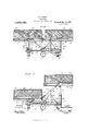
- FIG. 1 is a side elevation of my improved table truck with its sections horizony tally alined;
- Fig. 2 is a similar view showing one section raised and the other lowered during their movement to thevertical alined position;
- Fig. 3 is a longitudinal sectional view with the sections in vertically alined position
- Fig. 4 is a vertical transverse section taken substantially on line 4 4 of Fig. 3;
- Fig. 5 is a perspective view of the frame and movable parts with the tables removed;
- Fig. 6 is an lenlarged vertical section through one end with the parts in the position shown in Fig. 1;
- Fig. 7 is a detail horizontal section taken on line 7-7 of Fig. 6;
- Figs. 8 and 9 are ⁇ detail cross sections through one of the table sections respectively Vin upper and lower positions, and,
- Fig. 10 is a detailed perspective View of the latch of one of the table sections.
- each of the table sections 15 and 16 has a side rail 19, and along one end is provided with an vend rail 20, it being noted from Fig. 1 -in particular that these end rails are at relatively opposite ends of the two sections, although the side rails 19 are along the same sides thereof.
- the section 16 which for convenience of description 1 'will hereafter term the rear section, and that end of the 'truck frame below the same, the rear end of the truck, is provided longitudinally 'along its lower ysurface and yadjacent ⁇ its 'opposite side edges, with channel bars -21 disposed to open inwardly and adapted to receive therein the rollers 22 along the horizontally ⁇ exter'idir'ig arms 23 of an angular frame embodying in addition to these horizontal arms 23 vertical arms 24, as ⁇ most plainly seen in Fig. v5, which latter, vas seen in Figs. 6 and 7, have outstanding rollers 25 movably disposed in vertically arranged channel bars 26 rigidly secured to and upstanding from the rear end 'of the truck body 17, adjacent its opposite sides.
- the frame above mentioned which i'ncludes the horizontal 'and vertical portions 23 and 24 has rsuitable braces 27 and a lower cross bar 28 connects the lower ends of the vertical portions 24, and is pivota'lly connected adjacent its opposite ends with a pair of depending links 29, the functions of which will be presently made plain.
- the table section 16 is shiftable vertically by virtue of the movable engagement of the vertical arms 24 with the guide channels 26 of the truck, and is shiftable horizontally by virtue off the movable support thereofl upon the rollers 22 of the horizontal arms 28, it being obvious ⁇ from this that the section 16 will be held in horizontal position at all times.
- the sections 15 and 16 are respectively provided with laterally outstanding pins or rollers 30 and 31, those 'of the section 15 being adjacent its rear end, and those of the section 16 being substantially at the center thereof. rlhese pins or rollers engage the longitudinally slotted outer ends 32 and 33 of side bars 34 fulcrumed at a .central point at 35 at the upper ends of rigid uprights 36, upstanding from the sides of the truck body 17 at points intermediate the ends of the latter and suitably bracedin their connection therewith by braces 36, all as plainly seen by a comparison of Figs. 1, 2 and 5.
- the connections between the sections 15 and 16 by the side bars 34 thus provide for simultaneous movement of these sections either horizontally or vertically and in relatively opposite directions.
- the table section 15 has longitudinal channel bars 37, the channels in which are presented inwardly to form guides and for the reception of rollers 38 at the upper ends of the levers 39 fulcrumed to one another intermediate their ends as at 40, and as plainly seen in Fig. 5 to form a lazy tongs.
- the lower ends of certain of these levers have stationary pivots with the truck body 17 adjacent the forward end of the latter, the lower ends of the other levers having rollers 41 which are slidably disposed within parallel channel beams 42 of the truck body 17 alined belowv the channel beams 37 of the table section 15, as clearly seen in Fig.
- This lazy tongs arrangement obviously acts as a support for the table section 15, but more particularly as a support to maintain the same in horizontal position at all times for it is obvious that irrespective of their positions with regard to one another or inkrelation to truck 17 the table sections must be maintained in horizontal position or otherwise the material loaded thereon would be permitted to slide off of the same during their adjustment.
- the rear ends of these levers 43 are pivotally connected to the lower ends of the links 29 previously described, so that lowering movementV of the section 16 forces 'the rear ends L of theV levers 43 downwardly and forces their forward roller mounted ends upwardly to the supporting position in connection with Vtable section 15.
- the truck body 17 is of course provided with longitudinal slots, one
- the rear end of the latch rod 50 is pivotally connected to a latch hook 52 fulcrumed at the rear portion of the truck body, which latch hook is arranged to engage the lower crossbar 28 of the movable supporting frame of the table section 16 when the latter is lowered in the position of Fig. 1.
- channel bars 37 of the table section 15, as well as the channel bars A42l of thetruck body have relatively engageable side lrollers 53 and side railsv 54, which come into engagement in the manner particularly seen in Fig. 4, when the table section 15 is lowered to the position of Fig. 2, and which act during conversally sliding movement of the table Vsection 15 rearwardly from the position of to the other when loaded.
- the table section 16 carries upon its under surface a pair of longitudinally alined gravity latch bars 59 and 60, having overlapping extensions at 61 so that elevation of the outer end of the forward latch bar 16 will cause similar elevation of the inner end of the forward latch bar 59.
- These latch bars are notched to engage the cross bar 24 at the angle of the frame including the horizontal portions 23 and vertical 'portions 24 before described, respectively in the outer and inner positions of the said table section.
- the latch bar 60 In the inner position as seen in Fig. 3, the latch bar 60 is engaged as shown and must be disengaged before the table section 16 can be shifted forwardly upon the rollers 22.
- the latch bar 59 would be engaged with the cross bar 24a and must be released before table section 16 can be shifted horizontally from the position of Fig. 2 to the position of Fig. 3.
- a roller mounted support In a table truck, the combination of a roller mounted support, a table in sections, mvabl vertically and llilZ''Il-lally Wit/l1 1"@- spect to the said support, uprights adjacent one end 'of the support, an an'gulai' frame having vertical portions provided with rollers 'engaging the said uprights and having a horizontal portion provided with rollers engaged by one o'f the table sections, a pair of uprights intermediate the "ends "of 'the support, 'and levers fulcr'umed upon the la'tter uprights and having movable connection at their opposite ends with the said table sections, for the purpose described.
- a roller mounted Asupport movable vertically and horizontally with respect to the said support, uprights adjacent one end of the support, an angular frame having vertical portions provided with rollers engaging the said uprights and having a horizontal portion provided with rollers engaged by one of the table sections, a lazy tongs connecting the other table section to the relatively opposite end of the support, a pair of uprights intermediate the ends of the support, and levers fulcrumed upon the latter uprights and having movable connection at their opposite ends with the said table sections, for the purpose described.
- a table truck the combination of a roller mounted support, a table consisting of sections movable vertically and horizontally with respect to the said support, and having independent connection therewith, lever connections between the said table sections to constrain the same to movement in relatively opposite directions, means engageable with certain of the supporting connections of one of the table sections for locking the table sections in horizontally alined position, and other means engageable with the supporting connections of the other of said table sections for locking the table sections in vertically alined position.
- a roller mounted support a pair of table sections having independent supporting connections with the said support, limiting the same to movement vertically and horizontally in straight lines with respect to said support, connections between the said table sections whereby to cause their movement simultaneously in relatively opposite direc'- tion's, means for ⁇ locking the tvvo sections in horizontally alined position, and means for locking the said sections in vertically alined position.
- a roller mounted support having a horizontal body provided With longitudinal guide members and with uprights adjacent one ,end and at a point intermediate the ends thereof, a pair of table sections one of which has guides longitudinally thereof, a lazy tongs movably engaging the guides of the said table section and the said support, an angular frame having horizontal and vertical portions upon the former of which the other of vsaid tab-le sections is movably disposed and the latter: of which is movably engaged With the end uprights of the said support, and levers fulorumed upon the intermediate up-rights of the support and having mov-able connections at their opposite ends with the table sections, substantially as described.
Landscapes
- Life Sciences & Earth Sciences (AREA)
- Engineering & Computer Science (AREA)
- Geology (AREA)
- Mechanical Engineering (AREA)
- Structural Engineering (AREA)
- Handcart (AREA)
Description
S. C. DODSON.
TABLE TRUCK.
APPLlCATION FILED FEB. 28| 1918. 1,298,185. Patented Mar. 25,1919.
3 SHEETS-SHEET l.
f7# ZO 9 A9 Z0 A TTOR/VEVS S. C. DODSON.
TABLE TRUCK.
APPLICATION FILED FEB. 28. 91s.
1,298,185. y Patented Mar. 25,1919.
3 SHEETS--SHEET 3.
WTNESSES NVENT? /aI/Ifzzzal Qamsazz v @y vS.L1L[U].ll'.i C. DODSON, OF BALTIMORE, MARYLAND.
TABLE-TRUCK.
Specification of Letters Patent.
Patented Mar. 25, 1919.
Application led February 28, 1918. lSerial1111.219520.
To all whom t may concern.'
Be it known that I, SAMUEL C. DoDsoN, a citizen of the United States, and a resident of Baltimore, in the State of Maryland, have made certain new and useful Improvements in Table-Trucks, of which the following is a specification.
My present invention relates generally to trucks for transporting articles, and particularly to a partially collapsible truck for transporting merchandise of every description by manufacturers and wholesalers capable of use as a checking table, so as to avoid the necessity of transferring the goods, my object being the provision of certain improvements in table trucks such as illustrated and claimed in my Patent 1,149,995, granted August 10, 1915.
My present improvements, as will be appreciated from 'the description to follow, avoid the three section table truck of lmy patent, with the complicated compensating connections therebetween, and purpose a two-section truck which may be more readily and quickly operated and manipulated from one position to another, and will be stronger and more durable, and which will be generally more effective in connection with heavy loads.
In the accompanying drawings illustrating my present improvements, and to which reference is made in the following specilication Figure 1 is a side elevation of my improved table truck with its sections horizony tally alined;
Fig. 2 is a similar view showing one section raised and the other lowered during their movement to thevertical alined position; I
Fig. 3 is a longitudinal sectional view with the sections in vertically alined position;
Fig. 4 is a vertical transverse section taken substantially on line 4 4 of Fig. 3;
Fig. 5 is a perspective view of the frame and movable parts with the tables removed;
Fig. 6 is an lenlarged vertical section through one end with the parts in the position shown in Fig. 1;
Fig. 7 is a detail horizontal section taken on line 7-7 of Fig. 6;
Figs. 8 and 9 are `detail cross sections through one of the table sections respectively Vin upper and lower positions, and,
Fig. 10 is a detailed perspective View of the latch of one of the table sections.
Referring now to these `igures, the two sections of the 'table as proposed by my present improvements are respectively indicated at 15 and 1G, supported through suitable connections upon a portable truck frame whose main or body portion 17 is disposed horizontally and upon rollers or wheels 1S.
Along one side each of the table sections 15 and 16 has a side rail 19, and along one end is provided with an vend rail 20, it being noted from Fig. 1 -in particular that these end rails are at relatively opposite ends of the two sections, although the side rails 19 are along the same sides thereof.
The section 16, which for convenience of description 1 'will hereafter term the rear section, and that end of the 'truck frame below the same, the rear end of the truck, is provided longitudinally 'along its lower ysurface and yadjacent `its 'opposite side edges, with channel bars -21 disposed to open inwardly and adapted to receive therein the rollers 22 along the horizontally `exter'idir'ig arms 23 of an angular frame embodying in addition to these horizontal arms 23 vertical arms 24, as `most plainly seen in Fig. v5, which latter, vas seen in Figs. 6 and 7, have outstanding rollers 25 movably disposed in vertically arranged channel bars 26 rigidly secured to and upstanding from the rear end 'of the truck body 17, adjacent its opposite sides.
The frame above mentioned which i'ncludes the horizontal 'and vertical portions 23 and 24 has rsuitable braces 27 and a lower cross bar 28 connects the lower ends of the vertical portions 24, and is pivota'lly connected adjacent its opposite ends with a pair of depending links 29, the functions of which will be presently made plain.
Thus by virtue of the construction described, the table section 16 is shiftable vertically by virtue of the movable engagement of the vertical arms 24 with the guide channels 26 of the truck, and is shiftable horizontally by virtue off the movable support thereofl upon the rollers 22 of the horizontal arms 28, it being obvious `from this that the section 16 will be held in horizontal position at all times.
The sections 15 and 16 are respectively provided with laterally outstanding pins or rollers 30 and 31, those 'of the section 15 being adjacent its rear end, and those of the section 16 being substantially at the center thereof. rlhese pins or rollers engage the longitudinally slotted outer ends 32 and 33 of side bars 34 fulcrumed at a .central point at 35 at the upper ends of rigid uprights 36, upstanding from the sides of the truck body 17 at points intermediate the ends of the latter and suitably bracedin their connection therewith by braces 36, all as plainly seen by a comparison of Figs. 1, 2 and 5. The connections between the sections 15 and 16 by the side bars 34 thus provide for simultaneous movement of these sections either horizontally or vertically and in relatively opposite directions.
The table section 15 has longitudinal channel bars 37, the channels in which are presented inwardly to form guides and for the reception of rollers 38 at the upper ends of the levers 39 fulcrumed to one another intermediate their ends as at 40, and as plainly seen in Fig. 5 to form a lazy tongs. The lower ends of certain of these levers have stationary pivots with the truck body 17 adjacent the forward end of the latter, the lower ends of the other levers having rollers 41 which are slidably disposed within parallel channel beams 42 of the truck body 17 alined belowv the channel beams 37 of the table section 15, as clearly seen in Fig. 4.- This lazy tongs arrangement obviously acts as a support for the table section 15, but more particularly as a support to maintain the same in horizontal position at all times for it is obvious that irrespective of their positions with regard to one another or inkrelation to truck 17 the table sections must be maintained in horizontal position or otherwise the material loaded thereon would be permitted to slide off of the same during their adjustment.
The table 15 in its upper positionwhere it is horizontally alined with the section 16, as seenrin Fig. 1, is furtherV supported by side levers 43 intermediately fulcrumed at 44 upon lugs 45 upstanding from th'e'truck body 17 and havingrollers 46 at their forward ends which in the position stated, bear upwardly against the table section 15. The rear ends of these levers 43 are pivotally connected to the lower ends of the links 29 previously described, so that lowering movementV of the section 16 forces 'the rear ends L of theV levers 43 downwardly and forces their forward roller mounted ends upwardly to the supporting position in connection with Vtable section 15. To accommodate the rear ends ofthe levers 43 the truck body 17 is of course provided with longitudinal slots, one
of which is visible in Fig.5.
The forward ends of the levers 43justf a spring 51 permitting the latch bolt to Y yield rearwardly. The rear end of the latch rod 50 is pivotally connected to a latch hook 52 fulcrumed at the rear portion of the truck body, which latch hook is arranged to engage the lower crossbar 28 of the movable supporting frame of the table section 16 when the latter is lowered in the position of Fig. 1.
Thus to move the table sections from the horizontally alined position of Fig. 1 .to the vertically alined position of Fig. 3, it is first necessary to release the latch hook 52 from the cross bar 28, and then press downwardly upon table section 15, forcing table section 16 upwardly at the same time to the position shown in Fig. 2by virtue lof the connecting levers 34 and their connectionswith the table sections. When in the nosition shown in Fig. 2, either one or the other ofthe table sections may be grasped and shifted longitudinally so as to move both of said sections into substantial vertical alinement as in Fig. 3. i
It will further be observed that the channel bars 37 of the table section 15, as well as the channel bars A42l of thetruck body, have relatively engageable side lrollers 53 and side railsv 54, which come into engagement in the manner particularly seen in Fig. 4, when the table section 15 is lowered to the position of Fig. 2, and which act during orizontally sliding movement of the table Vsection 15 rearwardly from the position of to the other when loaded.
It is obvious that the construction proy vided by my present invention will be strongand durable, its strength providing for use of theapparatusY in connection with loads of considerable weight, such as for instance piled up'bolts of fabric and like material for the transportation of which from floor to floor of a building upon elevators the apparatus is particularly designed. In such use the table sections after being loaded and checked at the sending station,
whilein the horizontally alined position of Y Fig. 1, are adjusted to the vertically alined position of Fig. 3,`when the truck is rolled masses onto an elevator, Iand after Ibeing rolled 'olf of 'the elevator in snch position on 'the receiving floor may be again readily adjusted to the horizontally -alined position and checked at the receiving station.
ments 'of the table section 15 'in the 'raised posit-ion shown in Fig. 1, which would cause a constant bumping of this table se'c'tion with the table section 16, are avoided, 'although the arm 57, which comes into engagement with the stationary upright releasing plate 58 of the lower support, when the table sec'- tion 15 is lowered, provides for automatic release of the latch so that when lowered to the position of Fig. 2 the table section 15 will 1then :be freely shiftab-le Ilong'itudi'nally of the lower support. This is to be observed particularly by comparison of Figs. 8 and 9, the former of which shows the latch 55 in engaged position and the latter of which shows the latch is disengaged position with the table section 15 lowered.
By reference to Fig. 3 in particular, it will also be noted that the table section 16 carries upon its under surface a pair of longitudinally alined gravity latch bars 59 and 60, having overlapping extensions at 61 so that elevation of the outer end of the forward latch bar 16 will cause similar elevation of the inner end of the forward latch bar 59. These latch bars are notched to engage the cross bar 24 at the angle of the frame including the horizontal portions 23 and vertical 'portions 24 before described, respectively in the outer and inner positions of the said table section. In the inner position as seen in Fig. 3, the latch bar 60 is engaged as shown and must be disengaged before the table section 16 can be shifted forwardly upon the rollers 22. In the position seen in Fig. 1, the latch bar 59 would be engaged with the cross bar 24a and must be released before table section 16 can be shifted horizontally from the position of Fig. 2 to the position of Fig. 3. l
It is obvious in thus providing for the latching of the table sections in the several positions my invention obviates all danger of their accidental displacement in transportation upon elevators and the like, jolts and jars of which might otherwise serve to shift the table sections into engagement with adjacent movable or immovable articles in the course of its operation.
I claims-- y l 1. fa table truck, 'the 'combination of a roller mounted support, A'a table in sections, each `of which is fmovable re'c'tiline'arly in vertical and horizontal directions with `re spec't to the support, and levers ful'cru'med upon za portion of the said support and having movable connections at "opposite ends with the said table sections to constrain the lat-ter to movement i-'n relatively opposite directions.-
'2. In a table truck, the combination of a roller mounted support, a table in sections, mvabl vertically and llilZ''Il-lally Wit/l1 1"@- spect to the said support, uprights adjacent one end 'of the support, an an'gulai' frame having vertical portions provided with rollers 'engaging the said uprights and having a horizontal portion provided with rollers engaged by one o'f the table sections, a pair of uprights intermediate the "ends "of 'the support, 'and levers fulcr'umed upon the la'tter uprights and having movable connection at their opposite ends with the said table sections, for the purpose described.
8. In a table truck, the combination of a roller mounted Asupport, a table in' sections movable vertically and horizontally with respect to the said support, uprights adjacent one end of the support, an angular frame having vertical portions provided with rollers engaging the said uprights and having a horizontal portion provided with rollers engaged by one of the table sections, a lazy tongs connecting the other table section to the relatively opposite end of the support, a pair of uprights intermediate the ends of the support, and levers fulcrumed upon the latter uprights and having movable connection at their opposite ends with the said table sections, for the purpose described.
l. In a table truck, the combination of a roller mounted support, a table consisting of sections movable vertically and horizontally with respect to the said support, and having independent connection therewith, lever connections between the said table sections to constrain the same to movement in relatively opposite directions, means engageable with certain of the supporting connections of one of the table sections for locking the table sections in horizontally alined position, and other means engageable with the supporting connections of the other of said table sections for locking the table sections in vertically alined position.
5. In a table truck, the combination of a roller mounted support, a pair of table sections having independent supporting connections with the said support, limiting the same to movement vertically and horizontally in straight lines with respect to said support, connections between the said table sections whereby to cause their movement simultaneously in relatively opposite direc'- tion's, means for `locking the tvvo sections in horizontally alined position, and means for locking the said sections in vertically alined position.
`6. In a table truck, the combination of a roller mounted support having a horizontal body provided With longitudinal guide members and with uprights adjacent one ,end and at a point intermediate the ends thereof, a pair of table sections one of which has guides longitudinally thereof, a lazy tongs movably engaging the guides of the said table section and the said support, an angular frame having horizontal and vertical portions upon the former of which the other of vsaid tab-le sections is movably disposed and the latter: of which is movably engaged With the end uprights of the said support, and levers fulorumed upon the intermediate up-rights of the support and having mov-able connections at their opposite ends with the table sections, substantially as described. Y Y
7. In a table truck, the combination of a angular frame having horizontal and vertical portions upon the former of-vvhich the other of said table sections is movably disposed and the latter of which is movably en-y gaged With the end uprights of the said support, levers fulcrumed upon the intermediate uprights of the support and having movable connections at their opposite ends With the table sections, and levers intermediately fulcrumed upon the support and having rollers at one end for Vengagement With'the table section supported, bythe lazyv tongs, said last named levers having' connections at theiropposite ends With the movable frame of the other table section, for the purpose described. Y l SAMUEL C. DODSON.
Copies of this patent may. be obtained forve cents each, by` addressing the Commissioner of vIlatents, Washington, D. C.
Priority Applications (1)
| Application Number | Priority Date | Filing Date | Title |
|---|---|---|---|
| US21962018A US1298185A (en) | 1918-02-28 | 1918-02-28 | Table-truck. |
Applications Claiming Priority (1)
| Application Number | Priority Date | Filing Date | Title |
|---|---|---|---|
| US21962018A US1298185A (en) | 1918-02-28 | 1918-02-28 | Table-truck. |
Publications (1)
| Publication Number | Publication Date |
|---|---|
| US1298185A true US1298185A (en) | 1919-03-25 |
Family
ID=3365728
Family Applications (1)
| Application Number | Title | Priority Date | Filing Date |
|---|---|---|---|
| US21962018A Expired - Lifetime US1298185A (en) | 1918-02-28 | 1918-02-28 | Table-truck. |
Country Status (1)
| Country | Link |
|---|---|
| US (1) | US1298185A (en) |
Cited By (2)
| Publication number | Priority date | Publication date | Assignee | Title |
|---|---|---|---|---|
| US2458907A (en) * | 1944-08-02 | 1949-01-11 | Hoppe Boris | Serving combination |
| US2793693A (en) * | 1953-02-24 | 1957-05-28 | United States Steel Corp | Take-off equipment for plate shears |
-
1918
- 1918-02-28 US US21962018A patent/US1298185A/en not_active Expired - Lifetime
Cited By (2)
| Publication number | Priority date | Publication date | Assignee | Title |
|---|---|---|---|---|
| US2458907A (en) * | 1944-08-02 | 1949-01-11 | Hoppe Boris | Serving combination |
| US2793693A (en) * | 1953-02-24 | 1957-05-28 | United States Steel Corp | Take-off equipment for plate shears |
Similar Documents
| Publication | Publication Date | Title |
|---|---|---|
| US2947513A (en) | Hydraulic bumper jack | |
| US795147A (en) | Combined hand-truck and hoist. | |
| US1824201A (en) | Lift-truck | |
| NO143614B (en) | TRANSPORT VEHICLE. | |
| US1298185A (en) | Table-truck. | |
| US2176636A (en) | Truck | |
| US672152A (en) | Truck. | |
| US2615677A (en) | Pallet truck | |
| JP3696407B2 (en) | Stopper operation device for transport device | |
| US2685972A (en) | Casket van | |
| US993265A (en) | Truck. | |
| US2681202A (en) | Pallet truck | |
| US2908031A (en) | Retractable roller device | |
| US607329A (en) | The morris petebs co | |
| US2681712A (en) | Lift-truck | |
| US3331520A (en) | Freight pallet and carrier | |
| US2946460A (en) | Pack handling device | |
| US2234255A (en) | Load transfer apparatus | |
| US2402412A (en) | Typewriter table | |
| US715944A (en) | Combined ladder and scaffold. | |
| US644048A (en) | Step-ladder. | |
| US3416682A (en) | Combination lift truck, hand truck and floor dolly | |
| US2440325A (en) | Safety device for dumping vehicles | |
| US2438212A (en) | Combination ladder stool | |
| US1286861A (en) | Elevating-truck. |