US1298050A - Demountable rim for vehicle-wheels. - Google Patents
Demountable rim for vehicle-wheels. Download PDFInfo
- Publication number
- US1298050A US1298050A US15211217A US15211217A US1298050A US 1298050 A US1298050 A US 1298050A US 15211217 A US15211217 A US 15211217A US 15211217 A US15211217 A US 15211217A US 1298050 A US1298050 A US 1298050A
- Authority
- US
- United States
- Prior art keywords
- rim
- lugs
- beveled
- wheel
- band
- Prior art date
- Legal status (The legal status is an assumption and is not a legal conclusion. Google has not performed a legal analysis and makes no representation as to the accuracy of the status listed.)
- Expired - Lifetime
Links
Images

Classifications
-
- B—PERFORMING OPERATIONS; TRANSPORTING
- B60—VEHICLES IN GENERAL
- B60B—VEHICLE WHEELS; CASTORS; AXLES FOR WHEELS OR CASTORS; INCREASING WHEEL ADHESION
- B60B23/00—Attaching rim to wheel body
- B60B23/06—Attaching rim to wheel body by screws, bolts, pins, or clips
- B60B23/10—Attaching rim to wheel body by screws, bolts, pins, or clips arranged axially
Definitions
- the present improvements relate more specifically to the formation of the demount able rim so as to adapt it to seat on the wheel body, and to the construction of the clamping means for securing such rim in seated position.
- One object of the improvements is to provide a form of rim, specifically of clencher flange type, that may be mounted on on a wheel body interchangeably with a straight side rim of the same size.
- Another object is to simplify the construction and operation of the clamping device, atthe Same time insuring'the rim against distortion, and effectively locking the same in place on the wheel body
- Figure 1 is aside elevational view er a portion of a wheel showing :11 present improved demountable rim in p ace thereon;
- Fig. 2 is a transverse section thereof and of the adjacent portions of: the wheel body taken on the plane indicated by the line 2-2, Fig. 1;
- Fig. 3 is a side elevational view illustrating one of the clamping devices;
- Fig. 4a is a broken plan view of the portion of the rim designed to cooperate with such clamping device;
- Fig. 5 is a longitudinal section of such portion taken on the plane indicated by the line 5+5, Fig. 4;
- Fig. 6 is a transverse sectional view corresponding with that of Fig. 2, but showing amodification in con struction;
- Fig. 7 is likewise a cross-sectional view corre ponding with that of Fig. 2, but
- FIG. 8 is a side elevational view of the modified form of clamping device illustrated-in Fig. 7;
- Fig. 9 is asectional view of a detail taken on the plane indicated by the line 99,
- Fig. 7 Fig. 10 is a sectional view of another detail taken on the plane in- Fig. 7 ,
- Fig. 11 is an elevational view corresponding with Fig. 8, but showing the clamping device removed;
- Fig. 12 illustrates the preferred form of driving connection between the rim and wheel body, consisting of stamped up lugs on such rim and the tellyband on such wheel body. respectively.
- the wheel body is shown as of familiar type, comprising, in addition to the usual woodenhub, spokes 2 and wooden felly 3, an encircling telly-band 4, the rear or inner edge of which is turned upwardly to form an outwardly inclined flange 5.
- the rim 6, which is likewise of familiar construction, is adapted to seat with its one edge resting on such beveled flange, and is shown in Figs. 2 and 6 as adapted to receive a straight sided indlfi'erence, so far as concerns the principal features of interest herein disclosed.
- a plurality of devices of the sortlillustrated in detail in Figs. 2 and 3. or of the alternative forms of construction illustrated in Fig. 6, and in Figsl 7 and 8, respectively, areprovided, these devices being spaced circularly about the felly, in such number as may be required.
- a clampplate 7 carried by a nut 8 mounted on the end of a bolt 9 that is transversely disposed in the folly 3 with its head 10 engaging the rear sideof the folly-band.
- Thecl-amp-plate is preferably rotatably secured to the tubular sleeve-like extension on the nut, the-inner end of which -is peened 0r spun up to form a with the outer surface of the felly-band, fitting in the space between the latter and the inner surface of the rim, when said rim is in complementary to the beveled projection on said clamping plate.
- stamped-up beveled lugs have their inner faces more sharply inclined in the opposite direction, and come close enough to contacting with the felly-band to serve as centering means for the rim; that is, as the rim is moved transversely of the wheel body with its rear edge in seated position on the flange, these lugs ride up on the frontuedge of the fell)- band and force the rim into approximately true circular shape if it be slightly distorted under the stress of the air-pressure in the inflated tire carried thereby.
- the felly-band 1 is shown with a. somewhat, difierent form of flange 17 on its rear edge, and in order to accommodate the rim ti thereto the latter is provided with integral stamped-up beveled lugs 18 in circmnferentially spaced relation around its inner edgeas well as with lugs 19 similar to those previously described around its outer edge.
- the beveled faces of the lugs 18 incline in av direction corresponding with the inclination of the flange 17 and seat firmly thereon, when the rim is in place.
- a modification in the form of the clamp-plate 20 is also shown in that the lower project-ion is omitted.
- the beveled projection isdesigned to move in a strictly rectilinear direct-ion parallel with the axis of the bolt, instead of in the oscillatory fashion characteristic of the clamping wedges used in connection with the familiar Continental t-ype-demountable rim. Besting, as the beveled projections do, flatly on th felly-band, there is no tendency for them to bend the ends of the bolts, as frequently occurs in the type of rim just mentioned, and the accurate centering of the rim is notdisturbed, while at the same time an effective locking action is secured.
- I preferably stamp up radial projections 2i on the fellyband 1. integral therewith. and having their outer faces beveled so that the rim will ride up onto them as it is shoved into place on the wheel body.
- the circumferential extent of these lugs may be varied as found desirable.
- a preferred form of driving connection between the rim and felly-band such as is particularly adapted for use with a rim of the form illustrated in Fig. 1. which is not reversible.
- a rim obviously requires to be placed on the wheel body with the side having the beveled lugs turned outwardly. Accordingly.
- such lugs being of the integral stamped up form shown and described in Patent No. 1.153.182 to R. S. Bryant. with their juxtaposed, shouldered faces 26 converging toward the inner edge of the felly-band.
- the driving lug 27 on the rim which is similarly stamped-up integrally from the material of such rim, is formed with complementary angularly related shoulders '28, so that the rim can only be placed on the wheel-body when the smaller end of such lug is directed inwardly, as will be readily understood.
- a wheel-body In a vehicle wheel. the combination of a wheel-body; a telly-band surrounding the same having a. transversely beveled. out-- wardly inclined flange of curved cross-section along itsone edge; a rim adapted to wheel-body, with inwardly projecting lugs adjacent its re spective sides. the lugs along one side being curved transversely to correspond and engage with the flan on said.
- felly-band and transversely mova 1e clamps on said wheelbody having port-ions adapted to engage along the otherside of said rim.
- ha wing comple wheel-body with same having a transversely beveled, out I wardly inclined flange of curved cross-section along its one edge; a rim adapted to seat demountably on said beveled lugs adjacent its respective sides, the lugs along one side being curved transversely to correspond-and engage with the flangeon said telly-band; and transversely movable clamps on said wheel-body having complementary beveled portions adapted to engage with the lugs along the other side of said rim'.
- a wheel-body a felly-band surrounding the same having a transversely beveled, outwardly inclined flange along its one edge; a rim adapted to seat demountably on said inwardly projecting, out wardly inclining beveled lugs adjacent its respective sides, the lugs along one side being adapted to engage with the flange on said telly-band; and transversely movable clamps in said wheel-body having complementary beveled portions adapted to engage with the lugs along the other side of said rim .but otherwise entirely to clear said rim.
- a wheel-body a feIly band surrounding the same having a transversely beveled, outwardly inclined flange along its one edge; a. rim adapted to seat demountably on said wheeLbody, with inwardly projecting. out wardly inclining beveled lugs adjacent its respective sides, the lugs along one side being adapted to engage with the flange on said felly'ba-nd: transversely disposed bolts on said wheel-body; nuts on said bolts; and clamp-plates carried by said nuts having beveled projections complementary to and adaptedto engage. with the lugs along the other side of said rim.
Landscapes
- Engineering & Computer Science (AREA)
- Mechanical Engineering (AREA)
- Tires In General (AREA)
Description
O. H. IOBSKI.
DEMOUNTABLE RIM FOR VEHICLE WHEELS.
APPLICATION FILED MAR. 2. I917.
1,298,050. Patented Mar. 25,1919.
2 SHEETSSHEET l.
hvvavroa 0775 m/om /r/ irToa/wz w 0. H. JOBSKI.
DEMOUNTABLE RIM FOR VEHICLE WHEELS,
APPLICATION FILED MAR. 2. 1917.
1 98,050 Patented M125, 1919.
2 SHEETSSHEET 2.
TTOBNE Yo UNIED STATES PATENT @FFICE.
orro n. JoBsK 'or cLEvn-rnn'n, OHIO, assrelvori To THE STANDARD PARTS COMPANY, or CLETELAND, care, a conronarron or OHIO.
nnmou'n'raatn am non VEHICLE-WHEELS.
Specification of Letters Patent.
- Patented Mar. 25, 1919 Application filed March 2, 1917. Serial No. 152,112.
To all whom it may concern:
Be it known that I. O'l'ro H. JOBSKI, a citizen of the United States, and a resident of Cleveland, county of Cuya-hoga', and State of Ohio, have invented a new and useful Improvement inDemountable Rims for Vehic-le-Wheels, of which the following is a specification, the principle of the invention being herein explained and the best mode in which I have contemplated applying that principle, so as to distinguish it from other inventions. g
The present improvements relate more specifically to the formation of the demount able rim so as to adapt it to seat on the wheel body, and to the construction of the clamping means for securing such rim in seated position. One object of the improvements is to provide a form of rim, specifically of clencher flange type, that may be mounted on on a wheel body interchangeably with a straight side rim of the same size. Another object is to simplify the construction and operation of the clamping device, atthe Same time insuring'the rim against distortion, and effectively locking the same in place on the wheel body To the accomplishment of the foregoing and related ends, the invention, then, consists of the means hereinafter fully describediand particularly pointed out in the claims. r
The annexed drawings and the following description set forth in detail certain mechanism embodying the invention, such disclosed means constituting, however, but one of various mechanical forms in which the principle of the inventlon may be used.
In said annexed drawings Figure 1 is aside elevational view er a portion of a wheel showing :11 present improved demountable rim in p ace thereon; Fig. 2 is a transverse section thereof and of the adjacent portions of: the wheel body taken on the plane indicated by the line 2-2, Fig. 1; Fig. 3 is a side elevational view illustrating one of the clamping devices; Fig. 4a is a broken plan view of the portion of the rim designed to cooperate with such clamping device; Fig. 5 is a longitudinal section of such portion taken on the plane indicated by the line 5+5, Fig. 4; Fig. 6 is a transverse sectional view corresponding with that of Fig. 2, but showing amodification in con struction; Fig. 7 is likewise a cross-sectional view corre ponding with that of Fig. 2, but
dicated by the line 1010,
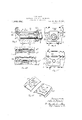
tire, although this is obviously a matter of illustrating still another modification in construction; Fig. 8 is a side elevational view of the modified form of clamping device illustrated-in Fig. 7; Fig. 9 is asectional view of a detail taken on the plane indicated by the line 99, Fig. 7 Fig. 10 is a sectional view of another detail taken on the plane in- Fig. 7 ,Fig. 11 is an elevational view corresponding with Fig. 8, but showing the clamping device removed; while Fig. 12 illustrates the preferred form of driving connection between the rim and wheel body, consisting of stamped up lugs on such rim and the tellyband on such wheel body. respectively.
The wheel body is shown as of familiar type, comprising, in addition to the usual woodenhub, spokes 2 and wooden felly 3, an encircling telly-band 4, the rear or inner edge of which is turned upwardly to form an outwardly inclined flange 5. The rim 6, which is likewise of familiar construction, is adapted to seat with its one edge resting on such beveled flange, and is shown in Figs. 2 and 6 as adapted to receive a straight sided indlfi'erence, so far as concerns the principal features of interest herein disclosed.
For supporting the front edge of the rim and securing the same with its rear edge in seated position on the aforesaid flange. a plurality of devices of the sortlillustrated in detail in Figs. 2 and 3. or of the alternative forms of construction illustrated in Fig. 6, and in Figsl 7 and 8, respectively, areprovided, these devices being spaced circularly about the felly, in such number as may be required.
Referring. first of all, to the specific form of such device illustrated in Figs. 2 and 3, the same will be seen to consist of a clampplate 7 carried by a nut 8 mounted on the end of a bolt 9 that is transversely disposed in the folly 3 with its head 10 engaging the rear sideof the folly-band. Thecl-amp-plate is preferably rotatably secured to the tubular sleeve-like extension on the nut, the-inner end of which -is peened 0r spun up to form a with the outer surface of the felly-band, fitting in the space between the latter and the inner surface of the rim, when said rim is in complementary to the beveled projection on said clamping plate. These stamped-up beveled lugs have their inner faces more sharply inclined in the opposite direction, and come close enough to contacting with the felly-band to serve as centering means for the rim; that is, as the rim is moved transversely of the wheel body with its rear edge in seated position on the flange, these lugs ride up on the frontuedge of the fell)- band and force the rim into approximately true circular shape if it be slightly distorted under the stress of the air-pressure in the inflated tire carried thereby.
It will be observed that. as shown in Fig. 2. the transverse extent of the depressions 15 formed in the bottom of the rim by the stamped-up lugs. is less than that of the corresponding bead 16 of the tire shoe carried by the rim. In other words, these depressionsare entirely covered over by such bead. and any danger of the inner tube either blowing out or becoming pinched in such depressions is thus obviated.
In Fig. 6, the felly-band 1 is shown with a. somewhat, difierent form of flange 17 on its rear edge, and in order to accommodate the rim ti thereto the latter is provided with integral stamped-up beveled lugs 18 in circmnferentially spaced relation around its inner edgeas well as with lugs 19 similar to those previously described around its outer edge. The beveled faces of the lugs 18 incline in av direction corresponding with the inclination of the flange 17 and seat firmly thereon, when the rim is in place. A modification in the form of the clamp-plate 20 is also shown in that the lower project-ion is omitted.
In this second form of clamping device, as well as that shown in Fig. 2, the beveled projection isdesigned to move in a strictly rectilinear direct-ion parallel with the axis of the bolt, instead of in the oscillatory fashion characteristic of the clamping wedges used in connection with the familiar Continental t-ype-demountable rim. Besting, as the beveled projections do, flatly on th felly-band, there is no tendency for them to bend the ends of the bolts, as frequently occurs in the type of rim just mentioned, and the accurate centering of the rim is notdisturbed, while at the same time an effective locking action is secured.
In the construction illustrated inFigs. T to 11. inclusive. still another form of beveled flange 21 is shown on the rear edge of the telly-band 1". such flange having more of a cm'ved effect than the two shown in Figs. 2 and 6 respectively, such as is adapted to cooperate with a straight side rim, but notwith a clencher flange rim. However, by forming such clencher flange. rim 6 with integral stamped-up lugs 22 having rounded beveled faces instead of flat beveled faces, in the preceding forms. the clencher rim may be equally securely seated on such a folly-band. The clamping plates 23 employed in connection with this construction. however, instead of having projections that enter into the space between the rim and felly-band, extend out far enough to engage with the adjacent rounded beveled lugs '22 and exert principally a lateral clamping action'with less of the wedging effect than in the case of the other designs.
In order to insur the accurate centering of the rim in this construction. I preferably stamp up radial projections 2i on the fellyband 1. integral therewith. and having their outer faces beveled so that the rim will ride up onto them as it is shoved into place on the wheel body. The circumferential extent of these lugs may be varied as found desirable.
In Fig. 12. as previously indicated. there is shown a preferred form of driving connection between the rim and felly-band such as is particularly adapted for use with a rim of the form illustrated in Fig. 1. which is not reversible. In other words, such rim obviously requires to be placed on the wheel body with the side having the beveled lugs turned outwardly. Accordingly. I dispose the driving lugs 25 on the felly-band. such lugs being of the integral stamped up form shown and described in Patent No. 1.153.182 to R. S. Bryant. with their juxtaposed, shouldered faces 26 converging toward the inner edge of the felly-band. The driving lug 27 on the rim, which is similarly stamped-up integrally from the material of such rim, is formed with complementary angularly related shoulders '28, so that the rim can only be placed on the wheel-body when the smaller end of such lug is directed inwardly, as will be readily understood.
Other modes of applying the principle of my invention may be employed instead of the one explained, change being made as regards the mechanism herein disclosed, provided the means stated by any of the following claims or the equivalent of such stated means be employed.
I therefore particularly point out' and distinctly claim as my invention 1. In a vehicle wheel, the combination with a wheel body and a rim adapted to seat demountably thereon; of means adaptseat demountably on said with the lugs ed to secure said rim in tion, said means including integral, stamped up beveled lugs projecting inwardly toward the same and transversely movable clamps on said wheel-body having complementary beveled portions adapted to engage with said 111 dn a. vehicle wheel, the combination with a wheel body and a rim adapted to seat demountably thereon; of means adapted to secure said rim in such seated position, said means including integral, stamped up beveled lugs projecting inwardly from said rim and inclining ou wardly to ward the same and transversely movable clamps on said wheel-body mentary' beveled portions adapted to engage with said lugs, but otherwise entirely to clear said rim.
3. In'a vehicle wheel, the combination with a wheel body and a rim adapted to seat demountably thereon; of means ada-pt ed to secure said rim in such seated position, saidmeans including integral, stamped-up beveled lugs projecting inwardly from said rim and inclining outwardly toward the same. transversely disposed bolts in said wheel-body, nuts on said bolts, and clampplates carried by. said nuts having beveled projections complementary to and adapted to engage with said lugs. I
,4. In a vehicle wheel. the combination of a wheel-body; a telly-band surrounding the same having a. transversely beveled. out-- wardly inclined flange of curved cross-section along itsone edge; a rim adapted to wheel-body, with inwardly projecting lugs adjacent its re spective sides. the lugs along one side being curved transversely to correspond and engage with the flan on said. felly-band: and transversely mova 1e clamps on said wheelbody having port-ions adapted to engage along the otherside of said rim.
- 5. In a vehicle wheel, the combination of a wheel-body; a telly-band surrounding the such seated posiinwardly projecting,
ha wing comple wheel-body, with same having a transversely beveled, out I wardly inclined flange of curved cross-section along its one edge; a rim adapted to seat demountably on said beveled lugs adjacent its respective sides, the lugs along one side being curved transversely to correspond-and engage with the flangeon said telly-band; and transversely movable clamps on said wheel-body having complementary beveled portions adapted to engage with the lugs along the other side of said rim'.
6. In a vehicle wheel, the combination of a wheel-body a felly-band surrounding the same having a transversely beveled, outwardly inclined flange along its one edge; a rim adapted to seat demountably on said inwardly projecting, out wardly inclining beveled lugs adjacent its respective sides, the lugs along one side being adapted to engage with the flange on said telly-band; and transversely movable clamps in said wheel-body having complementary beveled portions adapted to engage with the lugs along the other side of said rim .but otherwise entirely to clear said rim.
7. In a vehicle wheel, the combination of a wheel-body; a feIly band surrounding the same having a transversely beveled, outwardly inclined flange along its one edge; a. rim adapted to seat demountably on said wheeLbody, with inwardly projecting. out wardly inclining beveled lugs adjacent its respective sides, the lugs along one side being adapted to engage with the flange on said felly'ba-nd: transversely disposed bolts on said wheel-body; nuts on said bolts; and clamp-plates carried by said nuts having beveled projections complementary to and adaptedto engage. with the lugs along the other side of said rim.
Signed by me, this 26th day of February, 1917.
, OTTO H. JOBSKI.
so wheel-body, with} outwardly inclining
Priority Applications (1)
| Application Number | Priority Date | Filing Date | Title |
|---|---|---|---|
| US15211217A US1298050A (en) | 1917-03-02 | 1917-03-02 | Demountable rim for vehicle-wheels. |
Applications Claiming Priority (1)
| Application Number | Priority Date | Filing Date | Title |
|---|---|---|---|
| US15211217A US1298050A (en) | 1917-03-02 | 1917-03-02 | Demountable rim for vehicle-wheels. |
Publications (1)
| Publication Number | Publication Date |
|---|---|
| US1298050A true US1298050A (en) | 1919-03-25 |
Family
ID=3365593
Family Applications (1)
| Application Number | Title | Priority Date | Filing Date |
|---|---|---|---|
| US15211217A Expired - Lifetime US1298050A (en) | 1917-03-02 | 1917-03-02 | Demountable rim for vehicle-wheels. |
Country Status (1)
| Country | Link |
|---|---|
| US (1) | US1298050A (en) |
Cited By (1)
| Publication number | Priority date | Publication date | Assignee | Title |
|---|---|---|---|---|
| US20180072380A1 (en) * | 2015-06-26 | 2018-03-15 | Specialized Bicycle Components, Inc. | Ebike battery with integral control panel |
-
1917
- 1917-03-02 US US15211217A patent/US1298050A/en not_active Expired - Lifetime
Cited By (1)
| Publication number | Priority date | Publication date | Assignee | Title |
|---|---|---|---|---|
| US20180072380A1 (en) * | 2015-06-26 | 2018-03-15 | Specialized Bicycle Components, Inc. | Ebike battery with integral control panel |
Similar Documents
| Publication | Publication Date | Title |
|---|---|---|
| US1298050A (en) | Demountable rim for vehicle-wheels. | |
| US1593886A (en) | Wheel and demountable rim | |
| US1342622A (en) | Vehicle-wheel | |
| US974713A (en) | Vehicle-wheel tire and rim. | |
| US1235537A (en) | Vehicle-wheel rim. | |
| US1219064A (en) | Vehicle-wheel rim. | |
| US1649772A (en) | Wheel and demountable rim | |
| US1136985A (en) | Vehicle wheel-rim. | |
| US1377162A (en) | Disk wheel | |
| US1134740A (en) | Demountable wheel-rim. | |
| US1440190A (en) | Demountable rim construction | |
| US1372230A (en) | Demountable rim for wheels | |
| US940602A (en) | Vehicle-wheel rim. | |
| US1504689A (en) | Vehicle wheel | |
| US977844A (en) | Rim for tires of motor-vehicle wheels. | |
| US1038372A (en) | Detachable rim for vehicle-wheels. | |
| US1160254A (en) | Vehicle-wheel. | |
| US925908A (en) | Wheel for road-vehicles. | |
| US1024746A (en) | Demountable wheel-rim. | |
| US1336531A (en) | Vehicle-wheel with demountable rim | |
| US871460A (en) | Rim for vehicle-wheels. | |
| US1391806A (en) | Products | |
| US1063648A (en) | Demountable rim for vehicle-wheels. | |
| US1368669A (en) | Demountable-rim fastening | |
| US827494A (en) | Vehicle-wheel. |