US1292002A - Sheet-delivery mechanism for printing-presses and other machines. - Google Patents
Sheet-delivery mechanism for printing-presses and other machines. Download PDFInfo
- Publication number
- US1292002A US1292002A US23467018A US23467018A US1292002A US 1292002 A US1292002 A US 1292002A US 23467018 A US23467018 A US 23467018A US 23467018 A US23467018 A US 23467018A US 1292002 A US1292002 A US 1292002A
- Authority
- US
- United States
- Prior art keywords
- sheet
- path
- tape
- chain
- elements
- Prior art date
- Legal status (The legal status is an assumption and is not a legal conclusion. Google has not performed a legal analysis and makes no representation as to the accuracy of the status listed.)
- Expired - Lifetime
Links
- 230000007246 mechanism Effects 0.000 title description 74
- 238000012384 transportation and delivery Methods 0.000 title description 32
- 230000008093 supporting effect Effects 0.000 description 88
- 230000015572 biosynthetic process Effects 0.000 description 55
- 238000005755 formation reaction Methods 0.000 description 55
- 230000000875 corresponding effect Effects 0.000 description 17
- 238000010276 construction Methods 0.000 description 9
- 230000000694 effects Effects 0.000 description 7
- 239000011435 rock Substances 0.000 description 7
- 230000007306 turnover Effects 0.000 description 7
- 230000006835 compression Effects 0.000 description 5
- 238000007906 compression Methods 0.000 description 5
- 230000002596 correlated effect Effects 0.000 description 4
- 230000006870 function Effects 0.000 description 2
- 229920000136 polysorbate Polymers 0.000 description 2
- PPKXEPBICJTCRU-XMZRARIVSA-N (R,R)-tramadol hydrochloride Chemical compound Cl.COC1=CC=CC([C@]2(O)[C@H](CCCC2)CN(C)C)=C1 PPKXEPBICJTCRU-XMZRARIVSA-N 0.000 description 1
- WKBPZYKAUNRMKP-UHFFFAOYSA-N 1-[2-(2,4-dichlorophenyl)pentyl]1,2,4-triazole Chemical compound C=1C=C(Cl)C=C(Cl)C=1C(CCC)CN1C=NC=N1 WKBPZYKAUNRMKP-UHFFFAOYSA-N 0.000 description 1
- 241000837181 Andina Species 0.000 description 1
- 230000009471 action Effects 0.000 description 1
- 230000008901 benefit Effects 0.000 description 1
- 229910052729 chemical element Inorganic materials 0.000 description 1
- 230000006872 improvement Effects 0.000 description 1
- 230000013707 sensory perception of sound Effects 0.000 description 1
- 230000035939 shock Effects 0.000 description 1
- 230000000153 supplemental effect Effects 0.000 description 1
Images


Classifications
-
- B—PERFORMING OPERATIONS; TRANSPORTING
- B65—CONVEYING; PACKING; STORING; HANDLING THIN OR FILAMENTARY MATERIAL
- B65H—HANDLING THIN OR FILAMENTARY MATERIAL, e.g. SHEETS, WEBS, CABLES
- B65H15/00—Overturning articles
Definitions
- ROBERT MIEHLE OF CHICAGO
- ILLINOIS ILLINOIS
- My invention relates to sheet delivery mechanisms for printing presses and other machines, and certain features thereof relate to a mechanism of the type disclosed in my I S. Patent No. 1,111,667, granted September 22, 1914, embracing a delivery mechanism moving outwardly on one level during its receipt of the sheet, and descending to a lower level and moving inwardly to effect the discharge of the sheet.
- a pusher element adapted to engage the tail end of the sheet when on said lower level to discharge the sheet from the sheet supporting element or tape stretch, which pusher element is conveniently supported below the lower level whereby its support ing means may be of the simplest nature, and whereby the pusher element may be made adjustable in the line of travel of the sheet so that various sizes of sheets may be delivered and piled on the receiving table at a convenient point below the outer end of the delivery mechanism.
- a supplemental feature of this resides in providing a pusher mechanism which is resiliently yieldable in the line of travel of the sheet driving and supporting means of the sheet supporting element, while on said lower level, and out of the path thereof to allow the same to pass through said lower level without interference.
- This resiliently yieldable feature also preferably obtains in the pusher mechanism in a direction oppo- Specification of Letters Patent.
- a further feature resides in providing cushioning means for the pusher element to cushion the movement of the same into normal sheet engaging position whereby the noise and shock of the pusher element reaching normal position is minimized.
- I provide simple means for driving and supporting a sheet delivery mechanism which is adapted to have assembled thereon a printed-side-up delivery or a printed-side-down, or turn-over, easily andquickly.
- I provide a mechanism for connecting the sheet engaging elements of the deliveries which. while easily assembled and disassembled, provides a strong connection well adapted to perform its functions within a relatively limited space.
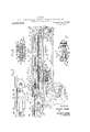
- Figure 1 is a sectional side elevation of a sheet delivery mechanism embodying my invention.
- Fig. 2 is a continuation of Fig. 1 at the left end thereof.
- Fig. 3 is a partial top plan view of the mechanism illustrated in Fig. 1.
- Fig. at is a partial end elevation of the mechanism illustrated in Figs. 1 and 3.
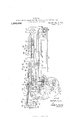
- Fig. 5 is a sectional side elevation of the mechanism, similar to Fig. 1, showing a printed-side-down delivery assembled with the supporting and driving mechanism of the device.
- FIG. 6 is a sectional side elevation of the supporting and driving mechanism alone.
- Fig. 10 is a section in end elevation of the same.
- FIG. 11 is a sectionalview in end elevation on the line 1111 of Fig. 6.
- V Fig. 12 is a similar view showing the bearer of the printed-side-up delivery mounted thereon as hereinafter described.
- the sheets are initially carried from the press upon thc'carrying tapesl.
- the outer ends of said tapes are supported upon pulleys 2 which are secured upon a shaft 3,
- the main frames 5 are disposed one upon either side of the machine and studs 6 are mounted therein which support the outer end of the frames 4.
- Each frame 5 has two holes, an upper hole 6 and 'a lower hole '6 for engagement with the respective studs 6, and by inserting the stud 6 into one or the other pair of holes, the frames 1, and consequently the tapes 1, may be supportedin two levels for purposes hereinafter to' be described.
- Sheet guides 7 are supported upon the frames 1 through means hereinafter to be more fully described and are disposed at intervals between the tapes 1 and extend outwardly of the pulleys 2 to guide the sheet to the delivery mechanism proper.
- the stud shaft 8 is mounted for rotation in an adjustable bracket 9, which is secured upon the right hand frame 5, and a sprocket 11 is fixedly mounted upon the stud shaft 8, and in conjunction with a chain 12, which is in driven connection with the press mechanism, serves to'drive said shaft in'a counter-clockwise direction as indicated by the arrow in Fig. 1.
- a shaft 13 is mounted for rotation in the frames 5 and extends across the space between the same and the ends thereof project beyond their respective frames'5.
- sprocket 14 is fixedly mounted upon the right hand end of the shaft 13, and a corresponding sprocket 15 is ,fixedly mounted upon the stud shaft 8, and a chain 16 is trained over said sprockets 14 and 15 to provide a driving connection therebetween.
- said shaft 13 rotates in a counterclockwise direction when shaft 8 is rotated in a counter -clockwise direction as before described;
- a spur gear 17 is fixedly mounted upon the shaft. 13 exteriorly of the right hand frame 5, and a gear similar to gear 17 is fixedly mounted upon a shaft 13 on the outside of the other frame 5.
- the driving mechanism for the sheet delivery mechanism proper of my invention is driven from the gear 17 and its corresponding gear upon the opposite side of the machine. This driving mechanism is exactly the same upon either side of the machine, and for that reason only one mechanism has been shown,
- the stud shaft 18 which has a spur gear 19 fixedly mounted thereon exteriorly of the frame 5 and meshing with the gear 17.
- the stud shaft 18 extends through the frame 5 and has a sprocket 20 fixedly mounted thereon on the inside of said frame'5 and closely adjacent thereto.
- the frame 5 has an extension 21 projecting outwardly therefrom, and a sprocket or wheel 22 is mounted forrotation upon a stud 23 disposed outwardly of said sprocket 20 at a point about midway between the ends of the extension 21, said sprocket 22 being, in lateral alinement with the sprocket 20 and having its axis parallel to that of said sprocket.
- a second sprocket or wheel 24 is mounted at the outer end of the extension 21 upon a stud 25 for rotation, said sprocket 24: being in lateral alinement with the sprockets 22 and 20 and having its axis parallel to that of said sprockets and disposed in a common line passing through the axes of the sprockets 20 and 22.
- the studs 23 and 25 are mounted upon the exten sion 21, of the frame 5, and the frame 5 constitutes the support for all three sprockets.
- the axes of the sprockets 20, 22, and 24 are preferably disposed in a common line, and they are preferably all of the same size, whereby a chain trained over the sprocket 20, which maybe termed the driving sprocket, and the sprocket 22 will have the stretches thereof extending in the same plane as would a chain trained over the drive sprocket 20 and the sprocket 24.
- an endless chain 26 is trained over the driving sprocket 20 and the outer sprocket V 24, and the stretches of said chain pass over the middle sprocket 22 without interference.
- the gear 17 rotates in a counter-clockwise direction and drives the sprocket 20 through the gear 19 in a clockwise direction, as indicated by the arrow in Fig. 1 whereby the upward stretch of the chain 26 moves outwardly and the lower stretch thereof moves inwardly.
- the other frame 5 has an extension similar to extension 21 and is disposed in parallelism therewith, and the driving mechanism upon the opposite side of the machine is similar to that just described and embraces a chain similar to driving.
- chain 26 having the same orbit of travel and disposed in a plane parallel thereto.
- rod structures 27 Extending across the space between the driving chains and having their respective ends carried by said chains at corresponding points are a pair of rod structures 27 These rod structures divide the driving chains into two equal parts and-are moved by said chains in a closed path outwardly, turning back, and moving inwardly as to said driving chains.
- a p1u rality of tape engaging elements 28 are rotatably mounted upon respective rod structures 27 at intervals along the transverse extent of the same between the driving chains 26.
- the tape engaging elements of each rod structure have their free.
- the tape engaging elements 28 may be secured in any adjustment along the respective transverse element 29 by means. of set screws 30 screw threaded into each tape engaging element and adapted to engage the respective transverse element 29 to clamp the tape engaging elements thereon.
- These cam elements are mounted upon respective rod structures 27 between pairs of lateral thrust collars 33 secured upon the respective rod structures 27, whereby the transverse supporting elements 29 are prevented from longitudinal movement relatively to their respective rod structures 27.
- transverse supporting elements 29 are spaced from the adjacent chains26, within the space between the same, and are provided 'with supporting rollers 34 rotatably mounted thereon. meansofthis construction the free end of the tape engaging element 28, and thetransverse supporting element 29 are allowed movement transversely of the path of the driving-chain 26.parall el to the plane of the inclosure of said chain.
- the free end of the tape engaging element 28 and the transverse supporting element 29 are positioned in front of the respective rod structures 27 relatively to the direction of movement, and by reason of the fact that the axes of said tape engaging elements 28 are positioned behind the free ends thereof, said free ends and the transverse supporting element 29 may have an arcual movement transversely of the path of the drivingchain as above described and inclining rearwardly relatively to the direction of travel.
- the supporting rollers 34 are supported by a bearer 35, which is formed upon the extension frame 21 while moving outwardly along the upper stretch of the chain 26, and are supported by a bearer 36, which is mounted upon the extension 21 whilemoving inwardly along the lower stretch of said chain.
- rollers 34L are generally similar to that of the rod structures 27 and the chain 26, but differs therefrom during certain periods in the cycle ashereinafter to be described.
- a bracket 37 is aflixed to the outside of each extension frame 21, and extends through an opening in the respective extension frame 21, just in front of the respective drive sprocket 20, and between the stretches of the chain 26, and has a rear- Wardly extending portion, disposed on the inside of the respective sprocket 20, which terminates in a transverse bearing disposed coaxially with the respective drive sprocket 20.
- a yoke structure or bight forming means 38 is mounted for rotation in said transverse bearings. This yoke structure has a plurality of pairs of bight forming elements 39 mounted thereon, each pair of bight forming elements being in line with a respective pair of sheet engaging elements 28.
- These bight forming elements are preferably in the form of rollers rotatably mounted upon axes disposed parallel to the axis of the bight forming means 38, the bight forming elements of each pair being disposed in spaced relation and in lateral alinement with each other and having their axes disposed on opposite sides of the axis of the bight forming means 38.
- a tape stretch 40 is provided for eachpair of bight forming elements 39 and respective sheet engaging elements 28, in a manner to be hereinafter more fully described, and passes through the space between the respective pair of bight forming elements 39.
- These tape stretches are preferably formed of closely coiled wire.
- Each sheet engaging element 28 has two convex arcuate formations ll facing each 7 other and converging to form a throat, these ing said end of the tape stretch within said bore.
- the tape stretch extends from said bore and is adapted to be wrapped on either of said formations. As the mechanism is operated the tape stretches 40 are wrapped about the arcuate formations of the tape on gaging elements 28,which extend inwardly toward the bight forming means 88 as the tape engaging elements 28 move outwardly along the upper stretch of the chain 26.
- This construction reduces the amount of elasticity required in the tape stretch as said tape engaging elements pass around the ends of their path, by reason of the fact that as said tape engaging elements pass around the end of their path, the tape is unwrapped from the engaged arcuate formations and the length which was wrapped around said arcuate formations forms a part of the stretch of the tape prior to its being engaged with the opposite arcuate formation.
- this construction permits of the sheet bearing stretches of the tape stretch being disposed. in closer proximity without reducing the distance between the stretches of the chains 26 whereby the period during which such descent takes place is not reduced in proportion and the descent is consequently slower, thus enabling the device to control the sheet more perfectly.
- the path of the tape engaging elements 28 is defined by the bearers 35 and 86 and the bight forming means '38, the bearers 35 defining the path of said tape engaging elements, through the engagement of the supporting rollers 3i therewith, as they move outwardly along the upper stretch of the chains 26 and while turning about at the outer end of their path, and the bearers 36 defining the path of said tape engaging elements as the same move inwardly from the lower stretch of the chains 26, by the engage ment of the supporting rollers 34therewith,
- Said bight forming means 38 defines the path of said rollers as they turn about the inner end of their path by reason of the fact that said tape engaging elements may swing inwardly of the path of said chains 26 and engage said bight forming means during their travel through that portion of their path and the other tape engaging elements, which at this point are moving in said path at the outer end thereof, hold said tape engaging elements in engagement with said bight forming means through the tape stretches 40, and the tape stretches are held 7 taut thereby.
- This poi'tion'of the path of the tape engaging elements 28 is disposed withinthe inclosure of the path of the chains 26' and serves to lengthen the period during which the tape engaging elements 28 move from the upper oroutgoing portion of their path to the lower or ingoing portion of their path.
- this construction serves to' vary the speed of one set of tape engaging elements relatively to the other set whereby the upper stretches of the tape stretches are increased in approximately the same proportion as the lower stretches of said tape stretches at all times in the cycle of operation, as fully described in the above mentioned co-pending application.
- the arcuaite formations 41 which extend rearwardly as their tape engaging elements move outwardly along the upper stretch of the chains 26 have sheet stop formations 43 formed at the opposite side thereof and facing rearwardly, which sheet stop formation serves to engage the leading edge of the sheetduring the receipt thereof and while it is carried (mtwarclly.- to' control the same.
- Sheet guid elements 44 are secured upon respective tape engaging elements and are disposed to extend rearwardly and upwardly from said sheet stop formations as said tape engaging elements move outwardly along the upper stretch of the chains 26 whereby a sheet 45, see Fig. 1, carried by the tapes 1 and guided the sheet guides 7. is properly guided against said sheet stop formations.
- the sheet guide elements 44, and sheet stop formations 43 move to a position below the level of the sheet, and the sheet is dischz'trged over the same by means now to be described.
- a rack bar 4.6 provided with downwardly facing teeth, extending longitudinally, of the respective extension frames 21 and disposed below the respective bearers 36 is supported from each extension frame 21 and extends in parallelism with the lower stretch of the chains 26.
- a bracket 47 is mounted upon each rack bar 46 for sliding movement longitudinally of the same, and a strut rod 48; secured to each bracket, maintains said bracket in proper spaced relation.
- a shaft 49 is mounted for rotation in said bracket and extends across the space between the same.
- a spur gear 50 is mounted upon each end of said shaft and meshes with the teeth in the respective rack bar, and an operating handle 51 is fixedly mounted upon the right hand end of the shaft 49 exteriorly of the same whereby the same may be manipulated.
- brackets 47 By rotating the shaft 49 the brackets 47 may be moved along the rack bars 46, and a set screw 52 is screw threaded into the right hand bracket 47 and is adapted to engage the shaft 49 to clamp the same within its bear ing whereby the brackets may be secured in any position.
- a rock shaft 53 is journaled in the bracket 47 and extends across the space between the same.
- Mounted at intervals along said rock shaft are a series of pusher elements 54, which are disposed in line with respective openings between the tape stretches 40 and which extend upwardly across the lower or inwardly moving level of said tape stretches 40. These pusher elements are adapted to engage the tail end of a. sheet 55, see Fig.
- a cam arm 56 is fixedly secured to said rock shaft 53 in line with the cam elements 31 and projects upwardly in line with the pusher elements 54 across the inwardly moving or lower level of the path of said cam elements.
- These cam elements 31 are adapted to engage said cam arm when moving in either direction along the lower level of their path and to move the same in the direction of the line of travel and out of the path thereof and that of the rod structures 27 and transverse supporting elements 29.
- This movement of the cam arm 56 is transmitted through the rock shaft 53 to the pusher elements 54 which are also moved out of the path of the rod structures 27 and the transverse supporting elements 29 thereby.
- Mounted for rotation on the rock shaft 53 and disposed closely adjacent the cam arm 56 is a rocker arm 57.
- This arm is provided with-a laterally extending stud 58 which is adapted to abut a radial projection 59, formed on the cam arm 56, to move said cam arm and the pusher elements 54 in a clockwise direction, see Fig. 1, when said rocker arm is so moved.
- Said rocker arm 57 is mounted upon said rock shaft 53 at a point midway between its ends, the lower and carrying said stud 58 and the upper end having a block 60 pivotally mounted thereon on an axis parallel to that of the rocker arm.
- a rod 61 has one end thereof fixedly mounted in said block60 and has its other end slidably mounted in an extension 62 of the adjacent bracket 47, and a compression spring 63 encircles said rod and abuts the -block .6O and extension 62 to move said rocker arm in a clockwise direction, see Fig. l.
- the lower end of the rocker arm 57 is provided with a second laterally extending stud 64, which is disposed on the side oppodisposed relatively to the rocker arm 57 that when said rocker arm moves in a clockwise direction, see F 1g; '1, the piston 66 moves toward the closed end of said cylinder.
- closedfendofsaid cylinder 67 is provided with asmall outlet hole 68and a large inlet hole 69, the inlet hole 69 being controlled by a "flap valve 7 0,- of usual construction, iiounted upon the inner surface of the cylin- V derwall and adapted to prevent air passing outwardly through said large inlet hole 69.
- a tension spring 71 has its one end secured upon the stud 72, which stud is mounted upon the cam arm 56 on the opposite side of the axis of said-cam arm relatively "tothe radialprojection 59.
- the other'end of the tension spring 71 is secured to a collar 73 which is fixedly mounted uponthe rod 61 on theopposite side of the extension 62 relatively to the "compression spring 63.
- tension spring 71 is weaker than the spring 63 and serves to maintain the radial'projec- 'tion in engagement with the stud 58, and
- the cam elements 31 engage the cam arms 56 and move the same in the direction of the line of travel and out of the path thereof and of the rod structures 27 and the transverse supporting elements 29 in the same manner as before, the tension spring 71 resisting its movement and the radial projection 59 moving away from. the stud 58.
- said tenslon spring 71 moves the cam arm and the pusher element back into normal position with the radial projection 59 abutting the stud 58.
- a bracket 75 is mounted upon each rack bar 46 and is adapted for sliding.
- a rod 76 has its 7 end secured in respective of said brackets 75 V and extends across the space between; the same, said rod serving to maintain-the said brackets in proper spaced relation.
- a number of sheet guide elements 77 are secured at intervals along rod 76 and are provided-with perpendicular sheet engaging formations 78,
- a shaft 79 is mounted for rotation'in said bracket 7 5, an'd aspur gear 80 is fixedly mounted uponsaid shaft ateach' end thereof, eXteriorly of the respective brackets, and
- the main portion of the bight' forming means 38 comprises a pair of rods' 8:2 spaced aplartin parallel relation with each other 7 a ndsecured :insuch relation'by means of spacing elements 83 secured at the end of said rods, and fromavhich centrally disposed ends 8-1 extend, which ends have reduced portions at their outer ends which are journaled in respective transverse bearings formed in -the --.brackets .37 .herein before described.
- Each pair of bight forming elements 39 are mounted upon a spanner structure 85 be tween the rods 82, the endsof the spanner structure having bores through which re Spective rods 82 pass. See Fig. 7.
- Set screws 86 are screw threaded into respective spanner structures and are adapted to engage respective rods 82 to clamp the said spanner structures in any adjustment upon said rods.
- the 'bight forming elements or rollers 39 are mounted upon laterally extending studs 87 fixedu-pon the respective spanner structures 85, a spanner plate 88 being mounted upon the outer end of said studs serving to prevent the tape stretches 40 from disengaging withsaid bight forming elements 39.
- Cotter pins 89 are engaged in holes at the war end of respective studs to maintain the parts in assembly.
- the bight forming elements 39 which engage one side of the tape stretches 40 are disposed in offset relation relatively to each other on a line which lies perpendicularly when said bight forming elements are engaged with respective tape stretches to form big'hts therein.
- This arrangement causes the tape stretches 40 to lie in different horizontal planes as they are moved outwardly and inwardly. T'his'canses the sheet to be supported in an undulated form, the undulations running longitudinally of the'line of travel, whereby the sheet is stiffened, has less tendency to curl, and presents an undu'la'ted edge to the pusher ele ment 54 as the same is discharged from said tape stretches.
- arcuate formations 41 which engage the tape stretches 40 as the respective tape engaging elements 28 move inwardly along the lower level of their path are also ofiset on a perpendicular line as said tape engaging elements move inwardly, in a corresponding manner to po sition the front end of said tape stretches in different levels correspondingly.
- the printed-side-down, Or turn-over, delivery which I conten'iplate using interchangeably with the mechanism just de scribed is of the type disclosed in my copending U. S. application, Serial'No. 218,731, filed Feb. 23, 1918, which mechanism embraces a gripper mechanism and a sheet deflecting element, which move in separate in terse'cting paths, the gripper mechanism carrying the sheet a portion of the distance outwardly and the sheet deflecting element carrying the sheet the remainder of the distance.
- the gripper mechanism travels approximately half the distance than would he required it the sheet deflecting element were stationary. or
- rod structures 27 and their related-elements travel approximately the fulllengt'h of travel of the sheet while carried by the delivery mechanism, that is, they travel twice as far as thegripper mechanism of the device disclosed in said above mentioned application, and which is illustrated in Fig. 5 of this application.
- the lineal speed of the rod structures 27 must be one half the speed which would be required of there were but one rod structure 27 and its correlated parts to receive and deliver the sheet.
- the gripper mechanism moves outwardly along the upper level of a closed path and inwardly along the lower level of a closed path
- the rod structures 27 and their correlated parts also move outwardly along the upper level of a closed path and inwardly along the lower level of a closed path.
- a driving element (1., the driving sprocket 20. which is driven from the press mechanism, that may be used in driving either of the above mentioned types of delivery without changing the speed of the same, and without changing the direction of movement of the same.
- An endless chain 90 is trained over the driving sprocket 20 and the sprocket 22.
- the sprocket 22 is preferably so disposed relatively to the sprocket 20 that the chain 90 is one half the length of the chain '26 7 similar to the sprocket 22, which is mounted -slide blocks 96 toward each other.
- slides 95 Formed on the extensions 21 and disposed on the inside of plane of the respective quickly and easily interchangeable with each other by means of various detachable conchains 90 are slides 95.
- Each slide embraces two parts one lying within the inclosure'of the path of the supporting structure91 and the rod structure 941, the other disposed without said inclosure and within the inclosure of the path of chains 26, the adjacent ends the same may be supported in all positions in said slide.
- Each slide block 96 has a downwardly extending lip'formed thereon which is adapted.
- a pair of connecting rods 98 have one end fixedly mounted upon the rod rtzeao structure 97 and have the other end pivotally mounted upon the transverse rod structure 94:, thus forming a driving connection be tween the slide blocks 96 and the driving chain 90.
- the roller 99 is mounted for rotablocks 96 and the elements carried thereby,
- the chain link to which the rod structures 27, the supporting structure 91, and the rod structure 94 are attached comprise a drivtwo laterally extending studs 103, and a link bar 10a having two bores therein adapted to be engaged by respective of said studs.
- the studs 103 When assembled on the chain the studs 103 are preferably flush with the outside of the link bar 10 1, and transverse slots 105 are formed in the-outer side of said link bar, which cross the axes of the respective bores through which the studs 103 extend,
- recessed slide blocks 107 are adapted to V V engage respective driving lugs 102 with said recesses.
- the driving lugs 102 are disposed upon the inside of their respective chains and the respective recesses of the slide blocks 107 are engaged therewith by separating the chains and allowing said chains to assume normal position While said driving lugs are guided into their recesses.
- a lateral bearer 108 is formed on each extension frame 21 and is adapted to bear against the outside of the respective link bars 104 to prevent the chains from separating and disengaging the driving lugs 102 from their respective recesses in the slide blocks 107.
- the detachable links of the chain 90 divide the same into two equal parts.
- the chains 90 are one half the length of the chains .26, another length of chain equal to that of said chain 90 is added thereto to form said chains26, and the detachable .links divide the chain into two equal parts whereby they are properly positioned in said chains 26 to drive the rod structures 27 of the printed-side-up delivery. See F ig..6.
- the upper stretches of the chains 26 are supported by said bearers 110 between the sprockets 20 and 22, by the sprocket 22 over which these stretches 26 pass as before described, and by bearers 111. which are formed upon said extensions 21, and which face upwardly and engage the under side of said stretches between the sprockets 22 and 24.
- the inner ends of these bearers 111 are spaced sufficiently from the sprockets 22 to allow the chains 90 to pass over said sprockets without interference.
- the lower stretches of the 1 chains 90 and 26 are supported by an upwardly facing bearer 112 formed upon the extension frames 21 and engaging the under side of these stretches of said chains.
- the bearers 110, 111, and 112 are extended laterally from the inside of their respective chains and are engaged by the-slide blocks 107 to support the attachedtransverse structures independently-of the chains, said slide blocks being extended longitudinally of their movement to provide sufficient bearing surface.
- the engaging surfaces of said driving lugs extend the maximum distance laterally of the chain within a minimum dimension laterally of the chain.
- the bearer 36 is formed in two parts, one of which lies within the inclosure of the chain 90 and the other of which is detachably mounted upon the respective extension frames 21 and continues from the outer end of said'first mentionedpart beyond said inclosure and within the inclosureof the path of the chains26.
- This outer portion of the bearer 36 is detachably mounted upon the under side of the bearer 111 by means of screws .113 passing through holes in-said bearer and screw threaded into the bearer 111 and clamping said bearer between their heads andsaid surface of the bearer 111. See Fig. 11.
- This outer part of the'bearer 36 must be detached when using the printedside-down delivery to allow the laterally extending structure upon the chain 90 to pass over the sprocket 22.
- the downwardly facing surface of that art of the slide 95 which lies outwardly of the inclosure of the chain 90 is formed on a plate 113 which is also detachably mounted upon the under side ofsaid bearer 111 by means of the screws 113 passing through holes in said plate and screw threaded into said bearer 111 and clamping said plate between their heads and said surface of the bearer 111, see Fig. 10, said outer portion of the bearer 35 and said plate 113 are inter-. changed when changed from one delivery to the other.
- the big-ht forming means 38 is also detachably mounted upon the bracket 37 by means of the hearings in such bracket in which said bight forming means is mounted.
- which bearings are formed of grooves in the bracket and retaining plates 114 projecting across the opening of respective grooves and confining the bight forming means in said grooves, these retaining plates being detachably mounted upon respective brackets 37 by means of headed screws 115 passing through holes within respective pla-tes and screw threaded into respective brackets and clamping said retaining plates between their heads and said brackets. See Ifig. 6.
- Sheet guide elements 116 are used in the printed-side-down delivery in a manner which is fully described in said aforementioned co-pending application, the same being mounted upon a movable carriage similar to that upon which the pusher elements secured to each bracket and maintaining said bracket in proper spaced relation, a shaft 119 mounted for rotation in said bracket and extending across the space between the same, spur gears 50 mounted upon each end of said shaft and meshing with the teeth of their respective rack bars, an operating handle 120 fixedly mounted upon the right hand end of the shaft 119 and a set screw 121 screw threaded into the right hand bracket and engageable with the shaft 119 to clamp the-same within its bearing and said bracket whereby the carriage may be secured in any adjustment.
- the releasing cam 101 is formed on the right hand bracket 117 and is movable therewith whereby the releasing cam and the
- the sheet guides 7 are supported at their rearward ends in the following manner: rod 122 extends across the space between the frames 4:, rearwardly of the shaft 3, and has its ends supported in respective of said frames. Said rod is flattened at its ends to form parallel surfaces thereon, which ends are receivable in sockets 123 formed in the frames &. Said sockets 123 engage the flattened ends of said rod 122 to prevent rotation of the same.
- This rod 122 extends between the upper and lower stretches of the carrying tapes 1, and has a number of arms 12% mounted thereon, which are disposed in the spacesbetween the adjacent tapes 1, and which are secured against rotation relatively thereto by means of set screws125 screw threaded into respective arms and engaging said rod.
- the rearward ends of the sheet guides 7 are pivotally mounted at the free end of respective of said arms 124 by means of studs 126 whose axes lie parallel to said rod 122.
- Another rod 127 extends across the space between the frames 4 between the rods 122, and the shaft 3 and is secured therein against rotation.
- a number of cam arms 128 are mounted upon said rod 117 and are secured against rotation relatively thereto by means of. set screws 121 screw threaded into said cam arms and engaging said rod.
- There are two sets of sockets 123 in the frames 4 in which the rod 122 may be received, and when the printedside-up delivery is used said rod. 122 is placed in the inner socket 123, as shown in Fig. 2, and when the printed-side-down de-.
- the rod 122 is placed in the outer socket 123, as shown in Figs. 5 and 6, the cam arms 128 coiiperating with the arms 124 to support respective sheet guides in both positions.
- the mechanism is used with the printed-side-up .delivery the studs 6 are placed in respective lower holes 6 see Fig. 1,
- the sheet guide elements 4A and the outer ends of the sheet guides 7 are formed of closely coiled spring wire so that they may yield when struck by any object to prevent breakage which would otherwise result.
- a sheet carrier including an element having two convex arcuate formations facing each other and converging to form a throat; and a sheet carrying tape secured on said element and extending from the throat formed by said arcuate formations and adapted to be wrapped'on eitherof said formations.
- a sheet carrier including an element having two convex arcuate formations facing each other and converging to form a throat; and a sheet carrying tape secured on said element at the throat formed by said arcuate formations and adapted to be wrapped on either of said formations.
- a sheet carrier including an element for supporting a sheet carrying tape and having two convex arcuate tape engaging formations facing each other and converging to form a throat and moving in an elongated path outwardly and inwardly; and means adapted to turn over said element at the ends of its path and to maintain said throat facing in one direction while moving outwardly and for maintaining the same facing in an opposite direction while moving inwardly.
- a sheet carrier including an element for supporting a sheet carrying tape and havmg two convex arcuate tape engaging formations facing each other and converging to form a throat and moving in a closed path outwardly and inwardly; and means adapted to maintain said throat facing inwardly of the closure of said path.
- a sheet carrier including an element for supporting a sheet carrying tape and having two convex arcuate tape engaging formations facing each other and converging to form a throat and moving in an elongated closed path outwardly and inwardly; and means adapted to turn over said element at the ends of its path and to maintain said throat facing inwardly of the closure of said path while moving outwardly and inwardly.
- a sheet carrier including an element for supporting a sheet carrying tape and having two convex arcuate tape engaging formations facing each other and converging to form a throat and moving in an elongated closed path outwardly upon an upper level and inwardly upon a lower level; and means for turning said element over at the ends of its path and adapted to maintain said throat facing downwardly while moving outwardly and upwardly while moving inwardly.
- a sheet carrier including an element for supporting a sheet carrying tape and having two convex arcuate tape engaging formations facing each other and converging to form a throat and moving in an elongated closed path outwardly and inwardly; and means for maintaining said throat facing inwardly of the closure of said Dath.
- a sheet carrier including a driving means moving in an elongated closed path' outwardly on an upper level and inwardly on a lower level; an element for supporting a sheet carrying tape and having two convex arcuate tape engaging formations facing each other and converging to form a throat and having connection with said driving means adapted to allow movement thereof transversely of the path of said driving means; and means defining the path of said element and adapted to allow the same to turn back from its outgoing path to its ingoing path in a separate path within the closure of said first mentioned path and to maintain said throat facing inwardly of the closure of said path.
- a sheet carrier including a driving means moving in an elongated closed path outwardly on an upper level and inwardly on a lower level; an element for supporting a sheet carrying tape and having two convex arcuate tape engaging formations facing each other and converging to form a throat and having pivotal connection with said driving means to allow arcual movement thereof transversely of the path of said driving means the focal point of said arcual movement being disposed in back of said arcuate formations relatively to the movement of said driving means; and means defining the path of said element and adapted to allow the same to turn back from its outgoing path to its ingoing path within the closure of said first mentioned path and to maintain said throat facing inwardly of the closure of said path.
- a sheet carrier including an element having two convex arcuate formations facing each other and converging to form a throat and moving in an elongated path outwardly and inwardly; a sheet carrying tape stretch having one end secured on said element and extending from said throatand adapted to be wrapped on either of said arcuate formations; means cooperating with said element to support said tape stretch and disposed inwardly of the outward and inward portions of said path; and means for turning said element over at the ends of its path to engage one arcuate formation with the tape stretch and for maintaining it so engaged as said element moves outwardly, and to engage the other arcuate formation therewith and for maintaining it so engaged as it moves inwardly.
- a sheet carrier including an element having two convex arcuate formations fat-- ing each other and converging to form a throat and moving in an elongated closed path outwardly on an upper level and inwardly on another level; a sheet carrying tape stretch having one end secured on said element and extending from said throat and adapted to be wrapped on either of said arcuate formations; means cooperating with said element to support said tape stretch and disposed inwardly of the outward and inward portions of said path; and means for turning said element over at the ends of its path and for maintaining said throat facing downwardly to engage one arcuate formation with the tape stretch while said element moves outwardly, and for maintaining said throat facing upwardly to engage the other arcuate formation with the tape stretch as said element moves inwardly.
- a sheet carrier including two tape engaging elements moving in an elongated closed path outwardly on one level and inwardly on a lower lever and both substantially in a uniform direction and each element having two convex arcuate formations facing each other and converging to form a threat; means for maintaining said throats facing inwardly of said path; a sheet carrying tape stretch having the respective ends thereof secured on respective of said elements, said tape stretch extending from said throats and adapted to b" wrapped on either of respective arcuate formations; and means disposed at one end of said path adapted to alternately en'gage the opposite sides of said tape stretch between the ends thereof to form a bight therein and around which said elements pass.
- a sheet carrier including a frame: three sprockets mounted for rotation in said frame and disposed at intervals along said frame and in lateral alinement with each other; a bearer mounted on said frame and disposed to one side of said sprockets within the inclosure of the path of an endless chain trained over one end sprocket and the middle sprocket and coextensive with the stretch thereof; and a second bearer detachably mounted on said frame and forming a continuous bearer with said first mentioned bearer extending beyond the lIlClO- other; and a slide mounted on said frame and disposed to one side of said sprockets and within the inclosure of the path of an endless chain trained over'the end sprockets and extending longitudinally of the inclosure of said chain and having an opening therein corresponding with the pitch line of an endless chain trained over one of said end sprockets and said middle sprocket to allow'laterally extending'elements mounted on said chain
- a sheet carrier including a frame; three sprockets mounted for rotation in said frame and disposed at intervals along said frame and in lateral alinement with each other; a bearer mounted on said frame and disposed to one side of said sprockets within the inclosure of the path'of an endless chain trained over one end sprocket and the middle sprocket and coextensive With the stretch thereof; a second bearer detachably mounted on said frame and forming a continuous bearer with said first mentioned bearer extending beyond the inclosure of said path and lying within the inclosure of the path of an endless chain trained over the end sprockets and coextensive with the stretch thereof; and a slide mounted on said frame and disposed on said side of the, sprockets below said bearers and within the inclosure of the path of an endless chain trained over the end sprockets and extending longitudinally of the inclosure of this chain and having an. opening therein correspondmg wlth the pitch
- a sheet carrier including a frame
- sprockets mounted for rotation in 7 said frame and disposed at intervals along said frame and in lateral alinement with each other, one of the end sprockets being a drive sprocket, said sprocket-s being so spaced that an endless chain trained over 'the drive sprocket and the middle sprocket is one half as long as an endless chain trained over the drive sprocket and the other end sprocket.
- a sheet carrier including a frame; and three sprockets of equal size mounted for rotation in said frame and disposed at intervals in a common plane and in lateral alinement with each other, one of the end sprockets being a drive sprocket, said sprockets being so spaced that an endless chain trained over the drive sprocket and the middle sprocket is one half as long as a chain trained over the drive sprocket and the other end sprocket.
- a sheet carrier including a. frame; three sprockets mounted for rotation in said frame and disposed at intervals along said frame and in lateral alinement with each other, one of the end sprockets being a drive sprocket, said sprockets being so spaced that an endless chain trained overthe drive sprocket and the middle sprocket is half the length of an endless chain trainedover the drive sprocket and the other end sprocket;
- a bearer mounted on said frame and disposed. to one side of said sprockets Within the inclosure of the path of said firstmentioned' chain and coextensive with the stretch thereof; and a second bearer detach ably mounted on said frame and forming a continuous bearer with said first mentioned bearer extending beyond the inclosure of the path of said first mentioned chain and lying Within the inclosure of the path of said second mentioned chain and coextensive With the stretch thereof.
- a sheet carrier including a frame
- a sheet carrier including a frame; three sprockets mounted for rotation in said frame and disposed at intervals along said frame and in lateral alinement with each other, one of the end sprockets being a'drive sprocket, said sprockets being so spaced that an endless chain trained over the drive sprocket and the middle sprocket is one half as long as an endless chain trained over the drive sprocket and the other end sprocket; a bearer mounted on said frame and disposed to one side of said sprockets within the inclosure of the path of said first mentioned chain and coextensive with the stretch thereof; a second bearer detachably mounted on said frame and.
- a sheet carrier including a f ame
- three sprockets of equal size mounted for rotation in said, frame and disposed. atlintervals in a common plane and in lateral a-linement with each, other, one of the end sprockets being a drive sprocket, said sprockets being so s aced that an endless chaln tramed over t ,edrive sprocket and the middle sprocket isv one half as long as a chain trained over the drive sprocket and the ther end sprocket; a bearer mounted on said; frame and disposed to oneside of said sprockets within the inclosure of, the path.
- a sheet carrier including a frame
- a sheet carrier including a frame; three sprockets of equal size mounted for rotation in said frame and disposed at int r al iin a cominon plane and in lateral,
- each, other, one, of the end sprockets being a drive sprocket, said sprockets being so spaced that an endless chain trained over the drive sprocket and the middle sprocket is one half as longv as a chain trained over the drive sprocket and the other end sprocket; aliearer mounted on said frame and disposed to one side of said sprockets within the inclosure of the path of said first mentioned chain and coextensive with the stretch thereof; a second bearer detachably mounted on said frame and forming a continuous bearerwith said first mentioned bearer extending beyond the in.- closure of the path of said first mentioned chain and lying within the inclosure of the path of said second mentioned chain and coextensive with.
- thestretch thereof and a slidemounted on said frame and disposed to one side of said sprockets and within the inclosure of the path of an endless chain trained over the end sprockets and extending longitudinally of the inclosure of said chain and having an opening therein corresponding with the pitch line of an endless chain trained over one of said end sprockets and said middlesprocket to allow laterally extending elements mounted on said chain to pass over said middle sprocket without interference.
- a sheet carrier including a sheet supporting element having longitudinal openings in the sheet supporting portion thereof; means for causing said element to travel outwardly in an upper level during its receipt of the sheet to be carried and for causing said element while supporting such sheet to descend to a lower level and travel inwardly; and a pusher mechanism supported below said lower level and extending across the same in line with said openings to engage the tail end of the sheet while supported in said lower level to effect the discharge thereof from said sheet supporting element as it moves inwardly.
- a sheet carrier including a sheet supporting element having longitudinal openings in the sheet supporting portion thereof: means for causing said element to travel outwardly in an upper level during its receipt of the sheet to be carried and for causing said. element while supporting such sheet to descend to a lower level and travel inwardly; and a pusher mechanism supported below said lower level and extending across the same in line with said openings. to engage the tail end of the sheet while supported in said lower level to effect the discharge of the samefrom said sheet. supporting element, said pusher mechanism being yieldably movable in the direction of the inward movement of said sheet supporting element and being adapted to be moved out of the path of said sheet Supporting element. by such movement.
- a sheet carrier including a sheet supporting element having longitudinal openings in the sheet supporting portion thereof; means for causing said element to travel outwardly in an upper level during its receipt of the sheet to be carried and for causing said element while supporting such sheet to descend to a lower level and travel in wardly; a pusher element supported below said lower level and extending across the same in line with said openings to engage the tail end of the sheet, while supported in said lower level to effect the discharge of the same from said sheet supporting element, said pusher element being movable in the direc- 7 tion of the inward movement of said sheet supporting element and being adapted to be moved out of the path of said sheet supporting element by such movement; and resilient means adapted to normally maintain said pusher element in its sheet engaging position.
- a sheet carrier including a sheet supporting element having longitudinal openings in the sheet supporting portion thereof; means for causing said element to travel outwardly in an upper level during its receipt of the sheet to be carried and for causing said element, while supporting such sheet, to descend to a lower level and travel inwardly; a pusher element pivotally supported below said lower level and extending across the same in line with said openings to engage the tail end of the sheet while supported in said lower level to effect the discharge of the same from said sheet supporting element, said pusher element being adapted to be turned out ofthe path of said sheet supporting element; and resilient means adapted to normally maintain said pusher element in its sheet engaging position.
- a sheet carrier including a sheet supporting element having longitudinal openings in the sheet supporting portion thereof; means for causing said element to travel outwardly in an upper level during its receipt of the sheet to be carried and for causing said element while supporting such sheet to descend to a lower level and travel inwardly; and a pusher mechanism supporting below said lower level and extending across the same in line with said openings to engage th e ta1 l end of the sheet, while sup ported in said lower level, to effect the dis of; means for causing said element to travel outwardly in an upper level during its receipt of the sheet to be carried and for-causing said element while supporting such sheet to descend to a lower level and travel inwardly; a pusher element supported below said lower level and extending across the same charge of thesame from said sheetsupporting element, said pusher mechanism being yieldably movable from its sheet engaging position in the direction of the inward movement of said sheet supporting element and in a direction opposite thereto and being adapt- I ed to be moved out of he path of
- porting element having longitudinal openings in the sheet supporting portion. there r in line with said openings to engage the tail end of the sheet, while supported in said lower level, to effect the discharge of the same from said sheet supporting element, said pusher element being movable from its sheet engaging position in the direction of the inward movement of said sheet supporting element and in a direction opposite thereto and being adapted to be moved out of the path of said sheet supporting element by either of said movements; and resilientmeans adapted to normally maintain said pusher element in its sheet engaging position.
- a sheet carrier including a sheet supporting element having longitudinal openings in the sheet supporting portion thereof; meansfor causing said element to travel outwardly in an upper level durin its receipt of the sheet to be carried and or causing said element, while supporting such sheet, to descend to a lower level and travel inwardly; a pusher element pivotally supported below said lower level and extending across the same in line with said openings ed to normally maintain said pusher element in its sheet engaging position.
- a sheet pusher mechanism including a movably mounted sheet engaging element
- spring actuated means abutting said sheet engaging element and abutting said pusher element and adapted'to movethe same a lim ited extent in one direction; and a relatively weak spring means engaging said pusher element and adapted to move the same 1n the opposite direction.
- a sheet pusher mechanism including a movably mounted. sheet engaging element, a spring actuated element abutting. said sheet engaging element to move the same in one direction; a stop limiting the movement of said spring actuated element in said one direction; an a relatively weak spring element engaging said sheet engaging element and adapted to move the same in the opposite direction.
- A. sheet pusher mechanism including a pivoted sheet engaging pusher. element; a
- pivoted rocker arm abutting said pusher" is element and adapted to move thesa'me'in one same a limited extent; and a yieldablc cushioning mechanism for-cushioning the movement of said pusher element under the influence of said spring actuated means.
- a sheet pusher mechanism including a movably mounted sheet engaging pusher element; a spring actuated means abutting said pusher element and adapted to move the same a l1m1ted extent 111 one direction; a
- yieldable cushioning means for cushioning the movement of said pusher element under the influence of said spring actuated means; and a relatively weak sprlng means engaging said pusher element and adapted to move the same in the opposite direction.
- a sheet pusher mechanism including a pivoted sheet engaging pusher element; a pivoted rocker arm abutting said pusher element and adapted to move the same in one direction; a spring actuated means engaging said rocker arm and adapted to move the same in said one direction; a stop limiting the movement of said rocker arm in said one direction; a yieldable cushioning mechanism for cushioninw the movement of said pusher element unc er the influence of said spring actuated means; and a relatively weak spring element engaging said pusher element and adapted to move the same in the opposite direction.
- a chain link including a laterally extending driving lug forming one side of the link; a pair of studs formed on one side of said lug and extending laterally therefrom to form the pivot studs of the link; and a link bar having bores engageable with respective of said studs to form the opposite side of said link.
- a sheet carrier including two spaced driving elements moving in parallel paths; laterally disposed driving lugs mounted on respective driving elements at corresponding points and extending in opposite directions; and a transverse structure extending across the space between said driving elements and having recessed formations at the ends thereof adapted to receive respective of said driving lugs.
- a sheet carrier includin two spaced driving chains; a chain link inc uded in each chain, said chain links being disposed at corresponding points on their respective chain; laterally disposed driving lugs formed on said chain links and extending in opposite directions; a transverse structure extending across the space between said driving elements and having recessed formations at the ends thereof adapted to receive respective of said driving lugs; and a bearer for each chain facin oppositely to the opening of said recessed formations and adapted to prevent lateral movement of the respective chain in one direction.
- a sheet carrier including a plurality of sheet carrying tape engaging bight forming elements, said bight forming elements being disposed in ofi'set relation with one another to support the tapes at different levels to give a sheet supported on said tapes an undulated formation.
- a sheet carrier including a pair of transverse supporting elements moving in an elongated closed path and both substantially in a uniform direction, a plurality of sheet carrying tape stretches having their opposite ends engaged and supported by re' spective of said supporting elements and arranged at intervals along the transverse extent of the same, and'a bight forming means having a plurality of bight forn'iing elements adapted to engage respective of said tape stretches midway between the ends thereof to form bights therein, said bight forming elements being disposed in offset relation to support the tape stretches at different levels to give a sheet supported on said tapes an undulated formation.
- a sheet carrier including a driving element moving in an elongated closed path; an element for supporting a sheet carrying tape and mounted on said driving element in substantially fixed rotarial relation therewith; and a tape engaging formation mounted on said supporting element and disposed in offset relation with said driving element ina plane parallel with the plane of said path and disposed inwardly of the path of said driving element and adapted to engage said tape while on both stretches of said path to support the tape within the inclosure of said path.
- a sheet carrier including a formation adapted to engage a sheet carrying tape and moving outwardly and inwardly and adapted to turn on an axis non-coincident with said tape engaging portion thereof, and means adapted to turn said formation over on said axis at the ends of the outward and inward movement thereof and adapted to maintain said tape engaging portion disposed downwardly of the axis relatively to the line of travel of said formation while moving outwardly and for maintaining said tape engaging portion disposed upwardly of said axis relatively to the line of travel while moving inwardly.
- a sheet carrier including an element for supporting a sheet carrying tape and coincident with said tape engaging forma-- tion and ada ted to maintain said formation 011 one side of said axis relatively to the line 7 of travel while said supporting element moves outwardly ,and to maintain the same on the opposite side of said axis while said supporting element moves inwardly.
- a sheet carrier including an element for supporting a sheet carrying tape moving inanelongated closed path, a tape engaging formation mounted thereon, and means adapted to' turn said supporting element over at the ends of the path thereof on an axis non-coincident with said tape engaging formation and adapted to maintain said formation inwardly of said axis relatively to the closure of said path during the movement of said supporting element.
- a sheet carrier including an endless chain adapted to have its length varied, and a plurality of sprockets in spaced relation with one another and adapted to support said chain in its various lengths.
- a sheet carrier including an endless chain adapted to have mounted thereon a printed-side-up delivery or" a printedsidedown delivery, driving and supporting veyer to present the sheet at different points 7 to accommodate either delivery mounted on said chain.
- a sheet carrier including mechanism for delivering sheets printed side up moving outwardly on an upper level and moving 7 inwardly on a lower level, mechanism for delivering the sheet printed side down mov-,
- a sheet carrier including an endless driving chain, mechanism for delivering sheets printed, side up and adapted to be driven by said chain outwardly along one stretch of said chain and inwardly along the opposite stretch of the chain, and mechanism for delivering sheets printed side down and adapted to be driven by said. chain outwardly along said one stretch of said chain and inwardly along said opposite stretch of said chain.
Landscapes
- Engineering & Computer Science (AREA)
- Mechanical Engineering (AREA)
- Discharge By Other Means (AREA)
Description
I R. MIEHLE. SHEET DELIVERY MECHANISM FOR PRINTING PRESSES AND OTHER MACHINES.
APPLICATION FILED MAY I5, 1918.
Patented J an. 21, 1919.
4 SHEETS-SHEET I.
IN VEN TOR B Y M62 PI/MM A T TORNE YS:
aojw mm R. MlEHLE.
SHEET DELIVERY MEcHAmsM FOR PRINTXNG PRESSES AND OTHER MACHINES.
APPLICATION HLED MAY l5. 19H}.
3,292,002. Paiented Jan. 21,1919.
4 SHEETS-SHEET 2.
//\/ VE N TOR 1\ BY W Jim/Ma 9 Jae/Me 3 ATTORNEYS.
:1: mm mkca m. Pia-Munro. sum-war. u. c
R. MIEHLE. SHEET DELIVERY MECHANISM FOR PRINTING PRESSES AND OTHER MACHINES APPLICATION FILED MAY I5, IQIB.
Patented Jan. 21, 1919.
4 SIIEETSSHEEI 3.
A TTOR/I/E IS w X 9 X Kl: Ymm QNQ V m: NDNRIS Fans (0, Pnoyu unm,wasnmcvm4. a L
R. MIEHLE. SHEET DELIVERY MECHANISM FOR PRINTING PRESSES AND OTHER MACHINES.
,4 TTOR/VE Y S 4 SHEETSSHEE[ 4.
l/Vl/E/VTOR Patented Jan. 21, 1919.
. MMW
.Mk xWN W r E 4 g m2 3 ON M ME m: nouns urns m. nmwunm, \nmmcnm u c UNITED STATES PATENT OFFICE.
ROBERT MIEHLE, OF CHICAGO, ILLINOIS.
SHEET-DELIVERY MECHANISM FOR PRINTING-PRESSES AND OTHER MACHINES.
Application filedMay I5. 1918.
To all whom it may concern:
Be it known that 1, ROBERT MIEHLE. a citizen of the United States. residing at- Chicago, in the county. of Cook and State of Illinois, have invented a certain new and useful Improvement in Sheet-Delivery Mechanisms for Printing-Presses andother Machines, of which the following is a clear. concise, and exact description, reference be ing had to the accompanying drawings, forming a part of this specification.
My invention relates to sheet delivery mechanisms for printing presses and other machines, and certain features thereof relate to a mechanism of the type disclosed in my I S. Patent No. 1,111,667, granted September 22, 1914, embracing a delivery mechanism moving outwardly on one level during its receipt of the sheet, and descending to a lower level and moving inwardly to effect the discharge of the sheet.
In accordance with certain features of my present invention I employ a single tape stretch instead of an endless belt element as disclosed in said former invention and certain of the features of this invention are provided to permit the employment of such singletape stretch under the most advantageous conditions.
In accordance with another feature, I pro vide a pusher elementadapted to engage the tail end of the sheet when on said lower level to discharge the sheet from the sheet supporting element or tape stretch, which pusher element is conveniently supported below the lower level whereby its support ing means may be of the simplest nature, and whereby the pusher element may be made adjustable in the line of travel of the sheet so that various sizes of sheets may be delivered and piled on the receiving table at a convenient point below the outer end of the delivery mechanism.
A supplemental feature of this resides in providing a pusher mechanism which is resiliently yieldable in the line of travel of the sheet driving and supporting means of the sheet supporting element, while on said lower level, and out of the path thereof to allow the same to pass through said lower level without interference. This resiliently yieldable feature also preferably obtains in the pusher mechanism in a direction oppo- Specification of Letters Patent.
Patented Jan. 21, 1919.
Serial No. 234,670.
site to the normal movement of said supporting and-driving elements and out of the path thereof for the same purpose when the mechanism is reversed.
A further feature resides in providing cushioning means for the pusher element to cushion the movement of the same into normal sheet engaging position whereby the noise and shock of the pusher element reaching normal position is minimized.
In accordance with another feature, I provide simple means for driving and supporting a sheet delivery mechanism which is adapted to have assembled thereon a printed-side-up delivery or a printed-side-down, or turn-over, easily andquickly.
In accordance with another feature, I provide a mechanism for connecting the sheet engaging elements of the deliveries which. while easily assembled and disassembled, provides a strong connection well adapted to perform its functions within a relatively limited space.
Certain features above referred tozrnay be utilized to the same advantage in a different mechanism than herein disclosed for substantially the same purposes, and it should be stated that the scope of the invention is outlined in the claims, and I do not desire to limit myself to the specific embodiment of the invention herein described.
I will explain my, invention more fully by reference to the accompanying drawings showing portions of so much of the preferred embodiment thereof as is necessary to an understanding of the invention.
In the drawings;
Figure 1 is a sectional side elevation of a sheet delivery mechanism embodying my invention.
Fig. 2 is a continuation of Fig. 1 at the left end thereof.
Fig. 3 is a partial top plan view of the mechanism illustrated in Fig. 1.
Fig. at is a partial end elevation of the mechanism illustrated in Figs. 1 and 3.
Fig. 5 is a sectional side elevation of the mechanism, similar to Fig. 1, showing a printed-side-down delivery assembled with the supporting and driving mechanism of the device.
'Fig. 6 is a sectional side elevation of the supporting and driving mechanism alone.
, of the device as hereinafter described.-
Fig. 10 is a section in end elevation of the same.
Fig. 11, is a sectionalview in end elevation on the line 1111 of Fig. 6. V Fig. 12 is a similar view showing the bearer of the printed-side-up delivery mounted thereon as hereinafter described.
Like parts are indicated by similar characters of reference throughout the difierent figures.
The sheets are initially carried from the press upon thc'carrying tapesl. The outer ends of said tapes are supported upon pulleys 2 which are secured upon a shaft 3,
which shaft is journaled in frames 1 disposed one on either side of the mechanism.
The main frames 5 are disposed one upon either side of the machine and studs 6 are mounted therein which support the outer end of the frames 4. Each frame 5 has two holes, an upper hole 6 and 'a lower hole '6 for engagement with the respective studs 6, and by inserting the stud 6 into one or the other pair of holes, the frames 1, and consequently the tapes 1, may be supportedin two levels for purposes hereinafter to' be described.
The inner ends of the frames 4: are supported in the usual manner, and inasmuch as the invention does not relate to the carrying tapes 1 or the mechanism for driving or supporting the same, it is unnecessary to describe the same in detail. Sheet guides 7 are supported upon the frames 1 through means hereinafter to be more fully described and are disposed at intervals between the tapes 1 and extend outwardly of the pulleys 2 to guide the sheet to the delivery mechanism proper.
The stud shaft 8 is mounted for rotation in an adjustable bracket 9, which is secured upon the right hand frame 5, and a sprocket 11 is fixedly mounted upon the stud shaft 8, and in conjunction with a chain 12, which is in driven connection with the press mechanism, serves to'drive said shaft in'a counter-clockwise direction as indicated by the arrow in Fig. 1. A shaft 13 is mounted for rotation in the frames 5 and extends across the space between the same and the ends thereof project beyond their respective frames'5.
sprocket 14 is fixedly mounted upon the right hand end of the shaft 13, and a corresponding sprocket 15 is ,fixedly mounted upon the stud shaft 8, and a chain 16 is trained over said sprockets 14 and 15 to provide a driving connection therebetween. By means of thisdriving connection between the shafts 8 and 13, said shaft 13 rotates in a counterclockwise direction when shaft 8 is rotated in a counter -clockwise direction as before described; A spur gear 17 is fixedly mounted upon the shaft. 13 exteriorly of the right hand frame 5, and a gear similar to gear 17 is fixedly mounted upon a shaft 13 on the outside of the other frame 5. The driving mechanism for the sheet delivery mechanism proper of my invention is driven from the gear 17 and its corresponding gear upon the opposite side of the machine. This driving mechanism is exactly the same upon either side of the machine, and for that reason only one mechanism has been shown,
as an illustration and description of the other side of the machine would bring out no new features or render the exposition of the same more clear. Mounted for rotation in the right hand frame 5 is the stud shaft 18 which has a spur gear 19 fixedly mounted thereon exteriorly of the frame 5 and meshing with the gear 17. The stud shaft 18 extends through the frame 5 and has a sprocket 20 fixedly mounted thereon on the inside of said frame'5 and closely adjacent thereto. The frame 5 has an extension 21 projecting outwardly therefrom, and a sprocket or wheel 22 is mounted forrotation upon a stud 23 disposed outwardly of said sprocket 20 at a point about midway between the ends of the extension 21, said sprocket 22 being, in lateral alinement with the sprocket 20 and having its axis parallel to that of said sprocket. A second sprocket or wheel 24 is mounted at the outer end of the extension 21 upon a stud 25 for rotation, said sprocket 24: being in lateral alinement with the sprockets 22 and 20 and having its axis parallel to that of said sprockets and disposed in a common line passing through the axes of the sprockets 20 and 22. The studs 23 and 25 are mounted upon the exten sion 21, of the frame 5, and the frame 5 constitutes the support for all three sprockets.
20, 22, and 24. The axes of the sprockets 20, 22, and 24: are preferably disposed in a common line, and they are preferably all of the same size, whereby a chain trained over the sprocket 20, which maybe termed the driving sprocket, and the sprocket 22 will have the stretches thereof extending in the same plane as would a chain trained over the drive sprocket 20 and the sprocket 24.
In the mechanism illustrated in Figs. 1,3, and 41 an endless chain 26 is trained over the driving sprocket 20 and the outer sprocket V 24, and the stretches of said chain pass over the middle sprocket 22 without interference.
As above noted the gear 17 rotates in a counter-clockwise direction and drives the sprocket 20 through the gear 19 in a clockwise direction, as indicated by the arrow in Fig. 1 whereby the upward stretch of the chain 26 moves outwardly and the lower stretch thereof moves inwardly.
The other frame 5 has an extension similar to extension 21 and is disposed in parallelism therewith, and the driving mechanism upon the opposite side of the machine is similar to that just described and embraces a chain similar to driving. chain 26 having the same orbit of travel and disposed in a plane parallel thereto. Extending across the space between the driving chains and having their respective ends carried by said chains at corresponding points are a pair of rod structures 27 These rod structures divide the driving chains into two equal parts and-are moved by said chains in a closed path outwardly, turning back, and moving inwardly as to said driving chains. A p1u rality of tape engaging elements 28 are rotatably mounted upon respective rod structures 27 at intervals along the transverse extent of the same between the driving chains 26. There are an equal number of tape engaging elements 28 mounted on each rod structure 27, and each tape engaging element has a corresponding element mounted on the other rod structure, the corresponding elements being in lateral alinement with each other. The tape engaging elements of each rod structure have their free.
ends slidably engaging a respective transverse supporting member 29, which is disposed in parallelism with its respective rod structure 27.
The tape engaging elements 28 may be secured in any adjustment along the respective transverse element 29 by means. of set screws 30 screw threaded into each tape engaging element and adapted to engage the respective transverse element 29 to clamp the tape engaging elements thereon. A cam clement 31,.which has functions to be hereinafter described, is rotatably mounted upon each rod structure 27, and engages the respective transverse supporting element 29, and is secured against movement along the same by means of a set screw 32. These cam elements are mounted upon respective rod structures 27 between pairs of lateral thrust collars 33 secured upon the respective rod structures 27, whereby the transverse supporting elements 29 are prevented from longitudinal movement relatively to their respective rod structures 27.
The ends of the transverse supporting elements 29 are spaced from the adjacent chains26, within the space between the same, and are provided 'with supporting rollers 34 rotatably mounted thereon. meansofthis construction the free end of the tape engaging element 28, and thetransverse supporting element 29 are allowed movement transversely of the path of the driving-chain 26.parall el to the plane of the inclosure of said chain. In the operation of this device the free end of the tape engaging element 28 and the transverse supporting element 29 are positioned in front of the respective rod structures 27 relatively to the direction of movement, and by reason of the fact that the axes of said tape engaging elements 28 are positioned behind the free ends thereof, said free ends and the transverse supporting element 29 may have an arcual movement transversely of the path of the drivingchain as above described and inclining rearwardly relatively to the direction of travel. The supporting rollers 34: are supported by a bearer 35, which is formed upon the extension frame 21 while moving outwardly along the upper stretch of the chain 26, and are supported by a bearer 36, which is mounted upon the extension 21 whilemoving inwardly along the lower stretch of said chain. These bearers define the path of the roller 34 while moving outwardly, turning back, and moving inwardly. The path of said rollers 34L is generally similar to that of the rod structures 27 and the chain 26, but differs therefrom during certain periods in the cycle ashereinafter to be described.
A bracket 37 is aflixed to the outside of each extension frame 21, and extends through an opening in the respective extension frame 21, just in front of the respective drive sprocket 20, and between the stretches of the chain 26, and has a rear- Wardly extending portion, disposed on the inside of the respective sprocket 20, which terminates in a transverse bearing disposed coaxially with the respective drive sprocket 20. A yoke structure or bight forming means 38, the details of construction of which will be hereinafter described, is mounted for rotation in said transverse bearings. This yoke structure has a plurality of pairs of bight forming elements 39 mounted thereon, each pair of bight forming elements being in line with a respective pair of sheet engaging elements 28. These bight forming elements are preferably in the form of rollers rotatably mounted upon axes disposed parallel to the axis of the bight forming means 38, the bight forming elements of each pair being disposed in spaced relation and in lateral alinement with each other and having their axes disposed on opposite sides of the axis of the bight forming means 38. A tape stretch 40 is provided for eachpair of bight forming elements 39 and respective sheet engaging elements 28, in a manner to be hereinafter more fully described, and passes through the space between the respective pair of bight forming elements 39. These tape stretches are preferably formed of closely coiled wire. In the operation of the device the tape engaging elements 28 move along a closed path around the bight forming means 38, and said bight forming means alternately engages the opposite side of said tape stretch between the ends thereof to form a bight therein. The operation of this portion of the mechanism is fully set forth in my U. S. Patent 1,111,667, granted to me Sept. 22, 1914:, and requires no further de-" scription here for the complete understanding ofthis invention. It will be noted, how
ever, that in the present invention I employ asingle tape stretch, whereas in the former invention I employ an endless belt element operating as therein described.
Each sheet engaging element 28 has two convex arcuate formations ll facing each 7 other and converging to form a throat, these ing said end of the tape stretch within said bore. The tape stretch extends from said bore and is adapted to be wrapped on either of said formations. As the mechanism is operated the tape stretches 40 are wrapped about the arcuate formations of the tape on gaging elements 28,which extend inwardly toward the bight forming means 88 as the tape engaging elements 28 move outwardly along the upper stretch of the chain 26. As the tape engaging elements turn back at the outer end of their path, they turn over, said throats facing inwardly during this motion, and the tape stretches disengage from the arcuate formation, which were engaged as said tape engaging elements moved outwardly, and are wrapped on the opposite arcuate formation,.which it will be noted are positioned by said turning movement to extend inwardly toward said bight. forming means 88. At the inner end of the path of said tapeengaging elements the same action takes place, said tape engaging elements turning over, with the throat of said arcuate formation facing inwardly, and the tape stretch disengaging from one arcuate f0rmation and wrapping about the'other. This construction reduces the amount of elasticity required in the tape stretch as said tape engaging elements pass around the ends of their path, by reason of the fact that as said tape engaging elements pass around the end of their path, the tape is unwrapped from the engaged arcuate formations and the length which was wrapped around said arcuate formations forms a part of the stretch of the tape prior to its being engaged with the opposite arcuate formation. In addition 7 this construction permits of the sheet bearing stretches of the tape stretch being disposed. in closer proximity without reducing the distance between the stretches of the chains 26 whereby the period during which such descent takes place is not reduced in proportion and the descent is consequently slower, thus enabling the device to control the sheet more perfectly.
The path of the tape engaging elements 28 is defined by the bearers 35 and 86 and the bight forming means '38, the bearers 35 defining the path of said tape engaging elements, through the engagement of the supporting rollers 3i therewith, as they move outwardly along the upper stretch of the chains 26 and while turning about at the outer end of their path, and the bearers 36 defining the path of said tape engaging elements as the same move inwardly from the lower stretch of the chains 26, by the engage ment of the supporting rollers 34therewith,
and the bight forming means 38 defining the path of said tape engaging elements as they move from thatportion of their path upon which they traveled inwardly, and along the lower stretch of chains 26, to that portion of their path upon which they travel outwardly, and along the upper. stretch of chains 26, at the inner end of the path. Said bight forming means 38 defines the path of said rollers as they turn about the inner end of their path by reason of the fact that said tape engaging elements may swing inwardly of the path of said chains 26 and engage said bight forming means during their travel through that portion of their path and the other tape engaging elements, which at this point are moving in said path at the outer end thereof, hold said tape engaging elements in engagement with said bight forming means through the tape stretches 40, and the tape stretches are held 7 taut thereby. I
7 It wvill be noted that by reason'of the shape and disposition of the outer end of the bearers 35 relatively to the path of the chains 26 the turn-back portion of the path of said tape engaging elements 28 at the outer end of the path thereof is non-coincident with the corresponding portion of the path of the chains 26 and within the inclo sure of the path thereof whereby the tape engaging elements 28, as they pass through 7 said portion of their path, descend from'the upper or outgoing level of their path to the ingoing or lower level of thepath at a relatively slowrate of speed, thereby giving the supported sheet plenty of time to descend with the supporting stretch of the tape stretch 40. In relationto this construction and described. This poi'tion'of the path of the tape engaging elements 28 is disposed withinthe inclosure of the path of the chains 26' and serves to lengthen the period during which the tape engaging elements 28 move from the upper oroutgoing portion of their path to the lower or ingoing portion of their path. In addition this construction serves to' vary the speed of one set of tape engaging elements relatively to the other set whereby the upper stretches of the tape stretches are increased in approximately the same proportion as the lower stretches of said tape stretches at all times in the cycle of operation, as fully described in the above mentioned co-pending application. The arcuaite formations 41 which extend rearwardly as their tape engaging elements move outwardly along the upper stretch of the chains 26 have sheet stop formations 43 formed at the opposite side thereof and facing rearwardly, which sheet stop formation serves to engage the leading edge of the sheetduring the receipt thereof and while it is carried (mtwarclly.- to' control the same. Sheet guid elements 44 are secured upon respective tape engaging elements and are disposed to extend rearwardly and upwardly from said sheet stop formations as said tape engaging elements move outwardly along the upper stretch of the chains 26 whereby a sheet 45, see Fig. 1, carried by the tapes 1 and guided the sheet guides 7. is properly guided against said sheet stop formations. As thetape engaging elements turn over at the outer end of their path, the sheet guide elements 44, and sheet stop formations 43 move to a position below the level of the sheet, and the sheet is dischz'trged over the same by means now to be described.
A rack bar 4.6, provided with downwardly facing teeth, extending longitudinally, of the respective extension frames 21 and disposed below the respective bearers 36 is supported from each extension frame 21 and extends in parallelism with the lower stretch of the chains 26. A bracket 47 is mounted upon each rack bar 46 for sliding movement longitudinally of the same, and a strut rod 48; secured to each bracket, maintains said bracket in proper spaced relation. A shaft 49 is mounted for rotation in said bracket and extends across the space between the same. A spur gear 50 is mounted upon each end of said shaft and meshes with the teeth in the respective rack bar, and an operating handle 51 is fixedly mounted upon the right hand end of the shaft 49 exteriorly of the same whereby the same may be manipulated. By rotating the shaft 49 the brackets 47 may be moved along the rack bars 46, and a set screw 52 is screw threaded into the right hand bracket 47 and is adapted to engage the shaft 49 to clamp the same within its bear ing whereby the brackets may be secured in any position. A rock shaft 53 is journaled in the bracket 47 and extends across the space between the same. Mounted at intervals along said rock shaft are a series of pusher elements 54, which are disposed in line with respective openings between the tape stretches 40 and which extend upwardly across the lower or inwardly moving level of said tape stretches 40. These pusher elements are adapted to engage the tail end of a. sheet 55, see Fig. 1, while supported in said lower level upon said tape stretches 40, and to hold said sheet stationary as said tape stretches move inwardly, whereby the sheet is discharged from said tape stretches over the respective set of tape engaging elements .28, which tape engaging elements, it will be noted, are positioned, as herehibeiloi'e described below the level of the tape stretches to allow the discharge of the sheet thereover. In order that the rod structures 27 and the transverse supporting elements 29 may move inwardly along the lower stretch of the chains 26, the rock shaft 53 is maintained in normal position with the pusher elements projecting upwardly and across their path by resiliently yieldable means which will now be described. A cam arm 56 is fixedly secured to said rock shaft 53 in line with the cam elements 31 and projects upwardly in line with the pusher elements 54 across the inwardly moving or lower level of the path of said cam elements. These cam elements 31 are adapted to engage said cam arm when moving in either direction along the lower level of their path and to move the same in the direction of the line of travel and out of the path thereof and that of the rod structures 27 and transverse supporting elements 29. This movement of the cam arm 56 is transmitted through the rock shaft 53 to the pusher elements 54 which are also moved out of the path of the rod structures 27 and the transverse supporting elements 29 thereby. Mounted for rotation on the rock shaft 53 and disposed closely adjacent the cam arm 56 is a rocker arm 57. This arm is provided with-a laterally extending stud 58 which is adapted to abut a radial projection 59, formed on the cam arm 56, to move said cam arm and the pusher elements 54 in a clockwise direction, see Fig. 1, when said rocker arm is so moved. Said rocker arm 57 is mounted upon said rock shaft 53 at a point midway between its ends, the lower and carrying said stud 58 and the upper end having a block 60 pivotally mounted thereon on an axis parallel to that of the rocker arm. A rod 61 has one end thereof fixedly mounted in said block60 and has its other end slidably mounted in an extension 62 of the adjacent bracket 47, and a compression spring 63 encircles said rod and abuts the -block .6O and extension 62 to move said rocker arm in a clockwise direction, see Fig. l. The lower end of the rocker arm 57 is provided with a second laterally extending stud 64, which is disposed on the side oppodisposed relatively to the rocker arm 57 that when said rocker arm moves in a clockwise direction, see F 1g; '1, the piston 66 moves toward the closed end of said cylinder. The
closedfendofsaid cylinder 67 is provided with asmall outlet hole 68and a large inlet hole 69, the inlet hole 69 being controlled by a "flap valve 7 0,- of usual construction, iiounted upon the inner surface of the cylin- V derwall and adapted to prevent air passing outwardly through said large inlet hole 69.
A tension spring 71 has its one end secured upon the stud 72, which stud is mounted upon the cam arm 56 on the opposite side of the axis of said-cam arm relatively "tothe radialprojection 59. The other'end of the tension spring 71 is secured to a collar 73 which is fixedly mounted uponthe rod 61 on theopposite side of the extension 62 relatively to the "compression spring 63. The
tension spring 71 is weaker than the spring 63 and serves to maintain the radial'projec- 'tion in engagement with the stud 58, and
the piston 66 engages the flap valve '70, to
prevent further movement of the rocker arm in a: clockwise direction, when the stud 58 is disposed to position the cam arms 56 L and a pusher element '54: in the normal sheet engaging positionyas shown in Fig. 1, in wh ch sald pusher element projects across the path of the lower set of the tape stretches 40 to engage a sheet supported thereon. In
theaoperationof the device, when the cam elements 31 engage the cam arms 56,-when moving inwardly along the lower stretches of the'chains 26, the cam arms 56 and the pusher element 54 are moved in the direction of the-line-of travel of said cam elements and: outof the path thereof and that of the irodstructures 27 and the transverse supporting elements 29, the compression spring 63 being compressed during this movement, and the piston 66 -moving away from the closed end of the cylinder 67, dur ing. which movement the flap valve -7 0 is open to admit air through the large inlet hole 69. hen the cam elements31 disengage from the camarms 56, the compression spring 63, acting through the rockerv arm 57 and stud 58, moves the cam arm 57 and ina clockwise direction, see Fig. l. 9 During thisumovementthe piston66 moves toward the closed end of; the cylinder 67,.and' the flap valve 70 closes the large inlet hole 69, and the escape of the airis restricted by the small outlet hole 68 whereby the movement of the cam arms 56 and the pusher element 5 L, under the influence 0f the compression spring 63, is cushioned. If the mechanism is reversed for any purpose the cam elements 31 engage the cam arms 56 and move the same in the direction of the line of travel and out of the path thereof and of the rod structures 27 and the transverse supporting elements 29 in the same manner as before, the tension spring 71 resisting its movement and the radial projection 59 moving away from. the stud 58. When the cam element disengages from the cam arm said tenslon spring 71 moves the cam arm and the pusher element back into normal position with the radial projection 59 abutting the stud 58.
As the sheet is discharged from the tape stretches 40 by the pusher elements 5 1 as before described the sheet drops upon the piling table 74. By reason of the fact that the forward end of the sheet drops first,-the tendency of the air pressure underneath the sheet as it drops is to move the sheet forwardly. To properly guide the sheet down upon the piling table I have provided a sheet guide mechanism which will now be described. A bracket 75 is mounted upon each rack bar 46 and is adapted for sliding.
movement along the same. A rod 76 has its 7 end secured in respective of said brackets 75 V and extends across the space between; the same, said rod serving to maintain-the said brackets in proper spaced relation. A number of sheet guide elements 77 are secured at intervals along rod 76 and are provided-with perpendicular sheet engaging formations 78,
which are engaged by the leading'edge of the sheet as it drops upon the piling table 74. A shaft 79 is mounted for rotation'in said bracket 7 5, an'd aspur gear 80 is fixedly mounted uponsaid shaft ateach' end thereof, eXteriorly of the respective brackets, and
meshes with the respective rack bar 46, and" operating handle 81 is secured upon the right hand end of said shaft 79 exteriorly of the adjacent gear 80whereloy the shaft 79 may be easily rotated. Aiset screw 81 is screw threaded into the right hand bracket and is'ada'pted-to engage the shaft 79 to clamp the same within its journal in said b1'2LOl ei,,-Wl16I"eb) the mechanism may be 1 secured 1n any ad ustment.
@The main portion of the bight' forming means 38 comprises a pair of rods' 8:2 spaced aplartin parallel relation with each other 7 a ndsecured :insuch relation'by means of spacing elements 83 secured at the end of said rods, and fromavhich centrally disposed ends 8-1 extend, which ends have reduced portions at their outer ends which are journaled in respective transverse bearings formed in -the --.brackets .37 .herein before described.
Each pair of bight forming elements 39 are mounted upon a spanner structure 85 be tween the rods 82, the endsof the spanner structure having bores through which re Spective rods 82 pass. See Fig. 7. Set screws 86 are screw threaded into respective spanner structures and are adapted to engage respective rods 82 to clamp the said spanner structures in any adjustment upon said rods. The 'bight forming elements or rollers 39 are mounted upon laterally extending studs 87 fixedu-pon the respective spanner structures 85, a spanner plate 88 being mounted upon the outer end of said studs serving to prevent the tape stretches 40 from disengaging withsaid bight forming elements 39. Cotter pins 89 are engaged in holes at the war end of respective studs to maintain the parts in assembly.
-It will be noted that the bight forming elements 39 which engage one side of the tape stretches 40 are disposed in offset relation relatively to each other on a line which lies perpendicularly when said bight forming elements are engaged with respective tape stretches to form big'hts therein. This arrangement causes the tape stretches 40 to lie in different horizontal planes as they are moved outwardly and inwardly. T'his'canses the sheet to be supported in an undulated form, the undulations running longitudinally of the'line of travel, whereby the sheet is stiffened, has less tendency to curl, and presents an undu'la'ted edge to the pusher ele ment 54 as the same is discharged from said tape stretches. Inaddition the arcuate formations 41 which engage the tape stretches 40 as the respective tape engaging elements 28 move inwardly along the lower level of their path are also ofiset on a perpendicular line as said tape engaging elements move inwardly, in a corresponding manner to po sition the front end of said tape stretches in different levels correspondingly.
The printed-side-down, Or turn-over, delivery which I conten'iplate using interchangeably with the mechanism just de scribed is of the type disclosed in my copending U. S. application, Serial'No. 218,731, filed Feb. 23, 1918, which mechanism embraces a gripper mechanism and a sheet deflecting element, which move in separate in terse'cting paths, the gripper mechanism carrying the sheet a portion of the distance outwardly and the sheet deflecting element carrying the sheet the remainder of the distance. In the preferred embodiment of the mechanism disclosed in said patent the gripper mechanism travels approximately half the distance than would he required it the sheet deflecting element were stationary. or
approximately half the distance which the sheet deflectlng element would have to move, were the gripper mechanism relatively stationary, as disclosed in my U. S. application No. 91,002, grantedto me May 2, 1911. And, it will be noted that, in order that the device will properly time with thepress mechanism to receive the sheets therefrom, the lineal speed of the moving element must be reduced in accordance with the extent of the lineal travel of the element.
W'ith this in mind it will be noted that the rod structures 27 and their related-elements travel approximately the fulllengt'h of travel of the sheet while carried by the delivery mechanism, that is, they travel twice as far as thegripper mechanism of the device disclosed in said above mentioned application, and which is illustrated in Fig. 5 of this application. It will also be noted that,,inasmuch as there are two rod structures 27 and correlated parts which receive and deliver alternate sheets from the press, the lineal speed of the rod structures 27 must be one half the speed which would be required of there were but one rod structure 27 and its correlated parts to receive and deliver the sheet. Thus, in the one case there is one sheet receiving element moving one half the required distance and in the other case there are two sheet receiving elements n'iovingthe full distance, and consequently the lineal speed of the gripper mechanism of the turn-over delivery is the same as the lineal speed of the rod structures 27 and their correlated parts as herein before described.
It will be noted further that in the above referred to application the gripper mechanism moves outwardly along the upper level of a closed path and inwardly along the lower level of a closed path, and that in this application the rod structures 27 and their correlated parts also move outwardly along the upper level of a closed path and inwardly along the lower level of a closed path. I provide a driving element, (1., the driving sprocket 20. which is driven from the press mechanism, that may be used in driving either of the above mentioned types of delivery without changing the speed of the same, and without changing the direction of movement of the same. The means through which the driving sprocket 20 actuates the sheet carrying elements of the printed-side-up delivery has been fully described above, and the means through which the said driving sprocket 20 actuates the sheet carrying elements of the printed side-down delivery, together with a brief description of said printed-side-down delivery, will now be given, reference being made to Figs. 5 and 6.
An endless chain 90 is trained over the driving sprocket 20 and the sprocket 22.
The sprocket 22 is preferably so disposed relatively to the sprocket 20 that the chain 90 is one half the length of the chain '26 7 similar to the sprocket 22, which is mounted -slide blocks 96 toward each other.
for rotation upon a stud, similar to stud which is carried by the other extension frame 21 this sprocket being disposed in the same relation with the sprocket corresponding to sprockets 20 and 2 1 on said other extension frame 21 whereby an endless chain similar to chain 90 is supported and driven in. a plane parallel thereto and hasthe same orbit of travel. Extending across the space between these chains and having its respective ends carried by said chains at corresponding points is a supporting structure 91. This supporting struc- ,ture carries gripper mechanism 92 which is adapted to engage the loading or advancing edge of a sheet 93, see Fig.6, as it advances from the press or other machine over the sheet guides 7. Extending across the space between the driving chains 90 and having its respective ends carried by said chains at corresponding points is a transverse rod structure 9 1, the supporting structure 91 and the transverse rod structure 94: preferably dividing the driving chains into two equal parts. 7
Formed on the extensions 21 and disposed on the inside of plane of the respective quickly and easily interchangeable with each other by means of various detachable conchains 90 are slides 95. Each slide embraces two parts one lying within the inclosure'of the path of the supporting structure91 and the rod structure 941, the other disposed without said inclosure and within the inclosure of the path of chains 26, the adjacent ends the same may be supported in all positions in said slide. Disposed across thespace between the slide blocks 96, and having the ends thereof mounted for pivotal movement in the respective sl de blocks, is a second transverse rod structure 97, which is shouldered to prevent movement of said Each slide block 96 has a downwardly extending lip'formed thereon which is adapted. to engagean inwardly facing surface formed on the structure of the respective slides to prevent movement of said slide blocks away from each other. A pair of connecting rods 98 have one end fixedly mounted upon the rod rtzeao structure 97 and have the other end pivotally mounted upon the transverse rod structure 94:, thus forming a driving connection be tween the slide blocks 96 and the driving chain 90. The roller 99 is mounted for rotablocks 96 and the elements carried thereby,
including the roller 99, are disposed within the inclosure of the path of the supporting structures 91 and the gripper mechanism 92 carried thereby whereby said supporting structure 91, the gripper mechanism 92 may pass the intersecting point of the path of said slide blocks and the roller 36 to cause a turnabout relation to take place. per opening cam 100 is mounted upon the right hand extension frame 21 and is adapted to actuate the gripper mechanism 92 to grip the sheet as said gripper mechanism moves outwardly, and a releasing cam 101' is sup ported by the extensions 21 and actuates the gripper mechanism 92 to release the sheet as it moves inwardly. The construction and operation of thisdevice is fully described in the above mentioned co-pending application and requires no further description here.
These two mechanisms are rendered structions as will now be described. 7
The chain link to which the rod structures 27, the supporting structure 91, and the rod structure 94 are attached comprise a drivtwo laterally extending studs 103, and a link bar 10a having two bores therein adapted to be engaged by respective of said studs.
103. When assembled on the chain the studs 103 are preferably flush with the outside of the link bar 10 1, and transverse slots 105 are formed in the-outer side of said link bar, which cross the axes of the respective bores through which the studs 103 extend,
whereby cotter pins 106 may be inserted in" holes in the respective studs, to maintain the link in proper assembly, without extending beyond the dimensions of the link-bar.
the supporting structure 91, and the rod structure 94 are provided at their ends with A grip- LL ing lug 102, which forms the inside of the .chain link, and which has formed thereon" .120 See Figs. 9 and 10. The rod structures '27,
recessed slide blocks 107 and are adapted to V V engage respective driving lugs 102 with said recesses. The driving lugs 102 are disposed upon the inside of their respective chains and the respective recesses of the slide blocks 107 are engaged therewith by separating the chains and allowing said chains to assume normal position While said driving lugs are guided into their recesses. A lateral bearer 108 is formed on each extension frame 21 and is adapted to bear against the outside of the respective link bars 104 to prevent the chains from separating and disengaging the driving lugs 102 from their respective recesses in the slide blocks 107. In assembling or disassembling the above noted transverse structureswith the chains it. is-necessary to position the driving lugs upon the upper stretches of said chains and to lift said stretch of the chain above the bearers 108 before separating-the same. In changing from one delivery to the other the driving chains are used except that. they are lengthened or shortened to meet the-requirements.
' It will be noted thatthe detachable links of the chain 90 divide the same into two equal parts. Inasmuch as the chains 90 are one half the length of the chains .26, another length of chain equal to that of said chain 90 is added thereto to form said chains26, and the detachable .links divide the chain into two equal parts whereby they are properly positioned in said chains 26 to drive the rod structures 27 of the printed-side-up delivery. See F ig..6. It will be noted that it .is unnecessary to insert the cotter pins 106 to hold those detachable links in proper assembly which support transverse structures in both deliveries because the driving lugs 102 are prevented from moving laterally inside of the chains by said supporting structures,and the link bars 1041\1'0 prevented from disengaging from the link studs 103 by the bearers 108. The upper stretches of the chains 90 are supportedbetween the sprockets 20 and 22 by a bearer 110 formed u on the respective extension frame 21, which bearer is faced upwardly and engages the under surface of said chains. The upper stretches of the chains 26 are supported by said bearers 110 between the sprockets 20 and 22, by the sprocket 22 over which these stretches 26 pass as before described, and by bearers 111. which are formed upon said extensions 21, and which face upwardly and engage the under side of said stretches between the sprockets 22 and 24. The inner ends of these bearers 111 are spaced sufficiently from the sprockets 22 to allow the chains 90 to pass over said sprockets without interference. The lower stretches of the 1 chains 90 and 26 are supported by an upwardly facing bearer 112 formed upon the extension frames 21 and engaging the under side of these stretches of said chains.
The bearers 110, 111, and 112 are extended laterally from the inside of their respective chains and are engaged by the-slide blocks 107 to support the attachedtransverse structures independently-of the chains, said slide blocks being extended longitudinally of their movement to provide sufficient bearing surface. By reason of the fact that the slide blocks are recessed, and the driving lugs 102 are formed on the chain link, the engaging surfaces of said driving lugs extend the maximum distance laterally of the chain within a minimum dimension laterally of the chain.
The bearer 36 is formed in two parts, one of which lies within the inclosure of the chain 90 and the other of which is detachably mounted upon the respective extension frames 21 and continues from the outer end of said'first mentionedpart beyond said inclosure and within the inclosureof the path of the chains26. This outer portion of the bearer 36 is detachably mounted upon the under side of the bearer 111 by means of screws .113 passing through holes in-said bearer and screw threaded into the bearer 111 and clamping said bearer between their heads andsaid surface of the bearer 111. See Fig. 11. This outer part of the'bearer 36 must be detached when using the printedside-down delivery to allow the laterally extending structure upon the chain 90 to pass over the sprocket 22.
The downwardly facing surface of that art of the slide 95 which lies outwardly of the inclosure of the chain 90 is formed on a plate 113 which is also detachably mounted upon the under side ofsaid bearer 111 by means of the screws 113 passing through holes in said plate and screw threaded into said bearer 111 and clamping said plate between their heads and said surface of the bearer 111, see Fig. 10, said outer portion of the bearer 35 and said plate 113 are inter-. changed when changed from one delivery to the other.
The big-ht forming means 38 is also detachably mounted upon the bracket 37 by means of the hearings in such bracket in which said bight forming means is mounted. which bearings are formed of grooves in the bracket and retaining plates 114 projecting across the opening of respective grooves and confining the bight forming means in said grooves, these retaining plates being detachably mounted upon respective brackets 37 by means of headed screws 115 passing through holes within respective pla-tes and screw threaded into respective brackets and clamping said retaining plates between their heads and said brackets. See Ifig. 6.
The sheet pusher mechanism of the printed-side-up deliveryanay be removed by sliding the same off of the outer end of the rack bars 46, the sheet guide mechanism having been first removed therefrom in a similar manner. Sheet guide elements 116 are used in the printed-side-down delivery in a manner which is fully described in said aforementioned co-pending application, the same being mounted upon a movable carriage similar to that upon which the pusher elements secured to each bracket and maintaining said bracket in proper spaced relation, a shaft 119 mounted for rotation in said bracket and extending across the space between the same, spur gears 50 mounted upon each end of said shaft and meshing with the teeth of their respective rack bars, an operating handle 120 fixedly mounted upon the right hand end of the shaft 119 and a set screw 121 screw threaded into the right hand bracket and engageable with the shaft 119 to clamp the-same within its bearing and said bracket whereby the carriage may be secured in any adjustment.- The releasing cam 101 is formed on the right hand bracket 117 and is movable therewith whereby the releasing cam and the sheet guide elements are adjusted as a unit.
The sheet guides 7 are supported at their rearward ends in the following manner: rod 122 extends across the space between the frames 4:, rearwardly of the shaft 3, and has its ends supported in respective of said frames. Said rod is flattened at its ends to form parallel surfaces thereon, which ends are receivable in sockets 123 formed in the frames &. Said sockets 123 engage the flattened ends of said rod 122 to prevent rotation of the same. This rod 122 extends between the upper and lower stretches of the carrying tapes 1, and has a number of arms 12% mounted thereon, which are disposed in the spacesbetween the adjacent tapes 1, and which are secured against rotation relatively thereto by means of set screws125 screw threaded into respective arms and engaging said rod. The rearward ends of the sheet guides 7 are pivotally mounted at the free end of respective of said arms 124 by means of studs 126 whose axes lie parallel to said rod 122. Another rod 127 extends across the space between the frames 4 between the rods 122, and the shaft 3 and is secured therein against rotation. A number of cam arms 128 are mounted upon said rod 117 and are secured against rotation relatively thereto by means of. set screws 121 screw threaded into said cam arms and engaging said rod. There are two sets of sockets 123 in=the frames 4 in which the rod 122 may be received, and when the printedside-up delivery is used said rod. 122 is placed in the inner socket 123, as shown in Fig. 2, and when the printed-side-down de-.
livery is used the rod 122 is placed in the outer socket 123, as shown in Figs. 5 and 6, the cam arms 128 coiiperating with the arms 124 to support respective sheet guides in both positions. When the mechanism is used with the printed-side-up .delivery the studs 6 are placed in respective lower holes 6 see Fig. 1,
and when the mechanism is used with the printed-side-down delivery studs 6 are placed in respective upper holes 6 see Fig. 5, said sheet guides 7 moving with the frames 4 in their vertical adjustment.
The sheet guide elements 4A and the outer ends of the sheet guides 7 are formed of closely coiled spring wire so that they may yield when struck by any object to prevent breakage which would otherwise result.
While I have herein shown and particularly described the preferred embodiment of my invention 1 do not wish to be limited to the precise details of construction shown as changes may readily be made without departing from the spirit of my invention, but having thus fully described my invention 1 claim as new and desire to secure by Letters Patent thev following:
1. A sheet carrier including an element having two convex arcuate formations facing each other and converging to form a throat; and a sheet carrying tape secured on said element and extending from the throat formed by said arcuate formations and adapted to be wrapped'on eitherof said formations.
2. A sheet carrier including an element having two convex arcuate formations facing each other and converging to form a throat; and a sheet carrying tape secured on said element at the throat formed by said arcuate formations and adapted to be wrapped on either of said formations.
3. A sheet carrier including an element for supporting a sheet carrying tape and having two convex arcuate tape engaging formations facing each other and converging to form a throat and moving in an elongated path outwardly and inwardly; and means adapted to turn over said element at the ends of its path and to maintain said throat facing in one direction while moving outwardly and for maintaining the same facing in an opposite direction while moving inwardly. V
1. A sheet carrier including an element for supporting a sheet carrying tape and havmg two convex arcuate tape engaging formations facing each other and converging to form a throat and moving in a closed path outwardly and inwardly; and means adapted to maintain said throat facing inwardly of the closure of said path.
5. A sheet carrier including an element for supporting a sheet carrying tape and having two convex arcuate tape engaging formations facing each other and converging to form a throat and moving in an elongated closed path outwardly and inwardly; and means adapted to turn over said element at the ends of its path and to maintain said throat facing inwardly of the closure of said path while moving outwardly and inwardly.
6. A sheet carrier including an element for supporting a sheet carrying tape and having two convex arcuate tape engaging formations facing each other and converging to form a throat and moving in an elongated closed path outwardly upon an upper level and inwardly upon a lower level; and means for turning said element over at the ends of its path and adapted to maintain said throat facing downwardly while moving outwardly and upwardly while moving inwardly.
7. A sheet carrier including an element for supporting a sheet carrying tape and having two convex arcuate tape engaging formations facing each other and converging to form a throat and moving in an elongated closed path outwardly and inwardly; and means for maintaining said throat facing inwardly of the closure of said Dath.
8. A sheet carrier including a driving means moving in an elongated closed path' outwardly on an upper level and inwardly on a lower level; an element for supporting a sheet carrying tape and having two convex arcuate tape engaging formations facing each other and converging to form a throat and having connection with said driving means adapted to allow movement thereof transversely of the path of said driving means; and means defining the path of said element and adapted to allow the same to turn back from its outgoing path to its ingoing path in a separate path within the closure of said first mentioned path and to maintain said throat facing inwardly of the closure of said path.
9. A sheet carrier including a driving means moving in an elongated closed path outwardly on an upper level and inwardly on a lower level; an element for supporting a sheet carrying tape and having two convex arcuate tape engaging formations facing each other and converging to form a throat and having pivotal connection with said driving means to allow arcual movement thereof transversely of the path of said driving means the focal point of said arcual movement being disposed in back of said arcuate formations relatively to the movement of said driving means; and means defining the path of said element and adapted to allow the same to turn back from its outgoing path to its ingoing path within the closure of said first mentioned path and to maintain said throat facing inwardly of the closure of said path.
10. A sheet carrier including an element having two convex arcuate formations facing each other and converging to form a throat and moving in an elongated path outwardly and inwardly; a sheet carrying tape stretch having one end secured on said element and extending from said throatand adapted to be wrapped on either of said arcuate formations; means cooperating with said element to support said tape stretch and disposed inwardly of the outward and inward portions of said path; and means for turning said element over at the ends of its path to engage one arcuate formation with the tape stretch and for maintaining it so engaged as said element moves outwardly, and to engage the other arcuate formation therewith and for maintaining it so engaged as it moves inwardly.
11. A sheet carrier including an element having two convex arcuate formations fat-- ing each other and converging to form a throat and moving in an elongated closed path outwardly on an upper level and inwardly on another level; a sheet carrying tape stretch having one end secured on said element and extending from said throat and adapted to be wrapped on either of said arcuate formations; means cooperating with said element to support said tape stretch and disposed inwardly of the outward and inward portions of said path; and means for turning said element over at the ends of its path and for maintaining said throat facing downwardly to engage one arcuate formation with the tape stretch while said element moves outwardly, and for maintaining said throat facing upwardly to engage the other arcuate formation with the tape stretch as said element moves inwardly.
12. A sheet carrier including two tape engaging elements moving in an elongated closed path outwardly on one level and inwardly on a lower lever and both substantially in a uniform direction and each element having two convex arcuate formations facing each other and converging to form a threat; means for maintaining said throats facing inwardly of said path; a sheet carrying tape stretch having the respective ends thereof secured on respective of said elements, said tape stretch extending from said throats and adapted to b" wrapped on either of respective arcuate formations; and means disposed at one end of said path adapted to alternately en'gage the opposite sides of said tape stretch between the ends thereof to form a bight therein and around which said elements pass.
13. A sheet carrier including a frame: three sprockets mounted for rotation in said frame and disposed at intervals along said frame and in lateral alinement with each other; a bearer mounted on said frame and disposed to one side of said sprockets within the inclosure of the path of an endless chain trained over one end sprocket and the middle sprocket and coextensive with the stretch thereof; and a second bearer detachably mounted on said frame and forming a continuous bearer with said first mentioned bearer extending beyond the lIlClO- other; and a slide mounted on said frame and disposed to one side of said sprockets and within the inclosure of the path of an endless chain trained over'the end sprockets and extending longitudinally of the inclosure of said chain and having an opening therein corresponding with the pitch line of an endless chain trained over one of said end sprockets and said middle sprocket to allow'laterally extending'elements mounted on said chain to pass over said middle sprocket without interference.
15. A sheet carrier including a frame; three sprockets mounted for rotation in said frame and disposed at intervals along said frame and in lateral alinement with each other; a bearer mounted on said frame and disposed to one side of said sprockets within the inclosure of the path'of an endless chain trained over one end sprocket and the middle sprocket and coextensive With the stretch thereof; a second bearer detachably mounted on said frame and forming a continuous bearer with said first mentioned bearer extending beyond the inclosure of said path and lying within the inclosure of the path of an endless chain trained over the end sprockets and coextensive with the stretch thereof; and a slide mounted on said frame and disposed on said side of the, sprockets below said bearers and within the inclosure of the path of an endless chain trained over the end sprockets and extending longitudinally of the inclosure of this chain and having an. opening therein correspondmg wlth the pitch line of said first mentioned chain to allow laterally extending elements mounted on said chain to pass over said middle sprocket Without interference.
16. A sheet carrier including a frame;
and three sprockets mounted for rotation in 7 said frame and disposed at intervals along said frame and in lateral alinement with each other, one of the end sprockets being a drive sprocket, said sprocket-s being so spaced that an endless chain trained over 'the drive sprocket and the middle sprocket is one half as long as an endless chain trained over the drive sprocket and the other end sprocket. v
17. A sheet carrier including a frame; and three sprockets of equal size mounted for rotation in said frame and disposed at intervals in a common plane and in lateral alinement with each other, one of the end sprockets being a drive sprocket, said sprockets being so spaced that an endless chain trained over the drive sprocket and the middle sprocket is one half as long as a chain trained over the drive sprocket and the other end sprocket.
18. A sheet carrier including a. frame; three sprockets mounted for rotation in said frame and disposed at intervals along said frame and in lateral alinement with each other, one of the end sprockets being a drive sprocket, said sprockets being so spaced that an endless chain trained overthe drive sprocket and the middle sprocket is half the length of an endless chain trainedover the drive sprocket and the other end sprocket;
a bearer mounted on said frame and disposed. to one side of said sprockets Within the inclosure of the path of said firstmentioned' chain and coextensive with the stretch thereof; and a second bearer detach ably mounted on said frame and forming a continuous bearer with said first mentioned bearer extending beyond the inclosure of the path of said first mentioned chain and lying Within the inclosure of the path of said second mentioned chain and coextensive With the stretch thereof. 1
19. A sheet carrier including a frame;
three sprockets mounted for rotation in said frame and disposed at intervals along said frame and in lateral alinement with each other, one of the end sprockets being a drive sprocket, said sprockets being so spaced that an endless chain trained over the drive sprocket and the middle sprocket is one half as long as an endless chain trained over the drive sprocket andthe other end sprocket; and a slide mounted on said frame and disposed to one side of said sprockets and within the inclosure of the path of an endlesschain trained over the end sprockets and extending longitudinallv of the inclosure of said chain andhaving an opening therein corresponding with the pitch line of an end less chain trained over one of said end,
sprockets and said middle sprocket to allow laterally extending elements mounted on said chain to pass over said middle sprocket Without interference.
20. A sheet carrier including a frame; three sprockets mounted for rotation in said frame and disposed at intervals along said frame and in lateral alinement with each other, one of the end sprockets being a'drive sprocket, said sprockets being so spaced that an endless chain trained over the drive sprocket and the middle sprocket is one half as long as an endless chain trained over the drive sprocket and the other end sprocket; a bearer mounted on said frame and disposed to one side of said sprockets within the inclosure of the path of said first mentioned chain and coextensive with the stretch thereof; a second bearer detachably mounted on said frame and. forming a continuous bearer with said first mentioned bearer extending beyond the inclosureof the path. of said first mentioned chain. and lying Within the inclosureof the path of said sec 0nd mentioned chain and coextensive, with the stretch thereof; and a slide mounted on said, frame and disposed to one side of said sprockets and within the inclosure of the, path, of an'endless chain trained over the end sprockets and extending longitudinally of the inclosure of said chain and having an opening therein corresponding with the the pitch line of an endless chain trained over oneof said end sprockets and said mid dlez sprocketto allow laterally extending elements mounted on said'ch'ain topas oversaid middle sprocket withoutinter erence.
21.. A sheet carrier including a f ame;
three sprockets of equal size mounted for rotation in said, frame and disposed. atlintervals in a common plane and in lateral a-linement with each, other, one of the end sprockets being a drive sprocket, said sprockets being so s aced that an endless chaln tramed over t ,edrive sprocket and the middle sprocket isv one half as long as a chain trained over the drive sprocket and the ther end sprocket; a bearer mounted on said; frame and disposed to oneside of said sprockets within the inclosure of, the path. of said first mentioned chain and coextensive with the-stretch thereof; and; a. second bearer detachably mounted on: said frame and forming a continuous bearer with said first mentioned bearer extending beyond the inclosure, of the path of saidfirst mentioned chain and. lying within the inclosure of the path of said second mentioned chain and coextensive with; the stretch thereof.
22. A sheet carrier including a frame;
three sprockets of equal size mounted for rotation in said frame and disposed at intervals intacommon plane and in, lateral alinement with, each other, one of the end sprockets being a drive sprocket, said sprockets beingso; spaced that an endlessv chain trainedover the drive sprocket and the middle, sprocket is, one half as long as a chain trained over the drivesprocketand the other end sprocket; and a slide m0unted on said frame and disposed to one side of saidsprockets and withinthe inclosure of the pathv of an endless chain trained over the end sprockets and ext nding longitudinally of the inclosure of said chain and having anopening therein corresponding with. the pitch line of-an endless chain trained over one of said end. sprockets and said middle sprocket to. llow laterally extending elementsmounted on said chain to pass over said middle sprocket without interference.
23. A sheet carrier including a frame; three sprockets of equal size mounted for rotation in said frame and disposed at int r al iin a cominon plane and in lateral,
alinement with each, other, one, of the end sprockets being a drive sprocket, said sprockets being so spaced that an endless chain trained over the drive sprocket and the middle sprocket is one half as longv as a chain trained over the drive sprocket and the other end sprocket; aliearer mounted on said frame and disposed to one side of said sprockets within the inclosure of the path of said first mentioned chain and coextensive with the stretch thereof; a second bearer detachably mounted on said frame and forming a continuous bearerwith said first mentioned bearer extending beyond the in.- closure of the path of said first mentioned chain and lying within the inclosure of the path of said second mentioned chain and coextensive with. thestretch thereof, and a slidemounted on said frame and disposed to one side of said sprockets and within the inclosure of the path of an endless chain trained over the end sprockets and extending longitudinally of the inclosure of said chain and having an opening therein corresponding with the pitch line of an endless chain trained over one of said end sprockets and said middlesprocket to allow laterally extending elements mounted on said chain to pass over said middle sprocket without interference.
24. A sheet carrier including a sheet supporting element having longitudinal openings in the sheet supporting portion thereof; means for causing said element to travel outwardly in an upper level during its receipt of the sheet to be carried and for causing said element while supporting such sheet to descend to a lower level and travel inwardly; and a pusher mechanism supported below said lower level and extending across the same in line with said openings to engage the tail end of the sheet while supported in said lower level to effect the discharge thereof from said sheet supporting element as it moves inwardly.
25. A sheet carrier including a sheet supporting element having longitudinal openings in the sheet supporting portion thereof: means for causing said element to travel outwardly in an upper level during its receipt of the sheet to be carried and for causing said. element while supporting such sheet to descend to a lower level and travel inwardly; and a pusher mechanism supported below said lower level and extending across the same in line with said openings. to engage the tail end of the sheet while supported in said lower level to effect the discharge of the samefrom said sheet. supporting element, said pusher mechanism being yieldably movable in the direction of the inward movement of said sheet supporting element and being adapted to be moved out of the path of said sheet Supporting element. by such movement.
27. A sheet carrier including a sheet supporting element having longitudinal openings in the sheet supporting portion thereof; means for causing said element to travel outwardly in an upper level during its receipt of the sheet to be carried and for causing said element, while supporting such sheet, to descend to a lower level and travel inwardly; a pusher element pivotally supported below said lower level and extending across the same in line with said openings to engage the tail end of the sheet while supported in said lower level to effect the discharge of the same from said sheet supporting element, said pusher element being adapted to be turned out ofthe path of said sheet supporting element; and resilient means adapted to normally maintain said pusher element in its sheet engaging position.
28. A sheet carrier including a sheet supporting element having longitudinal openings in the sheet supporting portion thereof; means for causing said element to travel outwardly in an upper level during its receipt of the sheet to be carried and for causing said element while supporting such sheet to descend to a lower level and travel inwardly; and a pusher mechanism supporting below said lower level and extending across the same in line with said openings to engage th e ta1 l end of the sheet, while sup ported in said lower level, to effect the dis of; means for causing said element to travel outwardly in an upper level during its receipt of the sheet to be carried and for-causing said element while supporting such sheet to descend to a lower level and travel inwardly; a pusher element supported below said lower level and extending across the same charge of thesame from said sheetsupporting element, said pusher mechanism being yieldably movable from its sheet engaging position in the direction of the inward movement of said sheet supporting element and in a direction opposite thereto and being adapt- I ed to be moved out of he path of said sheet supporting element by either of said movements.
29. A sheet carrier including a sheet sup:
porting element having longitudinal openings in the sheet supporting portion. there r in line with said openings to engage the tail end of the sheet, while supported in said lower level, to effect the discharge of the same from said sheet supporting element, said pusher element being movable from its sheet engaging position in the direction of the inward movement of said sheet supporting element and in a direction opposite thereto and being adapted to be moved out of the path of said sheet supporting element by either of said movements; and resilientmeans adapted to normally maintain said pusher element in its sheet engaging position.
30. A sheet carrier including a sheet supporting element having longitudinal openings in the sheet supporting portion thereof; meansfor causing said element to travel outwardly in an upper level durin its receipt of the sheet to be carried and or causing said element, while supporting such sheet, to descend to a lower level and travel inwardly; a pusher element pivotally supported below said lower level and extending across the same in line with said openings ed to normally maintain said pusher element in its sheet engaging position.
31. A sheet pusher mechanism including a movably mounted sheet engaging element;
spring actuated means abutting said sheet engaging element and abutting said pusher element and adapted'to movethe same a lim ited extent in one direction; and a relatively weak spring means engaging said pusher element and adapted to move the same 1n the opposite direction.
32. A sheet pusher mechanism including a movably mounted. sheet engaging element, a spring actuated element abutting. said sheet engaging element to move the same in one direction; a stop limiting the movement of said spring actuated element in said one direction; an a relatively weak spring element engaging said sheet engaging element and adapted to move the same in the opposite direction.
33. A. sheet pusher mechanism including a pivoted sheet engaging pusher. element; a
pivoted rocker arm abutting said pusher" is element and adapted to move thesa'me'in one same a limited extent; and a yieldablc cushioning mechanism for-cushioning the movement of said pusher element under the influence of said spring actuated means.
35. A sheet pusher mechanism including a movably mounted sheet engaging pusher element; a spring actuated means abutting said pusher element and adapted to move the same a l1m1ted extent 111 one direction; a
yieldable cushioning means for cushioning the movement of said pusher element under the influence of said spring actuated means; and a relatively weak sprlng means engaging said pusher element and adapted to move the same in the opposite direction.
36. A sheet pusher mechanism including a pivoted sheet engaging pusher element; a pivoted rocker arm abutting said pusher element and adapted to move the same in one direction; a spring actuated means engaging said rocker arm and adapted to move the same in said one direction; a stop limiting the movement of said rocker arm in said one direction; a yieldable cushioning mechanism for cushioninw the movement of said pusher element unc er the influence of said spring actuated means; and a relatively weak spring element engaging said pusher element and adapted to move the same in the opposite direction.
37. A chain link including a laterally extending driving lug forming one side of the link; a pair of studs formed on one side of said lug and extending laterally therefrom to form the pivot studs of the link; and a link bar having bores engageable with respective of said studs to form the opposite side of said link.
38. A sheet carrier including two spaced driving elements moving in parallel paths; laterally disposed driving lugs mounted on respective driving elements at corresponding points and extending in opposite directions; and a transverse structure extending across the space between said driving elements and having recessed formations at the ends thereof adapted to receive respective of said driving lugs.
39. A sheet carrier includin two spaced driving chains; a chain link inc uded in each chain, said chain links being disposed at corresponding points on their respective chain; laterally disposed driving lugs formed on said chain links and extending in opposite directions; a transverse structure extending across the space between said driving elements and having recessed formations at the ends thereof adapted to receive respective of said driving lugs; and a bearer for each chain facin oppositely to the opening of said recessed formations and adapted to prevent lateral movement of the respective chain in one direction.
40. A sheet carrier including a plurality of sheet carrying tape engaging bight forming elements, said bight forming elements being disposed in ofi'set relation with one another to support the tapes at different levels to give a sheet supported on said tapes an undulated formation. 7
41. A sheet carrier including a pair of transverse supporting elements moving in an elongated closed path and both substantially in a uniform direction, a plurality of sheet carrying tape stretches having their opposite ends engaged and supported by re' spective of said supporting elements and arranged at intervals along the transverse extent of the same, and'a bight forming means having a plurality of bight forn'iing elements adapted to engage respective of said tape stretches midway between the ends thereof to form bights therein, said bight forming elements being disposed in offset relation to support the tape stretches at different levels to give a sheet supported on said tapes an undulated formation.
42. A sheet carrier including a driving element moving in an elongated closed path; an element for supporting a sheet carrying tape and mounted on said driving element in substantially fixed rotarial relation therewith; and a tape engaging formation mounted on said supporting element and disposed in offset relation with said driving element ina plane parallel with the plane of said path and disposed inwardly of the path of said driving element and adapted to engage said tape while on both stretches of said path to support the tape within the inclosure of said path.
43. A sheet carrier including a formation adapted to engage a sheet carrying tape and moving outwardly and inwardly and adapted to turn on an axis non-coincident with said tape engaging portion thereof, and means adapted to turn said formation over on said axis at the ends of the outward and inward movement thereof and adapted to maintain said tape engaging portion disposed downwardly of the axis relatively to the line of travel of said formation while moving outwardly and for maintaining said tape engaging portion disposed upwardly of said axis relatively to the line of travel while moving inwardly.
44. A sheet carrier including an element for supporting a sheet carrying tape and coincident with said tape engaging forma-- tion and ada ted to maintain said formation 011 one side of said axis relatively to the line 7 of travel while said supporting element moves outwardly ,and to maintain the same on the opposite side of said axis while said supporting element moves inwardly.
4L5. A sheet carrier including an element for supporting a sheet carrying tape moving inanelongated closed path, a tape engaging formation mounted thereon, and means adapted to' turn said supporting element over at the ends of the path thereof on an axis non-coincident with said tape engaging formation and adapted to maintain said formation inwardly of said axis relatively to the closure of said path during the movement of said supporting element.
46. A sheet carrier including an endless chain adapted to have its length varied, and a plurality of sprockets in spaced relation with one another and adapted to support said chain in its various lengths.
' 47. A sheet carrier including an endless chain adapted to have mounted thereon a printed-side-up delivery or" a printedsidedown delivery, driving and supporting veyer to present the sheet at different points 7 to accommodate either delivery mounted on said chain.
48. A sheet carrier including mechanism for delivering sheets printed side up moving outwardly on an upper level and moving 7 inwardly on a lower level, mechanism for delivering the sheet printed side down mov-,
ing outwardly on an upper level and inwardly on a lower level, and a common driving chain for driving either mechanism and moving in the same direction when driving either mechamsm.
49.. A sheet carrier including an endless driving chain, mechanism for delivering sheets printed, side up and adapted to be driven by said chain outwardly along one stretch of said chain and inwardly along the opposite stretch of the chain, and mechanism for delivering sheets printed side down and adapted to be driven by said. chain outwardly along said one stretch of said chain and inwardly along said opposite stretch of said chain.
In witness whereof I have hereunto affixed my signature this 18th day of May,
ROBERT MIEHLE.
Copies of this patent may be obtained for five cents each, by addressing the Commissioner of Patents, Washington, D. G."
Priority Applications (1)
| Application Number | Priority Date | Filing Date | Title |
|---|---|---|---|
| US23467018A US1292002A (en) | 1918-05-15 | 1918-05-15 | Sheet-delivery mechanism for printing-presses and other machines. |
Applications Claiming Priority (1)
| Application Number | Priority Date | Filing Date | Title |
|---|---|---|---|
| US23467018A US1292002A (en) | 1918-05-15 | 1918-05-15 | Sheet-delivery mechanism for printing-presses and other machines. |
Publications (1)
| Publication Number | Publication Date |
|---|---|
| US1292002A true US1292002A (en) | 1919-01-21 |
Family
ID=3359560
Family Applications (1)
| Application Number | Title | Priority Date | Filing Date |
|---|---|---|---|
| US23467018A Expired - Lifetime US1292002A (en) | 1918-05-15 | 1918-05-15 | Sheet-delivery mechanism for printing-presses and other machines. |
Country Status (1)
| Country | Link |
|---|---|
| US (1) | US1292002A (en) |
-
1918
- 1918-05-15 US US23467018A patent/US1292002A/en not_active Expired - Lifetime
Similar Documents
| Publication | Publication Date | Title |
|---|---|---|
| US1686595A (en) | Sheet feeder | |
| US2680614A (en) | Article feeder | |
| US1292002A (en) | Sheet-delivery mechanism for printing-presses and other machines. | |
| US1309471A (en) | Picture films | |
| US1287334A (en) | Signature-gatherer. | |
| US1033968A (en) | Wrapping or mailing machine. | |
| US1351018A (en) | Biscuit-stacking machine | |
| US1796912A (en) | Controlling device for running webs | |
| US2819898A (en) | Oscillating feeder mechanism for box blanks | |
| US2012561A (en) | Severing and collating means | |
| US2320934A (en) | Accumulator | |
| US759469A (en) | Photographic-printing apparatus. | |
| US1915765A (en) | Bag sewing machine | |
| US1136562A (en) | Sheet-feeding mechanism. | |
| US1807338A (en) | Confection conveying machine | |
| US2430605A (en) | Automatic feeder and transfer mechanism | |
| US1292000A (en) | Sheet-delivery mechanism for printing-presses and other machines. | |
| US2730361A (en) | Sheet feeding devices in addressing and like machines | |
| US1059325A (en) | Cell-case machine. | |
| US1846909A (en) | Article-feed for wrapping machines | |
| US985428A (en) | Automatic feeder for type-writers. | |
| US1999292A (en) | Offset counting device | |
| US1600656A (en) | Woodworking-machine feed mechanism | |
| US2348691A (en) | Wool feeding apparatus | |
| US1378205A (en) | Sheet-positioning mechanism |