US1291908A - Shock-absorber. - Google Patents
Shock-absorber. Download PDFInfo
- Publication number
- US1291908A US1291908A US3936615A US3936615A US1291908A US 1291908 A US1291908 A US 1291908A US 3936615 A US3936615 A US 3936615A US 3936615 A US3936615 A US 3936615A US 1291908 A US1291908 A US 1291908A
- Authority
- US
- United States
- Prior art keywords
- axle
- piston
- lever
- arm
- shock
- Prior art date
- Legal status (The legal status is an assumption and is not a legal conclusion. Google has not performed a legal analysis and makes no representation as to the accuracy of the status listed.)
- Expired - Lifetime
Links
- 239000006096 absorbing agent Substances 0.000 title description 16
- 230000035939 shock Effects 0.000 description 21
- 230000033001 locomotion Effects 0.000 description 16
- 238000010276 construction Methods 0.000 description 12
- 230000009471 action Effects 0.000 description 4
- 229910000746 Structural steel Inorganic materials 0.000 description 3
- 239000007788 liquid Substances 0.000 description 3
- 241000269800 Percidae Species 0.000 description 2
- 241000699666 Mus <mouse, genus> Species 0.000 description 1
- 241000269799 Perca fluviatilis Species 0.000 description 1
- 230000005540 biological transmission Effects 0.000 description 1
- POIUWJQBRNEFGX-XAMSXPGMSA-N cathelicidin Chemical compound C([C@@H](C(=O)N[C@@H](CCCNC(N)=N)C(=O)N[C@@H](CCCCN)C(=O)N[C@@H](CO)C(=O)N[C@@H](CCCCN)C(=O)N[C@@H](CCC(O)=O)C(=O)N[C@@H](CCCCN)C(=O)N[C@@H]([C@@H](C)CC)C(=O)NCC(=O)N[C@@H](CCCCN)C(=O)N[C@@H](CCC(O)=O)C(=O)N[C@@H](CC=1C=CC=CC=1)C(=O)N[C@@H](CCCCN)C(=O)N[C@@H](CCCNC(N)=N)C(=O)N[C@@H]([C@@H](C)CC)C(=O)N[C@@H](C(C)C)C(=O)N[C@@H](CCC(N)=O)C(=O)N[C@@H](CCCNC(N)=N)C(=O)N[C@@H]([C@@H](C)CC)C(=O)N[C@@H](CCCCN)C(=O)N[C@@H](CC(O)=O)C(=O)N[C@@H](CC=1C=CC=CC=1)C(=O)N[C@@H](CC(C)C)C(=O)N[C@@H](CCCNC(N)=N)C(=O)N[C@@H](CC(N)=O)C(=O)N[C@@H](CC(C)C)C(=O)N[C@@H](C(C)C)C(=O)N1[C@@H](CCC1)C(=O)N[C@@H](CCCNC(N)=N)C(=O)N[C@@H]([C@@H](C)O)C(=O)N[C@@H](CCC(O)=O)C(=O)N[C@@H](CO)C(O)=O)NC(=O)[C@H](CC=1C=CC=CC=1)NC(=O)[C@H](CC(O)=O)NC(=O)CNC(=O)[C@H](CC(C)C)NC(=O)[C@@H](N)CC(C)C)C1=CC=CC=C1 POIUWJQBRNEFGX-XAMSXPGMSA-N 0.000 description 1
- 235000000396 iron Nutrition 0.000 description 1
- 239000007787 solid Substances 0.000 description 1
Images

Classifications
-
- B—PERFORMING OPERATIONS; TRANSPORTING
- B60—VEHICLES IN GENERAL
- B60G—VEHICLE SUSPENSION ARRANGEMENTS
- B60G15/00—Resilient suspensions characterised by arrangement, location or type of combined spring and vibration damper, e.g. telescopic type
- B60G15/02—Resilient suspensions characterised by arrangement, location or type of combined spring and vibration damper, e.g. telescopic type having mechanical spring
- B60G15/06—Resilient suspensions characterised by arrangement, location or type of combined spring and vibration damper, e.g. telescopic type having mechanical spring and fluid damper
Definitions
- My invention relates to shock absorbers for motor cars and its object is to provide a device of this class capable of utilizing a very flexible spring so that the absorber will be responsive to slight shocks and jars and also adapted to provide a rebound cushioning medium of greater resistance than the spring, to provide means whereby the motions transmitted to the axle and the main leaf springs of the motor car or other part to be cushioned, will be multiplied in range of movement in" transmission to the shock absorber, to thereby greatly increase the responsive action of the absorber, to provide a construction capable of attachment to the ordinary supporting clevis for the leaf springs, thus avoiding any additional fastening means passing through the leaf springs that would tend to cause the same to bind or buckle in their movement and to provide a construction in which the rebound from the downward movement of the leaf springs or other part connected to the cushioning means is checked and rendered gradual and easy; to provide means whereby an excessive pressure against the stuffing box of the dash pot employed as the cushioning means is avoided in the rebound checking movement, and to provide a con
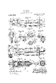
- Figure 1 is a view in elevation of one form of the device as applied to the front axle of a motor car, said view being taken from the rear looking toward the front;
- Fig. 2 is a view in elevation looking from the front toward the rear of a shock absorber construction embodying my invention and particularly adapted for application with the rear axle of a car;
- Fig. 3 is a partial plan view on the line 33 of Fig. 1;
- Fig. 4 a vertical section on the line 44 of Fig. 1, showing the mode of mounting the operating lever;
- Fig. 5 a detail vertical section on the line 55 of Fig. 1 through the support for the dash pot which forms the main element of the shock absorber;
- FIG. 6 is a plan view of one end of the mechanism shown in F i 2;
- Fig. 7 is a vertical section on the line %7 of Fig. 2;
- Fig. 8 is a section on the line 8 of Fig. 2 and
- Fig. 9 is a horizontal and longitudinal section through one of the dash pot cylinders, the construction of which is common to all the cylinders shown in both cylinders 1 and 2;
- Fig. 10 is a section on the line 1010 of Fig. 9.
- 1 is the main spring member consisting, as is usual, of a series of superposed leaf springs and 2 is the front axle.
- the ends of the lowest spring leaf are turned over to form eyes 3 and through these eyes are inserted pins 4 of clevises 5.
- the upper pin 6 of each of these clevises is pivoted in a yoke arm 7, at the inner end of the latter.
- This yoke arm is pivoted at 8 at the upper end of a perch 9 which rises from a strut or bolt 10 carried by the axle.
- the arm 7 has a lateral extension 11 from which extends an integral operating lever arm 12 which is curved slightly outwardly and then directed in-* wardly and downwardly toward the center of the car and is pivoted at its lower end at 13 to the end of a piston rod 14.
- the piston rod 14 extends within a dash pot cylinder 15 and carries at its inner end a piston 16.
- the dash pot cylinder is adapted to contain oil and the piston is movable against the resistance afforded thereby.
- a spiral spring 17 which also aflords a cushioning and shock resisting member is mounted in the cylinder and surrounds the piston rod bearing at one end against the piston and at the other end against the cap 18 secured on the end of the cylinder.
- a stufi'- ing box 19 mounted in the same end of the cylinder and through which the piston rod passes serves to prevent the escape of oil.
- the spring 17 is of light, flexible construction so as to be readily yieldable to slight movements of the piston and therefore responsive to slight shocks or jars imparted to the axle structure.
- the piston of the dash pot is provided with several apertures 20 through which oil the car, illustrated in Figs. 2,
- the dash pot cylinder at its inner end has a threaded cap 23 which carries a collar 24 which surrounds the central portion of a bolt 25.
- the ends of this bolt are threaded and provided with nuts 26.
- An angle iron 27 is mounted on this bolt and one arm; thereof is connected to a rod 28.
- the rod 28 serves to join the ends of. the two cylinders which thus pull against one another.
- the bolt 25 is continued beyond the angle iron and connected pivotally to the upper part of a clamp 29, one for each dash pot which clamps are mounted on the front axle.
- the operation of the front shock absorber is as follows Upon a shock imparted to the axle structure the arm 7 will be tilted downward, rocking the arm 12 upwardly on the pivot 8 and thus pulling the piston rod 14 outwardly against the pressure of the spiral spring 17. Owing to the short arm between the leaf springs or other part to be cushioned and the greater length of the arm 12, the range of movement of the axle vibrations will be greatly multiplied and consequently slight shocks will be readily transmitted to the spiral spring and taken up thereby.
- This spring is light and flexible and therefore sensitive in responding to the shocks. The oil will escape freely through the apertures 22 in this movement against the spring and hence the shock absorbing action due to the upward movement of the axle structure will be readily responsive and quick in action.
- This dash pot is connected by a bolt construction 39 to a clip 40 in a manner similar to that described with respect to the front shock absorber.
- the two dash pots are connected by a rod 41 which in the form shown in Fig. 2 is bent slightly upward at the center to accommodate it to the differential casing.
- the lever arm is curved in the'opposite direction from that indicated in Fig. 1, the operation is the same as described with reference to the construction of such figure.
- the cushioning means and themultiplying lever may be connected to other parts of the car for the purpose of cushioning the riding shocks between the axle and the parts supported thereby.
- a shock absorber for motor cars having a cushioning device located between the axle structure and a structure supported thereby, said cushioning device including rebound-checking means and being carried by a support which is independent of said supported structure and means mounted on the axle structure and operatively connect ing the cushioning means and said supported part for multiplying the range of movement of the axle vibrations, and a member between said connecting means and part and pivotally connected thereto.
- a shock absorber for motor cars in combination with an axle structure of the car and the car structure sup orted by the axle structure, a ushioning evice including rebound checking means, a lever fulcrumed on the axle structure and having one end connected with said supported structure and the other end'with the cushioning means, said lever having its arms so arranged as to multiply the range of vibrations transmitted from said axle structure to the cushioning means, and a clevis pivoted to said supported said supported structure t e same.
- shock absorbing controlling means for motor vehicles comprising a liquid-containing dash pot fixed on the axle and having a piston, and a piston rod, the latter being pivotally connected to the main springs, and a stufling box at one end of the dash pot, and means whereby the piston is retarded by the liquid only on the rebound act-ion and as the piston moves away from the stufling box.
- a shock absorbing cushioning device including rebound checking means, a lever fulcrumed on the axle and a link joining one end of said lever to the end of said set of springs, the lever being pivotally connected to said device, said lever having that arm between the fulcrum and said device longer than its other arm.
- a clevis pivoted to the end of said set, a lever pivoted on the motor car axle, and to said clevis, and a cushioning device including rebound checking means pivoted to one end of said lever.
- a lever fulcrumed on the axle of said car and movable in a vertical plane a dash-pot, said lever being pivotally connected to one end of said set of said springs and to the piston of said dash pot.
- a lever fulcrunied on the axle of the car and operable in a vertical plane a clevis pivoted to the end of said set of springs, a pivotal connection between said clevis and lever, and a dash pot, said lever having a short arm between said clevis and the fulcrum and a longer 'arm between the dash-pot piston and fulcrum.
- cushioning means for the supported structure comprising a dash pot containing a body of liquid, a piston movable in said dash pot and having an opening therethrough, a spring pressing against one side of said piston and a freely movable valve member adapted to close said opening when the piston is moved in one direction and means mounted on the axle connecting said supporting structure and said piston.
- a structure supported by said axle structure a dash-pot near each end of said axle structure, means at one end of each cylinder of the dash pots connected to the piston of said dash pot and connected to said supported structure, means mounted on the axle structure to which the opposite end of said cylinder is pivotally connected and a rod connecting the ends of said cylinders.
- a structure to be supported there by, opposite cushioning dash pots means mounted on said axle structure connecting the pistons of said dash pots With said supported structure, a clip for each dash pot cylinder mounted on the axle structure. a bolt secured to and extending laterally from said clip. an angle iron on the inner end of said cylinder pivotally connected to said bolt and a rod connecting the angle irons of the opposed cylinders.
Landscapes
- Engineering & Computer Science (AREA)
- Mechanical Engineering (AREA)
- Vehicle Body Suspensions (AREA)
Description
C. D. JENNEY SHOCK ABSORBER. APPLICATION FILED JULY 12. I915.
Jan. 21, 1913).
SHEET 1 C l-Henna t2 H AL t nu lwi tme/aoqo C. D. JENNEY.
SHOCK ABSORBER.
1,291,908. Patented Jan. 21,1919.
2 SHEETS-SHEET Z- ami Muses CHARLES D. JENNEY, OF INDIANAPOLIS, INDIANA.
SHOCK-ABSORBER.
Specification of Letters Patent.
Patented Jan. 21, 1919.
Application filed July 12, 1915. Serial No. 39,366.
To all whom it may concern:
Be it known that I, CHARLES D. J ENNEY, a citizen of the United States, residing at Indianapolis, Marion county, and State of Indiana, have invented and discovered certain new and useful Improvements in Shock- Absorbers, of which the following is a specification. I
My invention relates to shock absorbers for motor cars and its object is to provide a device of this class capable of utilizing a very flexible spring so that the absorber will be responsive to slight shocks and jars and also adapted to provide a rebound cushioning medium of greater resistance than the spring, to provide means whereby the motions transmitted to the axle and the main leaf springs of the motor car or other part to be cushioned, will be multiplied in range of movement in" transmission to the shock absorber, to thereby greatly increase the responsive action of the absorber, to provide a construction capable of attachment to the ordinary supporting clevis for the leaf springs, thus avoiding any additional fastening means passing through the leaf springs that would tend to cause the same to bind or buckle in their movement and to provide a construction in which the rebound from the downward movement of the leaf springs or other part connected to the cushioning means is checked and rendered gradual and easy; to provide means whereby an excessive pressure against the stuffing box of the dash pot employed as the cushioning means is avoided in the rebound checking movement, and to provide a con struction which is capable of being readily mounted upon motor cars without substantial change in the construction of the latter.
With these ends in view my invention is embodied in preferable form in the device hereinafter described and illustrated in the accompanying drawings.
In these drawings, Figure 1 is a view in elevation of one form of the device as applied to the front axle of a motor car, said view being taken from the rear looking toward the front; Fig. 2 is a view in elevation looking from the front toward the rear of a shock absorber construction embodying my invention and particularly adapted for application with the rear axle of a car; Fig. 3 is a partial plan view on the line 33 of Fig. 1; Fig. 4 a vertical section on the line 44 of Fig. 1, showing the mode of mounting the operating lever; Fig. 5, a detail vertical section on the line 55 of Fig. 1 through the support for the dash pot which forms the main element of the shock absorber; Fig. 6 is a plan view of one end of the mechanism shown in F i 2; Fig. 7 is a vertical section on the line %7 of Fig. 2; Fig. 8 is a section on the line 8 of Fig. 2 and Fig. 9 is a horizontal and longitudinal section through one of the dash pot cylinders, the construction of which is common to all the cylinders shown in both cylinders 1 and 2; Fig. 10 is a section on the line 1010 of Fig. 9.
Referring to the drawings and first to the shock absorber that is adapted to be ap plied to the front axle of the car as shown in Figs. 1 to 5 inclusive, 1 is the main spring member consisting, as is usual, of a series of superposed leaf springs and 2 is the front axle. As is usual the ends of the lowest spring leaf are turned over to form eyes 3 and through these eyes are inserted pins 4 of clevises 5. The upper pin 6 of each of these clevises is pivoted in a yoke arm 7, at the inner end of the latter. This yoke arm is pivoted at 8 at the upper end of a perch 9 which rises from a strut or bolt 10 carried by the axle. The arm 7 has a lateral extension 11 from which extends an integral operating lever arm 12 which is curved slightly outwardly and then directed in-* wardly and downwardly toward the center of the car and is pivoted at its lower end at 13 to the end of a piston rod 14. The piston rod 14 extends within a dash pot cylinder 15 and carries at its inner end a piston 16. The dash pot cylinder is adapted to contain oil and the piston is movable against the resistance afforded thereby. A spiral spring 17 which also aflords a cushioning and shock resisting member is mounted in the cylinder and surrounds the piston rod bearing at one end against the piston and at the other end against the cap 18 secured on the end of the cylinder. A stufi'- ing box 19 mounted in the same end of the cylinder and through which the piston rod passes serves to prevent the escape of oil. The spring 17 is of light, flexible construction so as to be readily yieldable to slight movements of the piston and therefore responsive to slight shocks or jars imparted to the axle structure.
The piston of the dash pot is provided with several apertures 20 through which oil the car, illustrated in Figs. 2,
is adapted to pass and in the inward rebound checking or snubbing movement of the piston, these apertures are adapted to be closed by a sliding valve disk 21 mounted on the piston rod, whereby the piston Wlll be forced against the oil contained in the dash pot and the latter will be forced gradu-- ally past the piston through the narrow space between the flange 22 thereof and the wall of the cylinder. Owing to the fact that in this rebound checking movement of the piston, the latter moves toward the solid end of the cylinder, excessive pressure on the stufiing box is avoided.
In the movement of the piston in the opposite direction the pressure of the contained oil will carry the valve away from the openings, permitting the oil to escape'to the opposite side of the piston, without offering appreciable resistance to the movement of the piston.
The dash pot cylinder at its inner end has a threaded cap 23 which carries a collar 24 which surrounds the central portion of a bolt 25. The ends of this bolt are threaded and provided with nuts 26. An angle iron 27 is mounted on this bolt and one arm; thereof is connected to a rod 28. The rod 28 serves to join the ends of. the two cylinders which thus pull against one another. The bolt 25 is continued beyond the angle iron and connected pivotally to the upper part of a clamp 29, one for each dash pot which clamps are mounted on the front axle.
The operation of the front shock absorber is as follows Upon a shock imparted to the axle structure the arm 7 will be tilted downward, rocking the arm 12 upwardly on the pivot 8 and thus pulling the piston rod 14 outwardly against the pressure of the spiral spring 17. Owing to the short arm between the leaf springs or other part to be cushioned and the greater length of the arm 12, the range of movement of the axle vibrations will be greatly multiplied and consequently slight shocks will be readily transmitted to the spiral spring and taken up thereby. This spring is light and flexible and therefore sensitive in responding to the shocks. The oil will escape freely through the apertures 22 in this movement against the spring and hence the shock absorbing action due to the upward movement of the axle structure will be readily responsive and quick in action. The return movement will be slow and gradual owing to the pressure of the disk valve 21 against the oil in front of the piston. As the piston moves inwardly in this return movement the oil will be permitted to escape only very slowly and outer flange of the piston, the apertures 20 being closed by the valve.
In the construction for the rear axle of 6, 7, and 8, the
gradually past the 1 operating mechanism is shown as mounted somewhat differentl for the purpose of accommodating it tot e different construction of the rear axle herein illustrated.
In this arrangement 30 are perches mounted upon the brake casings 31 on the rear axle 32 and which perches have arms at their upper ends extending slightly upwardly. These arms are adapted to be embraced by the yoke 33 of a curved lever arm 34. This lever arm 34 has a depending lug 35 fulcrumed at 36 on-the upper pin of a clevis 37, the lower pin 38 of which engages the eye at the end of the leaf springs. The inner and lower end of the operatin lever arm 34 is pivoted to the outer end of a piston rod 36 of a dash pot, the construction of which is the same as that described with reference to the device illustrated in Figs. 1, 3 and 9. This dash pot is connected by a bolt construction 39 to a clip 40 in a manner similar to that described with respect to the front shock absorber. The two dash pots are connected by a rod 41 which in the form shown in Fig. 2 is bent slightly upward at the center to accommodate it to the differential casing. In this form of the device although the lever arm is curved in the'opposite direction from that indicated in Fig. 1, the operation is the same as described with reference to the construction of such figure.
It is evident that in place of being connected to the leaf springs, the cushioning means and themultiplying lever may be connected to other parts of the car for the purpose of cushioning the riding shocks between the axle and the parts supported thereby.
Having thus described my invention, what claim is:
1. A shock absorber for motor cars having a cushioning device located between the axle structure and a structure supported thereby, said cushioning device including rebound-checking means and being carried by a support which is independent of said supported structure and means mounted on the axle structure and operatively connect ing the cushioning means and said supported part for multiplying the range of movement of the axle vibrations, and a member between said connecting means and part and pivotally connected thereto.
In a shock absorber for motor cars, in combination with an axle structure of the car and the car structure sup orted by the axle structure, a ushioning evice including rebound checking means, a lever fulcrumed on the axle structure and having one end connected with said supported structure and the other end'with the cushioning means, said lever having its arms so arranged as to multiply the range of vibrations transmitted from said axle structure to the cushioning means, and a clevis pivoted to said supported said supported structure t e same.
3. In combination with the axle and main springs, shock absorbing controlling means for motor vehicles comprising a liquid-containing dash pot fixed on the axle and having a piston, and a piston rod, the latter being pivotally connected to the main springs, and a stufling box at one end of the dash pot, and means whereby the piston is retarded by the liquid only on the rebound act-ion and as the piston moves away from the stufling box.
4. In combination with a set of leaf springs for a motor'car, a shock absorbing cushioning device including rebound checking means, a lever fulcrumed on the axle and a link joining one end of said lever to the end of said set of springs, the lever being pivotally connected to said device, said lever having that arm between the fulcrum and said device longer than its other arm.
5. In combination with a set of leaf springs of a motor car, a clevis pivoted to the end of said set, a lever pivoted on the motor car axle, and to said clevis, and a cushioning device including rebound checking means pivoted to one end of said lever.
6. In combination with a set of leaf springs of a motor car, a lever fulcrumed on the axle of said car and movable in a vertical plane, a dash-pot, said lever being pivotally connected to one end of said set of said springs and to the piston of said dash pot.
In combination with a set of leaf springs of a motor car, a lever fulcrunied on the axle of the car and operable in a vertical plane, a clevis pivoted to the end of said set of springs, a pivotal connection between said clevis and lever, and a dash pot, said lever having a short arm between said clevis and the fulcrum and a longer 'arm between the dash-pot piston and fulcrum.
and to said lever and connecting Copies 8. In a shock absorber for motor cars, in combination with an axle structure and a structure to be supported thereby, cushioning means for the supported structure comprising a dash pot containing a body of liquid, a piston movable in said dash pot and having an opening therethrough, a spring pressing against one side of said piston and a freely movable valve member adapted to close said opening when the piston is moved in one direction and means mounted on the axle connecting said supporting structure and said piston.
In combination with a motor car axle structure, a structure supported by said axle structure, a dash-pot near each end of said axle structure, means at one end of each cylinder of the dash pots connected to the piston of said dash pot and connected to said supported structure, means mounted on the axle structure to which the opposite end of said cylinder is pivotally connected and a rod connecting the ends of said cylinders.
In combination with a motor car axle structure, a structure to be supported there by, opposite cushioning dash pots, means mounted on said axle structure connecting the pistons of said dash pots With said supported structure, a clip for each dash pot cylinder mounted on the axle structure. a bolt secured to and extending laterally from said clip. an angle iron on the inner end of said cylinder pivotally connected to said bolt and a rod connecting the angle irons of the opposed cylinders.
In .witness whereof, I have hereunto set my hand and seal at Indianapolis, Indiana, this 10th day of July, A. D. nineteen hundred and fifteen.
CHARLES D. JENNEY. [L.S.]
Witnesses:
H. P. DOOLITTLE,
A. C. RICE.
of this patent may be obtained for five cents each, by addressing the Commissioner of Patents,
Washington, I). C.
Priority Applications (1)
| Application Number | Priority Date | Filing Date | Title |
|---|---|---|---|
| US3936615A US1291908A (en) | 1915-07-12 | 1915-07-12 | Shock-absorber. |
Applications Claiming Priority (1)
| Application Number | Priority Date | Filing Date | Title |
|---|---|---|---|
| US3936615A US1291908A (en) | 1915-07-12 | 1915-07-12 | Shock-absorber. |
Publications (1)
| Publication Number | Publication Date |
|---|---|
| US1291908A true US1291908A (en) | 1919-01-21 |
Family
ID=3359466
Family Applications (1)
| Application Number | Title | Priority Date | Filing Date |
|---|---|---|---|
| US3936615A Expired - Lifetime US1291908A (en) | 1915-07-12 | 1915-07-12 | Shock-absorber. |
Country Status (1)
| Country | Link |
|---|---|
| US (1) | US1291908A (en) |
Cited By (1)
| Publication number | Priority date | Publication date | Assignee | Title |
|---|---|---|---|---|
| WO2010077355A1 (en) | 2009-01-05 | 2010-07-08 | Boston Scientific Scimed, Inc. | Synthetic composite structures |
-
1915
- 1915-07-12 US US3936615A patent/US1291908A/en not_active Expired - Lifetime
Cited By (1)
| Publication number | Priority date | Publication date | Assignee | Title |
|---|---|---|---|---|
| WO2010077355A1 (en) | 2009-01-05 | 2010-07-08 | Boston Scientific Scimed, Inc. | Synthetic composite structures |
Similar Documents
| Publication | Publication Date | Title |
|---|---|---|
| US2226406A (en) | Vehicle wheel mounting | |
| US1291908A (en) | Shock-absorber. | |
| US9663182B2 (en) | Front fork | |
| US1519451A (en) | Shock absorber | |
| US1470931A (en) | Shock absorber | |
| US2259827A (en) | Control shackle for leaf springs | |
| US1319937A (en) | Shock-absorber | |
| US2104245A (en) | Vehicle spring suspension | |
| US1205432A (en) | Shock-absorber. | |
| US1434017A (en) | Shock absorber for automobiles | |
| US1319086A (en) | jacques | |
| US1486763A (en) | Suspension device for automobiles or other vehicles | |
| US1179209A (en) | Combined shock-absorber and brace. | |
| US1217970A (en) | Vehicle-spring. | |
| US1001343A (en) | Shock-absorber. | |
| US1474964A (en) | Shock absorber | |
| US1347138A (en) | Shock-absorber | |
| US918429A (en) | Shock-absorbing device. | |
| US1201604A (en) | Equalizer for vehicle-springs. | |
| US1797875A (en) | Shock absorber | |
| US1504012A (en) | Shock absorber | |
| US1561493A (en) | Shock absorber | |
| US2007173A (en) | Spring suspension | |
| US1328641A (en) | Lilbukst howaed van bkiggle | |
| US1267395A (en) | Shock-absorber. |