US1288198A - Pumping-jack. - Google Patents
Pumping-jack. Download PDFInfo
- Publication number
- US1288198A US1288198A US23192518A US23192518A US1288198A US 1288198 A US1288198 A US 1288198A US 23192518 A US23192518 A US 23192518A US 23192518 A US23192518 A US 23192518A US 1288198 A US1288198 A US 1288198A
- Authority
- US
- United States
- Prior art keywords
- shafts
- frame
- cams
- pumping
- pump rod
- Prior art date
- Legal status (The legal status is an assumption and is not a legal conclusion. Google has not performed a legal analysis and makes no representation as to the accuracy of the status listed.)
- Expired - Lifetime
Links
Images
Classifications
-
- F—MECHANICAL ENGINEERING; LIGHTING; HEATING; WEAPONS; BLASTING
- F16—ENGINEERING ELEMENTS AND UNITS; GENERAL MEASURES FOR PRODUCING AND MAINTAINING EFFECTIVE FUNCTIONING OF MACHINES OR INSTALLATIONS; THERMAL INSULATION IN GENERAL
- F16H—GEARING
- F16H25/00—Gearings comprising primarily only cams, cam-followers and screw-and-nut mechanisms
- F16H25/08—Gearings comprising primarily only cams, cam-followers and screw-and-nut mechanisms for interconverting rotary motion and reciprocating motion
- F16H25/14—Gearings comprising primarily only cams, cam-followers and screw-and-nut mechanisms for interconverting rotary motion and reciprocating motion with reciprocation perpendicular to the axis of rotation
-
- Y—GENERAL TAGGING OF NEW TECHNOLOGICAL DEVELOPMENTS; GENERAL TAGGING OF CROSS-SECTIONAL TECHNOLOGIES SPANNING OVER SEVERAL SECTIONS OF THE IPC; TECHNICAL SUBJECTS COVERED BY FORMER USPC CROSS-REFERENCE ART COLLECTIONS [XRACs] AND DIGESTS
- Y10—TECHNICAL SUBJECTS COVERED BY FORMER USPC
- Y10T—TECHNICAL SUBJECTS COVERED BY FORMER US CLASSIFICATION
- Y10T74/00—Machine element or mechanism
- Y10T74/18—Mechanical movements
- Y10T74/18056—Rotary to or from reciprocating or oscillating
- Y10T74/18296—Cam and slide
Definitions
- the present invention relates to improvements in pumping jacks capable of being operated either manually or from a suitable source of power.
- My object has been to provide a simple construction comprising rotary driving instrumentalities embodying cam elements so arranged as to impart reciprocatory motion to a pump operating element, said construction affording a very smooth action and eliminating the sudden or jerky actuation of the pump operating element as is usually the case in conventional types of pumping jacks.
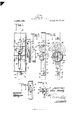
- Figure l is a front elevation of a piunping jack constructed in accordance! ywith my invention.
- Fig. 2 is a vertical sectional view on the line 2&2 of Fig. l.
- Fig. 3 is a side elevation
- Figs. l and 5 are sectional views on the lines 4 4 and 5-5 respectively of Fig. l.
- l indicates a frame which in the present instance is rectangular in shape and has at its base a socket or sleeve 2 carrying a set screw 3 by means of which the frame with its mechanism support-ed thereby may be mounted upon a well casing, pipe or the like indicated at 4.
- the usual pump rod 5 shown in dotted lines is designed to be actuated by the mechanism now to be described.
- Said rod is connected to one end of what I term for the purposes of this description a connecting member 6.
- the upper end of the last-named member is provided with a cross-head or pin 7 preferably having anti-friction rollers 8 thereon.
- the head projects laterally into slots 9 of brackets l0, there being one of such brackets secured to the inner side of each side member of the frame 1.
- brackets l0 Also mounted in the frames and in spaced relation to each other are Specification of Letters Patent.
- each of the shafts ll, ll carries -a relatively large gear 14 and a pinion l5 arranged intermediate the two gears and meshing therewith provides for the rotation of the shafts ll, ll and cams mounted upon the same.
- the pinion l5 is carried by a short shaft 16 journaled in one side of the frame l and a suitable bracket la, said shaft having mounted thereon a fly-wheel 17 and a further pinion 1S operable by the drive gear 19.
- the last-mentioned gear is suitably actuated either by a source of power or manually through the instrumentality of the clutch pulley 20, the details of the construction of which are not herein given inasmuch as they form the subject mattter of a separate application.
- the device is simply constructed and is designed to take the place of the ordinary pumpin respect to the well casing or the pumping jack may be otherwise operatively connected so as to actuate the pump rod in the manner hereinbefore described.
- a pumping j ack of the class described consisting of a. unitary structure comprising a suitable frame, adapted to be disposed in coactingA relation to a pump rod, shafts mounted in said frame in spaced relation to each other7 a Wiper cam mounted upon each shaft, a pump rod connector having its end portion arranged intermediate the cams for impingement thereby as the said cams are operated, guide means for said connector, gear elements for actuating said shafts, and means for driving said gear elements.
- a pumping jack of the class described comprising a frame having attachinglmeans at its base portion, a guide bracket secured to each side of said frame and projecting in- Wardly thereof, cam shafts journaled in said frame7 volutecams adjustably secured to said shafts, a pump rod connector arranged to move vertically between the brackets aforesaid and having a cross pin at one end slidab'ly engaging the brackets to guide the connecten a relatively large gear mounted upon each of the shafts, and a driving pinion arranged intermediate the said gears for actuating the same and driving the cams in the same direction, and means for actuating said gear elements.
- a pump jack attachment comprising a suitable frame having attaching means at its base, upper and lower cam shafts journaled in said frame, a pump rod connector slotted to receive one of said shafts for guiding purposes and having a cross pin at its upper end arranged between the shafts, cams on said shafts adapted to engage the pin for actuating the pump rod in opposite directions, and guide means on said frame with which the pin co-acts to sustain the connector in proper position during reciprocation.
Landscapes
- Engineering & Computer Science (AREA)
- General Engineering & Computer Science (AREA)
- Mechanical Engineering (AREA)
- Reciprocating Pumps (AREA)
Description
Patented DLC 17,1918
,nf/ LW m;
l 6j -L' Q mijl/170i? Zw jawn@ 1j FFIC.
EIJZA RI-IODY, 0F FARMLAND, INDIANA.
PUMPINGr-J'ACK.
Application led May 1, 1918.
To all whom t may concern.'
Be it known that I, ELZA RHoDY, a citizen of the United States, residing at Farmland, in the county of Randolph and State of Indiana, have invented certain new and useful Improvements in Pumping-Jacks, of which the following is a specification.
The present invention relates to improvements in pumping jacks capable of being operated either manually or from a suitable source of power.
My object has been to provide a simple construction comprising rotary driving instrumentalities embodying cam elements so arranged as to impart reciprocatory motion to a pump operating element, said construction affording a very smooth action and eliminating the sudden or jerky actuation of the pump operating element as is usually the case in conventional types of pumping jacks.
With the above and other objects in view, this invention consists in the construction, combination and arrangement of parts, all as hereinafter more fully described, claimed and illustrated in the accompanying drawing, wherein:
Figure l is a front elevation of a piunping jack constructed in accordance! ywith my invention.
Fig. 2 is a vertical sectional view on the line 2&2 of Fig. l.
Fig. 3 is a side elevation; and
Figs. l and 5 are sectional views on the lines 4 4 and 5-5 respectively of Fig. l.
Referring to the drawings and specically describing the device, l indicates a frame which in the present instance is rectangular in shape and has at its base a socket or sleeve 2 carrying a set screw 3 by means of which the frame with its mechanism support-ed thereby may be mounted upon a well casing, pipe or the like indicated at 4. The usual pump rod 5 shown in dotted lines is designed to be actuated by the mechanism now to be described. Said rod is connected to one end of what I term for the purposes of this description a connecting member 6. The upper end of the last-named member is provided with a cross-head or pin 7 preferably having anti-friction rollers 8 thereon. The head projects laterally into slots 9 of brackets l0, there being one of such brackets secured to the inner side of each side member of the frame 1. Also mounted in the frames and in spaced relation to each other are Specification of Letters Patent.
Patented Dec. 17, 1918.
Serial No. 231,925.
upper and lower shafts l1, 1l', the latter eX- tending through slots 6 in the pump rod connector 6, each of said shafts carrying wiper cams or volute cams l2. The cams are secured to their respective shafts by means of set screws 13 and obviously they may be adjusted with respect to their relative positions by means ofthe set screws just mentioned.
At one end each of the shafts ll, ll carries -a relatively large gear 14 and a pinion l5 arranged intermediate the two gears and meshing therewith provides for the rotation of the shafts ll, ll and cams mounted upon the same. The pinion l5 is carried by a short shaft 16 journaled in one side of the frame l and a suitable bracket la, said shaft having mounted thereon a fly-wheel 17 and a further pinion 1S operable by the drive gear 19. The last-mentioned gear is suitably actuated either by a source of power or manually through the instrumentality of the clutch pulley 20, the details of the construction of which are not herein given inasmuch as they form the subject mattter of a separate application.
The operation of the device will be apparent from the foregoing description, it merely suiticing to state that the cams l2 are arranged to impinge the crosshead 7 of the connector 6 for the pump rod so as to positively move the same upwardly and downwardly, guided by the brackets 10, and the coaction of the shafts l1 with the slots 6 the wiping action of the cams being so adjusted that when one is about to leave the cross head the other contacts therewith for actuation of said head in the opposite direction.
The device is simply constructed and is designed to take the place of the ordinary pumpin respect to the well casing or the pumping jack may be otherwise operatively connected so as to actuate the pump rod in the manner hereinbefore described.
Having thus described my invention, what I claim as new is:
l. In pumping apparatus of the class described, the combination with a pump rod, of a frame, a pump rod connector connected at one end with the pump rod and having a cross pin at its other end, guide brackets attachedto the frame and slotted to receive the cross pin, cams mounted in the frame between the brackets and at opposite sides of the cross pin for impinging the latter to impart reciprocatory motion to the connector and pump rod, and means for revolving 'said cams.
2. A pumping j ack of the class described, consisting of a. unitary structure comprising a suitable frame, adapted to be disposed in coactingA relation to a pump rod, shafts mounted in said frame in spaced relation to each other7 a Wiper cam mounted upon each shaft, a pump rod connector having its end portion arranged intermediate the cams for impingement thereby as the said cams are operated, guide means for said connector, gear elements for actuating said shafts, and means for driving said gear elements.
3. A pumping jack of the class described comprising a frame having attachinglmeans at its base portion, a guide bracket secured to each side of said frame and projecting in- Wardly thereof, cam shafts journaled in said frame7 volutecams adjustably secured to said shafts, a pump rod connector arranged to move vertically between the brackets aforesaid and having a cross pin at one end slidab'ly engaging the brackets to guide the connecten a relatively large gear mounted upon each of the shafts, and a driving pinion arranged intermediate the said gears for actuating the same and driving the cams in the same direction, and means for actuating said gear elements.
4. A pump jack attachment comprising a suitable frame having attaching means at its base, upper and lower cam shafts journaled in said frame, a pump rod connector slotted to receive one of said shafts for guiding purposes and having a cross pin at its upper end arranged between the shafts, cams on said shafts adapted to engage the pin for actuating the pump rod in opposite directions, and guide means on said frame with which the pin co-acts to sustain the connector in proper position during reciprocation.
ln testimony whereof I aix my signature.
ELZA RHODY.
Copies of this patent may be obtained for ive cents each, by addressing the Commissioner of Patents. Washington, D. 6.
Priority Applications (1)
| Application Number | Priority Date | Filing Date | Title |
|---|---|---|---|
| US23192518A US1288198A (en) | 1918-05-01 | 1918-05-01 | Pumping-jack. |
Applications Claiming Priority (1)
| Application Number | Priority Date | Filing Date | Title |
|---|---|---|---|
| US23192518A US1288198A (en) | 1918-05-01 | 1918-05-01 | Pumping-jack. |
Publications (1)
| Publication Number | Publication Date |
|---|---|
| US1288198A true US1288198A (en) | 1918-12-17 |
Family
ID=3355765
Family Applications (1)
| Application Number | Title | Priority Date | Filing Date |
|---|---|---|---|
| US23192518A Expired - Lifetime US1288198A (en) | 1918-05-01 | 1918-05-01 | Pumping-jack. |
Country Status (1)
| Country | Link |
|---|---|
| US (1) | US1288198A (en) |
Cited By (1)
| Publication number | Priority date | Publication date | Assignee | Title |
|---|---|---|---|---|
| US4413436A (en) * | 1982-06-01 | 1983-11-08 | Ward Michael L | Aquarium with simulated stream flow |
-
1918
- 1918-05-01 US US23192518A patent/US1288198A/en not_active Expired - Lifetime
Cited By (1)
| Publication number | Priority date | Publication date | Assignee | Title |
|---|---|---|---|---|
| US4413436A (en) * | 1982-06-01 | 1983-11-08 | Ward Michael L | Aquarium with simulated stream flow |
Similar Documents
| Publication | Publication Date | Title |
|---|---|---|
| US634194A (en) | Gearing for pumping-jacks. | |
| US1288198A (en) | Pumping-jack. | |
| US1053871A (en) | Mechanical movement. | |
| US1611914A (en) | Pump jack | |
| US2465033A (en) | Pump jack gearing | |
| US2084612A (en) | Portable electric generator | |
| US1163535A (en) | Pump. | |
| US847229A (en) | Pumping-jack. | |
| US1075956A (en) | Pumping attachment. | |
| US1598553A (en) | Mechanical movement | |
| US276799A (en) | James m | |
| US2812722A (en) | Power drive for reciprocating well pumps | |
| US1547467A (en) | Gearing | |
| US723447A (en) | Transom-lifter. | |
| US1414936A (en) | Pump jack | |
| US1449785A (en) | Pumping jack | |
| US1943139A (en) | Power head for a pump | |
| US1548037A (en) | Milking machine | |
| US1711806A (en) | Pump jack | |
| US789709A (en) | Pump-operating mechanism. | |
| US1272322A (en) | Current-motor. | |
| US427130A (en) | Feed-pump | |
| US817639A (en) | Pump-operating mechanism. | |
| US449848A (en) | Dental engine | |
| US978669A (en) | Driving mechanism for pumps. |