US1280098A - Locomotive. - Google Patents
Locomotive. Download PDFInfo
- Publication number
- US1280098A US1280098A US84076014A US1914840760A US1280098A US 1280098 A US1280098 A US 1280098A US 84076014 A US84076014 A US 84076014A US 1914840760 A US1914840760 A US 1914840760A US 1280098 A US1280098 A US 1280098A
- Authority
- US
- United States
- Prior art keywords
- side frames
- frames
- armatures
- frame
- locomotive
- Prior art date
- Legal status (The legal status is an assumption and is not a legal conclusion. Google has not performed a legal analysis and makes no representation as to the accuracy of the status listed.)
- Expired - Lifetime
Links
Images
Classifications
-
- A—HUMAN NECESSITIES
- A63—SPORTS; GAMES; AMUSEMENTS
- A63H—TOYS, e.g. TOPS, DOLLS, HOOPS OR BUILDING BLOCKS
- A63H19/00—Model railways
- A63H19/02—Locomotives; Motor coaches
- A63H19/10—Locomotives; Motor coaches electrically driven
Definitions
- the object of my inven- ,tion is to provide a, locomotive running gear embodying a plurality of twin motors as-' side frames in such manner that the several armatures are symmetrically. dISPOSBd' about the armatures are mechanically connected.
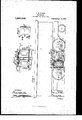
- Figure 1 is a view, partiallyin section and partially in elevation, of a; locomotive constructed: in i accordance with my invention;
- Fig. 2 is a i 1 oeuatershaitell ge ing si e.
- plan view, partially in :1 is partially, nv end .elevation,, ,iof-1 one of vthe,
- the side frames 3 and" 4 are of like struction, and each is provided with pedestal openings to receive the driving axles 5 and 6, in the usual manner, a pedestal openin 16 for receiving the countershaft 11, an a plurality of openings 17 in which bearing housings 18 are disposed. The located symmetrically, 1n
- openings 17 are Specification ofL'et t r's Patent.
- the drivingzunits 9 and 10 are; alQoflike construction, and each comprises a field magnet frame 20 having a pluralityof main polar projections 21, and commutating polar projections 22, and a plurality of armatures 23 that'are verticallydisposed, one above therother, in magnetic relation to the ma n polar projections 21, in such manner that a single magnetic circuit serves in common for both armatures of the twin motor structure; Inasmuch as my present invention pertains only, in a general we to the specific type: of drivinggunit emp oyed, I
- the field magnet structure 20 extends the full width of the locomotive, intermediate the side frames3 and 4;, and its opposite ends are providedwith side 1ugs24 and substantially horizontal end projecting lugs 25.
- the field magnet structure 22 is supported uponits end projecting lugs'25, which rest upon the side frames 3 and 4, and is rigidly secured to said side frames by bolts 26 which cooperate with the side lugs 24:.
- the field magnet structure 22 constitutesa permanent cross-tie of the locomotive frame and lends exceptional strength and rigidity thereto, while permitting ofmaterial econom es-1n space, i v y
- the motorarmatures 23 are examples of the motorarmatures 23.
- a vehicle the combination with a lurality of side frames, of a pair of twin meters supported in sid-byside relation by said side frames, each comprising a plural- 1ty of armatures disposed in vertical relation and a single field-magnet structure serving said armatures in common, a counters'haft intermediate said twin motors, and gearing for mechanically associating said armatures with said countershaft.
- the combination with a plurality of side frames having correspondin ly located openings therein, of a unitary field magnet frame directly mounted on, and serving as a cross-tie for, the side frames, and a lurality of armatur'e's mounted in said field-magnet frame, said ar In-atures being adapted for a longitudinal removal through said side-frame openings.
- a fieldmagnet structure extending the full width of the vehicle between the side-frames, said field magnet structure mounted on, and serving as a cross-tie for, the side frames, of a lin-alit of annatures disposed within saifield-magnet structure, and bearing housings remwably positioned in said side ⁇ Tame openings and adapted to support said 'armatnresandto be secured to one of "said side frames, the armatnies beingremovable through the sideframe e enings.
Landscapes
- Connection Of Motors, Electrical Generators, Mechanical Devices, And The Like (AREA)
Description
N. w. STORER. LOCOMOIIVE. APPLICATION FILED IAY'ZL ISH.
v e Patented Sept. 24,191a
INVENTOR ATTORN EY run (mam:- M2151"; m. ruamu mm. mammzmu, a. c.
UNITED g -ns narnnr OFFICE.
NonmANw; mass; or rrrrssurien, rnN'NsirLvA ra, ASSIGNOR TO WESTINGHOUSE am se e tcomrniigl n 'conronA'rro or PENNSYLVANIA.
LOCOMOTIfVE;
To all whom it may ccmcerm.
Be itknown thatI, NORMAN Strokes,
i a citizen of the United States, and-a resi- ,1
dent of Pittsburgh in the'oounty of ;Alle-- vented anew and useful Improvement'in gheny and Stateof Pennsylvania, have in- 1 Locomotives, of which the following is a I specification.
sembled in side-by-side relation between the 1 van intermediatecountershaft to which all of frames to constitute permanent cross-ties,
and the armatures ofwhioh are carried in bearing housings which are detachably secured to the side frames.
In another aspect, the object of my inven- ,tion is to provide a, locomotive running gear embodying a plurality of twin motors as-' side frames in such manner that the several armatures are symmetrically. dISPOSBd' about the armatures are mechanically connected.
In the accompanying drawing, Figure 1 is a view, partiallyin section and partially in elevation, of a; locomotive constructed: in i accordance with my invention; Fig. 2, is a i 1 oeuatershaitell ge ing si e.
plan view, partially in :1 is partially, nv end .elevation,, ,iof-1 one of vthe,
section, of a portion of the running gear shown in "Fig.1; and
EVIGW, partiallyinsection and,
driving units mounted in position upon the, side;frames. i I ,F Refe 'ing "to the drawing, the locomotive shown com rises a cab 1 andarunnin gear 2 which em odies aplurality of, side 'ames 3 and 4, driving axles 5;.aandfi, driving g Y i I pedestal 'bpening ---,sfl1 (l wheels 7 and 8, twin motors 9 and 10, a
The side frames 3 and" 4 are of like struction, and each is provided with pedestal openings to receive the driving axles 5 and 6, in the usual manner, a pedestal openin 16 for receiving the countershaft 11, an a plurality of openings 17 in which bearing housings 18 are disposed. The located symmetrically, 1n
openings 17 are Specification ofL'et t r's Patent.
1 Application filed May 25, 1914 Serial No. 840.760;
Patented Sept.]24', 1)11 8.
vertical pairs, on each'side of the pedestal opening 16 and are of sufiicient; diameter to permlt theremoval of the motor 'armatures,
as .willibe hereinafter set forth.
The drivingzunits 9 and 10 are; alQoflike construction, and each comprises a field magnet frame 20 having a pluralityof main polar projections 21, and commutating polar projections 22, and a plurality of armatures 23 that'are verticallydisposed, one above therother, in magnetic relation to the ma n polar projections 21, in such manner that a single magnetic circuit serves in common for both armatures of the twin motor structure; Inasmuch as my present invention pertains only, in a general we to the specific type: of drivinggunit emp oyed, I
shall not attempt to describe the structure thereof infurther detail. a
, The field magnet structure 20 extends the full width of the locomotive, intermediate the side frames3 and 4;, and its opposite ends are providedwith side 1ugs24 and substantially horizontal end projecting lugs 25. The field magnet structure 22 is supported uponits end projecting lugs'25, which rest upon the side frames 3 and 4, and is rigidly secured to said side frames by bolts 26 which cooperate with the side lugs 24:. Thus, the field magnet structure 22constitutesa permanent cross-tie of the locomotive frame and lends exceptional strength and rigidity thereto, while permitting ofmaterial econom es-1n space, i v y The motorarmatures 23. are carried upon shafts 28, whichare jpl maled in the bvean inghous-ings 18, said bearing housings being disposed ,within the side frame open ngs v 17 an" d a hab y sl'e'c e i the s d frame 3 holts 191., The openings ,l 7 arje; of diameter to permit ;the removal or y y icien ev au s i fyv h l m re: a ammfl t m hltbss d tir es hen d sire Thet e imsrsl a' t 16 in a In anner one end thereof is provi c with a "en which meshes, in common, with a p urality name- 6mi h that 5 "old" a lli elilaimd well-known linkage or driving connections, which it is deemed unnecessary to describe.
Obviously, many modifications may be effooted in the structural etails and arra emeiitada' location of parts, without departing from the spirit and scope of m ;-inyention and I desire that only such limitations sh all be imposed as are indicated in the appended-claims.
I claim as my invention:
1. In a vehicle, the combination with a plurality of-si'd'e frames, of afield-magnet structure located between said side frames, said field-magnet structure being remevably supported on, and serving as a cross-tie betwen, ye side' frames, and an annature carried 3 said side frames and removable through one of said side frames.
2. In a vehicle, the cembin'atien with a plurality of side frames, of a field magnet structure interposed between Said Side frames and having integral lugs resting upon said side frames, means for rigidly "sccuring said side frames to said structure,
' and an armature carried by said side frames and adapted to be longitudinally removed assets-mugs.
3;" In a=vehic1e, the combination with a plurality of side frames having correspondingly located o enings therein, of bearin housings dispesed therein, as armature mounted in said bearin housings, a fieldin "net frame urrounding said armature an extending the full Width of said vehicle between the side frames, said fieldmagnet frame being reniovahly mounted on, and serving as a cross-tie between, the side frames.
4. In a vehicle, the combination with a pluralit of side frames, of a plurality of m tor mines disposed between said "side frames, said moter'rrames being reniovably situated on, and triving as erassties between, said'side flames-"and a plurality of armatures mounted in each 'ofsaid 'rnotor sates andiridividna lly itintvamt through in the side frames,
v 55. in a vehigilefthe "cmiibiimti on' with a ii may of sid -frames, era plurality of .6!
;ejfliejld-iiiagxfet frame and of a? jfiture s 'disposed' are above a it a1 stuatastteeaniea by said means for mechanically associating all of said armatures with said countershaft.
6. In a vehicle, the combination with a lurality of side frames, of a pair of twin meters supported in sid-byside relation by said side frames, each comprising a plural- 1ty of armatures disposed in vertical relation and a single field-magnet structure serving said armatures in common, a counters'haft intermediate said twin motors, and gearing for mechanically associating said armatures with said countershaft.
7. In a vehicle, the combination with a pair of driving axles and a plurality of side frames supported thereon,- o pair of twin motors adjacently disposed between said axles and supported by said side frames, said twin motors being severally provided with field-magnet frames, a countershaft carried by said side frames between said pair of twin motors and, means for trans."- mitting the driving effort of said twin Inotors to said countershaft and said driving axles.
8. In a vehicle, the combination with a plurality of side frames having correspondin ly located openings therein, of a unitary field magnet frame directly mounted on, and serving as a cross-tie for, the side frames, and a lurality of armatur'e's mounted in said field-magnet frame, said ar In-atures being adapted for a longitudinal removal through said side-frame openings.
9. In a vehicle, the combination with a plurality of side frames, one of which has relatively large openings therein, a fieldmagnet structure extending the full width of the vehicle between the side-frames, said field magnet structure mounted on, and serving as a cross-tie for, the side frames, of a lin-alit of annatures disposed within saifield-magnet structure, and bearing housings remwably positioned in said side {Tame openings and adapted to support said 'armatnresandto be secured to one of "said side frames, the armatnies beingremovable through the sideframe e enings.
In testimon whereof I have hereunto subscribed my name this %1st day of May, 191* NORMAN W. srioiisis.
Wilmw "jf:
manne we
Priority Applications (1)
| Application Number | Priority Date | Filing Date | Title |
|---|---|---|---|
| US84076014A US1280098A (en) | 1914-05-25 | 1914-05-25 | Locomotive. |
Applications Claiming Priority (1)
| Application Number | Priority Date | Filing Date | Title |
|---|---|---|---|
| US84076014A US1280098A (en) | 1914-05-25 | 1914-05-25 | Locomotive. |
Publications (1)
| Publication Number | Publication Date |
|---|---|
| US1280098A true US1280098A (en) | 1918-09-24 |
Family
ID=3347693
Family Applications (1)
| Application Number | Title | Priority Date | Filing Date |
|---|---|---|---|
| US84076014A Expired - Lifetime US1280098A (en) | 1914-05-25 | 1914-05-25 | Locomotive. |
Country Status (1)
| Country | Link |
|---|---|
| US (1) | US1280098A (en) |
-
1914
- 1914-05-25 US US84076014A patent/US1280098A/en not_active Expired - Lifetime
Similar Documents
| Publication | Publication Date | Title |
|---|---|---|
| US1280098A (en) | Locomotive. | |
| US11084506B2 (en) | Articulated railway vehicle, with an improved modularity | |
| DE3140167A1 (en) | DOUBLE AXLE LENGTH DRIVE FOR AN ELECTRIC RAIL DRIVE VEHICLE | |
| US1466262A (en) | Integral cab-frame structure | |
| US508633A (en) | Electric-railway motor | |
| USRE14661E (en) | Locomotive | |
| US808717A (en) | Electric locomotive. | |
| USRE13777E (en) | Joseph le conte davis | |
| US1608697A (en) | Electric motor frame | |
| US1014825A (en) | Electric locomotive. | |
| US538345A (en) | Dynamo-electric machine or electric motor | |
| US1256212A (en) | Dynamo-electric machine. | |
| US1783269A (en) | Direct-drive electric railway truck | |
| US554365A (en) | Electric motor | |
| US1660815A (en) | Pole cable terminal | |
| US449709A (en) | short | |
| US1310049A (en) | Electric locomotive or cab | |
| US1198080A (en) | Dynamo-electric machine. | |
| US608137A (en) | Alexander siemens | |
| US1902504A (en) | Truck | |
| US913666A (en) | Dynamo-electric machine. | |
| USRE12543E (en) | Electric motor | |
| US538104A (en) | Electric motor for railway-cars | |
| US1557051A (en) | Railway motor | |
| US823969A (en) | Electric locomotive. |