US1255152A - Electric socket. - Google Patents
Electric socket. Download PDFInfo
- Publication number
- US1255152A US1255152A US16045617A US16045617A US1255152A US 1255152 A US1255152 A US 1255152A US 16045617 A US16045617 A US 16045617A US 16045617 A US16045617 A US 16045617A US 1255152 A US1255152 A US 1255152A
- Authority
- US
- United States
- Prior art keywords
- screw
- candle
- socket
- block
- base
- Prior art date
- Legal status (The legal status is an assumption and is not a legal conclusion. Google has not performed a legal analysis and makes no representation as to the accuracy of the status listed.)
- Expired - Lifetime
Links
Images
Classifications
-
- F—MECHANICAL ENGINEERING; LIGHTING; HEATING; WEAPONS; BLASTING
- F21—LIGHTING
- F21S—NON-PORTABLE LIGHTING DEVICES; SYSTEMS THEREOF; VEHICLE LIGHTING DEVICES SPECIALLY ADAPTED FOR VEHICLE EXTERIORS
- F21S6/00—Lighting devices intended to be free-standing
- F21S6/001—Lighting devices intended to be free-standing candle-shaped
Definitions
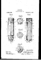
- M V invention relu-tes to electric lamp sockets and Ijmrtieularly to exlension sockel's for candle fittings, the object of my inminimi boing to provide e sin'lple. incxpensive and rugged Structure for this pun- [iosv possessing the novel features hereinv afleiset forth or shown in lne accompany ing drawings in Whiel m Figure 1 is n side elevation of a. socket in which my invention is embodied in one form;
- Figs. 2, 3 und 4 are sections respectively on the lines --Q, 3W-3 ⁇ and 94, Fig. 1;
- Fig. 5 is an inverted plan View thereof.
- the present fitting com rises an. elongated candle-like block of insu ation 10 grooved on its opposite sides at 11 and 12 to receive longitudinally ex tending screw rods v13 and 14.
- boss 15 is formed-thereby providing ashoulder 16 against which the base flan e of the screw shell 17 is seated.
- a charme 18 formed in the boss 1.5 receives the base 19 of the center Contact 20, The extended ortion of the base 19 over-lies a filler bloc' of insulation. 21 bridging the groove 11 and extending between opposite margins of the base flange 16 of the screw shell which is ont awry at this point.
- the block 10 is shouldered at 22 into a slightly reduced area QB'terminatin in a conical boss 24, the base of which is sightly offset to afford a shoulder 25. Seated against the latter is the base fla-nge QG of the screw shell 27 which surrounds the uren Qof the candle tube lll, A hay 28 let into the conical boss 24 receives the base Q9 of the center Contact 30 which overlies the boss '124 :md is provided with el. pair of inwardly extending wings 31 taking inlo shallow Walls 32 formed in the outer end o'ftlie boss 24. A piece of. insulation is interposed. lie'wwn. the bese 52S) of the center contini. mid the screw ehe-ll buse flange oi whirl; not point.
- An extension socket comprising an elongated candle-.like block of insulating mw terial grooved on its opposite sides, center and shell contacts at each end thereof and screw bolts lying ⁇ in said grooves and respectively engaging the terminal pairs to not only electrically connect the coordinated contacts, but to mechanically secure'the same in position at opposite ends of the insulating block.
- An extension socket comprising an elongated candle-like block of insulating Ineterialgrooved on its opposite sides,center and shell contacts et each end thereof and screw elongated candle-like block of insulating inalying in said grooves within the area of said screw shells and serving to electrically oonnect the terminal pairs and secure the same in position on the block.
- An extension socket comprising an teriol, grooved on its opposite sides, shell and center contacts arrnngedon said block at opposite ends thereof, said screw shell contacts having inwardly projecting base lianges and the center contacts having bases extending outwardly t0 the area of said hase Ilanges for the screw shells, but insulated therefrom, together witli bolts lying in said grooves and passing through said base ianges of the screw shells and the bases of the center contacte;4 and serving to electrically connect said terminal pairs and rnechanieally secure them; on said insulating block, substantially as described.
Landscapes
- Engineering & Computer Science (AREA)
- General Engineering & Computer Science (AREA)
- Connecting Device With Holders (AREA)
Description
F. P. GATES.
ELECTRIC SOCKET.y APPUCATION FILED APB. 7. 19H.
1 Patented Feb. 5, 1918.
-sind UNITED STATES PATENT oEmoE.
FREDERIC I. GATES, 0F HARTFORD, CONNECTICUT, ASSIGNOR T0 THE .ARROW ELECTRIC COMPANY, OF HARTFORD, CONNECTICUT, A CORPORATIN O'F CONNECTCUT.
4ELECTRIC SOCKET,
Spccllciztion of Letters Patent.
Patented Feb. 5, 1918.,
Application led April 7, 1917. Serial No. 180,558.
To all 'whom t may conoern:
Be it known that l, FREDERIC l. GATES, a citizen of the United Stat-es of America, and residing in Hartford, in the county of Hertford und Stale of Connecticut, have invented i certain new and useful improven nient in Electric Sockets, of which the .following is e specification.
M V invention relu-tes to electric lamp sockets and Ijmrtieularly to exlension sockel's for candle fittings, the object of my inminimi boing to provide e sin'lple. incxpensive and rugged Structure for this pun- [iosv possessing the novel features hereinv afleiset forth or shown in lne accompany ing drawings in Whiel m Figure 1 is n side elevation of a. socket in which my invention is embodied in one form;
Figs. 2, 3 und 4 are sections respectively on the lines --Q, 3W-3 `and 94, Fig. 1;
Fig. 5 is an inverted plan View thereof.
The growing popularity of candle-like fittinge has milde it deeimble to 'provide :i device by which -an ordinary lamp socket may be Converted into n fitting of candle type. Various' devices Jfor this purpose have been provided lont have proven objectionable for one reason or another` The present device provides n. candle extension .fitting which while inexpensive ro manufacture, is rugged and serviceable and Well adapted lfor the service required.
In the form here shown the present fitting com rises an. elongated candle-like block of insu ation 10 grooved on its opposite sides at 11 and 12 to receive longitudinally ex tending screw rods v13 and 14. At the outer end ofthe block e raised non-eircnler boss 15 is formed-thereby providing ashoulder 16 against which the base flan e of the screw shell 17 is seated. A charme 18 formed in the boss 1.5 receives the base 19 of the center Contact 20, The extended ortion of the base 19 over-lies a filler bloc' of insulation. 21 bridging the groove 11 and extending between opposite margins of the base flange 16 of the screw shell which is ont awry at this point. Y
At its opposite or inner end the block 10 is shouldered at 22 into a slightly reduced area QB'terminatin in a conical boss 24, the base of which is sightly offset to afford a shoulder 25. Seated against the latter is the base fla-nge QG of the screw shell 27 which surrounds the uren Qof the candle tube lll, A hay 28 let into the conical boss 24 receives the base Q9 of the center Contact 30 which overlies the boss '124 :md is provided with el. pair of inwardly extending wings 31 taking inlo shallow Walls 32 formed in the outer end o'ftlie boss 24. A piece of. insulation is interposed. lie'wwn. the bese 52S) of the center contini. mid the screw ehe-ll buse flange oi whirl; not point.
It iis olorion.-` rind center Contact while the Screw: x-ilnll 20 form zx socket element el. the oppoeite of the candle body 10. These plug and socket contacts are not only .electrically een nectedbut also held upon lthe eandle body 10 by the two screw bolts 13 and 14, The '.15 screw bolt .1,3 through the bese 19 of the eenter'eontaet S50 and etende downward into the groove 11 within the screw shell i?? :ind through' the bnee iange thereof into er gagement with e henry Washer "which is topped to receive it zuid forms in efieet during nul'. The screw bolt 14.V i'verlies el bose flange llfi'of the screw Eboli i? p down Within the groove i f 2 lakes into the tapped bus contact 3G. li will be noteri 1'2 extends into the reduced nre-n candle body 1U so flint. ne noir. spaced from the screw shell and is i dunger'of Contact therewithh 1t is readily seen that the device may be economicallyY manufactured since the onepiece insulating body is easily molded from porcelain. while the metal parts closely ap proximate standard types and may be reni ily struck to-shape.
Various modifications and details of eonstruction, contour and arrengementof parte will readily oecnr to those skilled in the mit wit-hout departing from what I claim as my invention. Thus longitudinal, perforations' of the body 1U may he substituted for the grooves 11 and 12 and' in the l.following claims I use the word grooves in ai sense broad enough to inclucleany suitable. aperture for the reception of the 'screw holte and '14 and the .insulation of the letter.v
1. An extension socket comprising an elongated candle-.like block of insulating mw terial grooved on its opposite sides, center and shell contacts at each end thereof and screw bolts lying` in said grooves and respectively engaging the terminal pairs to not only electrically connect the coordinated contacts, but to mechanically secure'the same in position at opposite ends of the insulating block.
2. An extension socket comprising an elongated candle-like block of insulating Ineterialgrooved on its opposite sides,center and shell contacts et each end thereof and screw elongated candle-like block of insulating inalying in said grooves within the area of said screw shells and serving to electrically oonnect the terminal pairs and secure the same in position on the block.
4. An extension socket comprising an teriol, grooved on its opposite sides, shell and center contacts arrnngedon said block at opposite ends thereof, said screw shell contacts having inwardly projecting base lianges and the center contacts having bases extending outwardly t0 the area of said hase Ilanges for the screw shells, but insulated therefrom, together witli bolts lying in said grooves and passing through said base ianges of the screw shells and the bases of the center contacte;4 and serving to electrically connect said terminal pairs and rnechanieally secure them; on said insulating block, substantially as described.
In. testimony 'whereof l have signed my name to this speeiiication. Y
FREDERIC P, GATES.y
Priority Applications (1)
| Application Number | Priority Date | Filing Date | Title |
|---|---|---|---|
| US16045617A US1255152A (en) | 1917-04-07 | 1917-04-07 | Electric socket. |
Applications Claiming Priority (1)
| Application Number | Priority Date | Filing Date | Title |
|---|---|---|---|
| US16045617A US1255152A (en) | 1917-04-07 | 1917-04-07 | Electric socket. |
Publications (1)
| Publication Number | Publication Date |
|---|---|
| US1255152A true US1255152A (en) | 1918-02-05 |
Family
ID=3322847
Family Applications (1)
| Application Number | Title | Priority Date | Filing Date |
|---|---|---|---|
| US16045617A Expired - Lifetime US1255152A (en) | 1917-04-07 | 1917-04-07 | Electric socket. |
Country Status (1)
| Country | Link |
|---|---|
| US (1) | US1255152A (en) |
-
1917
- 1917-04-07 US US16045617A patent/US1255152A/en not_active Expired - Lifetime
Similar Documents
| Publication | Publication Date | Title |
|---|---|---|
| US2181145A (en) | Swivel electric connection | |
| US1255152A (en) | Electric socket. | |
| US1907422A (en) | Electric socket | |
| WO2019007143A1 (en) | Double-loop elastic conductive mechanism | |
| US1894606A (en) | Flash light | |
| US2522012A (en) | Flashlight | |
| US1336431A (en) | Combination socket and adapter | |
| US1479520A (en) | Electric switch | |
| US753276A (en) | A cobporation of illi | |
| US1045733A (en) | Electric switch. | |
| US1505228A (en) | Electric switch and lamp socket | |
| US1114157A (en) | Spark-plug. | |
| US2012771A (en) | Universal electric connection | |
| US1295588A (en) | Lamp-socket switch. | |
| US1229185A (en) | Incandescent-electric-lamp plug. | |
| US748599A (en) | Incandescent-electric-lamp socket | |
| US457072A (en) | Incandescent-lamp socket | |
| US551357A (en) | Incandescent electric lamp | |
| US807671A (en) | Combined socket and plug for incandescent lamps. | |
| US321933A (en) | Henri piepeb | |
| US1458636A (en) | Spark plug | |
| US1681425A (en) | Electric socket | |
| US1578684A (en) | Fuse plug | |
| US735188A (en) | Lamp-socket. | |
| US1790000A (en) | Illuminated train-order hoop |