US1251663A - Filing appliance. - Google Patents
Filing appliance. Download PDFInfo
- Publication number
- US1251663A US1251663A US85283514A US1914852835A US1251663A US 1251663 A US1251663 A US 1251663A US 85283514 A US85283514 A US 85283514A US 1914852835 A US1914852835 A US 1914852835A US 1251663 A US1251663 A US 1251663A
- Authority
- US
- United States
- Prior art keywords
- section
- cover
- holders
- case
- hinged
- Prior art date
- Legal status (The legal status is an assumption and is not a legal conclusion. Google has not performed a legal analysis and makes no representation as to the accuracy of the status listed.)
- Expired - Lifetime
Links
Images

Classifications
-
- A—HUMAN NECESSITIES
- A47—FURNITURE; DOMESTIC ARTICLES OR APPLIANCES; COFFEE MILLS; SPICE MILLS; SUCTION CLEANERS IN GENERAL
- A47B—TABLES; DESKS; OFFICE FURNITURE; CABINETS; DRAWERS; GENERAL DETAILS OF FURNITURE
- A47B63/00—Cabinets, racks or shelf units, specially adapted for storing books, documents, forms, or the like
Definitions
- M M 33W may vToall 4whomz't may concern.
- the Vinvention relates to ,a filing -appliin which; ak pluralityof bill-holders are op, eratively mounted inea fire-proof.casecoin-l prising. a rectangularzbase section ⁇ and a,
- connection between the cover andbase sec-p tions and external Lcoiinterbalancing K.
- means for .the cover section are provided fonswing- .Y ing ⁇ and-shifting the-.cover section upon the base section, and in which a series ofhinged bill holders and-an indexi 1frame are pivoted to the rear rim of thelcover ⁇ section.
- hinged holders l have :their hinged ends depending 'froma pivotaliconnection vwith the rear Irirn'of the coversection, with meansj forfsupporting and guiding theffree,ends- 'o'f the-. 'holderswupward and forward-from within the basesection; over andupon the forward rniftliereof, andmeans bearing in the base section forelevating andgsustain-f ing ithe ⁇ fhinged ends of Lthe holders.
- counterbalancing .d means for the cover section thereof, and elevating and sustaining means for. the pendent hinged ends of the holders therein; and to coordinate thev ⁇ operation .of these meanskso that the counterbalance will. not come into pla7 until the cover section. has been swung part way downward vfrom upright position, and -SO that the renergy of the'liolder elevating andsustaining means will bezadded 4to the cover counterbalancing meaiisnas the -cover is swung toward and into itsreclined ,similar lcover rsection ,adapted to benswungclosed position.
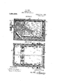
- Figure l is a side elevation section .of the ease showing ⁇ the .cover section closedd'ownward upon thebase section thereof and the holders inclosed. therein;
- Fig. ⁇ 2 a plan section of :the: caseon line A.f2- 2, Fig-.1, showing the holders ⁇ and ,o,ther parts therein, as in Fig. l; f
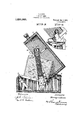
- Fig. 3 a side elevation section ,of vthe case showing the cover Ysection''swungupivard part way upon the rear end ofthe base sectionv and the bill holders carrieltlpartviiay upwardV andforward toward operative position; I .K Y.
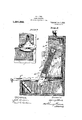
- Fig. ,4 Va fragmentary sidev .eleiratiom partly in sectiomshowing one guidingV hinge.: connection, with thel cover sectionl positioned ,as inFig. V3; n K i Fig. 5,a similar section ofthe. case,. show ing'the cover section swung into ',uprightpof sitioiiupon wthe rear endof thebase and the; billholders carried fully -upward for- )vard into vreclined'y operative position v. 6, asimilar section showingpall the bill holders rotatedinto upright position; and d Fig. 7, a side elevation partly in section, of one guiding hinge connection showing the cover section positioned as in Figs. 5 and 6.
- the case is composed of the substantially rectangular bottom or base section 1 and the top or cover section 2, which are operatively connected together by means of the guiding hinge brackets 3, one bracket being located on each side of the rear end portion of the base section; by means of which the cover section can be swung and shifted upon the base section to aline either the top or rear end of the cover section with the rear end of the base section.
- the series of bill holders 4 and 4 are hinged together at the lower rear ends, and the pivot 5 between two adjoining intermediate holders 4a and 4b are mounted in the bearing 6 secured on the rear end of the cover section; so that the holders above this bearing may be referred to as the upper division of the series, and the holders below this bearing may be referred to as the lower division of the series.
- the lower forward bill holder 4a of the series is pivoted at 7 to the rear end of the ⁇ frame 8, which may carry an index 8a for the bill holders, or may form a table for writing or other use, or may be considered merely as a tray for supporting the superposed holders at certain times.
- Rollers 9 are journaled on each side of the forward end of the frame 8, and tracks 10 are secured on each inner side of the side walls of the base section of the case; on which tracks the rollers 9 are adapted to ride as the frame 8 is carried downward and rearward into the base section by its rear end pivotal connection with the lower holder of the series, when the cover section is closed downward upon the base section, as shown in Fig. 1.
- rollers 11 are preferably journaled to the upper end of each track 10, upon which rollers the side edge portion of the frame at their lower end and having the stop pins 16 on their upper free ends, the main sliding head 17 having apertures 18 therein for each of the guide rods 15 and 15a and the minorsliding head 19 having apertures 20 therein for the inner guide rods 15a.
- the outer and inner coiled compression springs 2O and 21 are located around the outer and inner guide rods 15 and 15a, the outer springs extending between the bearing head 14 and the main sliding head' 17, and the inner springs extending between the bearing head 14 and the minor sliding head 19.
- the lower end of the bearing plate 13 is pivoted at 22 to the lower end of the pendent link 23, which has its upper end pivoted by the post 24 to the adjacent side wall of the base section of the case, which pivot post extends inward beyond the inner side of the link 23 of the bearing plate 13, to serve as a pivotal abutment or stop for the rear edge thereof.
- the main sliding head 17 is pivoted at 17a to the adjacent side wall of the cover sectionof the case adjacent to the forward edge thereof; and the hinged end of the lower holder 4a is pivoted at 25 to the lower end of the swinging link 26, which link has its upper end pivoted at 27 to the inner side of the minor sliding head 19.
- the parts and the strength of the springs are so proportioned and arranged that when the cover section is swung and shifted into upright position upon the rear end of the base section of the case, with the holders car ried forward into reclined operative position, as shown in Fig. 5, the stop pins 16 on the upper ends of the guide rods 15 and 1.5'aL will bear upon the upper side of the main slide head 17 which is pivoted at 17a to the cover section of the case, the weight of the pendent parts being supplemented by the energy of the several springs.
- the bill holders 4, 4t and 4b comprising the upper division ofthe series, may be rotated upon their hinged ends into upright position, either singly or collectively, in which upright position the upper rear holder of this division is sustained and guided by the abutment rollers 28 provided one in each side of the ⁇ cover section, and theforward holder 42L thereof is supported by the pivotal bearing 6 on the rear rim of the cover section, as shown by broken lines in Fig. 5; so that the rotated holders of this division will be maintained in upright position by the action of gravity in the manner well known in ⁇ this art.
- Vbill holders 4', 4a and 4b comprisng thev lower' :divisiomof the-fseries, ⁇ arefi'rotated on their hinged ends into uprightposition, asi
- For closing the:.case,;r.it1i ⁇ sIpreferred to'V 1 rota-tefall the billholdersf'of the'fseries ford'. ⁇
- a filing case including similarbase and cover sections'with-- Yguiding-fhingel ⁇ connec'# tions forsivinging and-shifting the'cover sectionsfupon the basesectionfa plurality of hinged v'holdersmounted in the case having itheir hinged endsdependingA from apivotal clzonnectionvvith the rear" end of'theecover to counterbalance 'theiwight'fofthe covernwwhen the -coverl .section iszi-nf and44 near its section of the case during the inal portion all the compression springs will serve to assist in elevating the cover section during the first portion of its movement into upright position.
- a filing case including similar base and cover sections With guiding hinge connections for swinging and shifting the cover section upon the base section, a plurality of hinged holders mounted in the case having their hinged ends depending'from a pivotal connection with the rear end of the cover upright position for counterbalancing the sameyvhensvvung "downivard'rint' interme- -diate and closed positions, and means for elevating and sustaining the hinged ends of the holders supplementing the cover counterbalance means When the cover section is in and near its closed position.
- a filing case including similar base and cover sections with guiding hinge connections for swinging and shifting the cover sections upon the base section, a plurality of hinged holders mounted in the case having their hinged ends depending from a pivotal connection With the rear end of the cover section, means for supporting and guiding the free ends of the holders upward and forward from Vwithin the base section over the forward rim thereof, means inoperative when the cover section is in and near its upright position for counter-balancing the same when swung downward-into intermediate and closed positions, and means for elevating and sustaining the hinged ends of Vthe holders cordinated with and supplethe forward rim thereof, a frame including a bearing member with a plurality of slide rods extending upward therefrom havingstop pins on their upper ends, a main head Y pivoted to the case cover having sliding engagement with the rods, a minor head in the path of the main head having sliding engagement with certain of the rods, compression springs around the rodsbetween the bearing member and the respective sliding heads, a pendent link pivoted to the
- a filing case including similar base and cover sections with guiding hinge connections for swinging and shifting the cover section upon the base section, a plurality of hinged holders mounted in the case having their hinged ends depending from a pivotal connection with the rear end of the cover section, counterbalance means for the cover section, and means for elevating and sustaining the hinged ends of the holders supplementing the -counterbalance means when the cover section is in and near its closed position.
- khaving base and cover sections hinged together, a plurality of bill holders operatively mounted within the case, and counterbalancing and sustaining means for the cover section and bill holders, the counterbalancing means for the cover section being inoperative when the cover section is in and near its upright position and being operative when swung downward into intermediate or ⁇ closed position.
- a filing case including similar base and cover sections with guiding hinge connections for swinging and shifting the cover sections upon the base section, a plurality of hinged holders mounted in the case, having their hinged ends'depending from a pivotal connectionwith the rear end of the cover section, anindex frame pivoted to the hinged end ofthe lower holder, aroller on the free end of the frame, and means for Vsupporting and guiding the free 'end of the frame upward and forward from within the base section over the forward rim thereof including inclined tracks upon which lthe rollersV of the index frame are adapted to travel.
- a filing case including similarbase and cover sections with guiding hinge connections for swinging and shifting the cover section upon the base section, a plurality of hinged holders mountedin the case, having their hinged ends depending from a pivotal connection with ⁇ the rear end of thecover section, an index frame pivoted to the hinged end ofa lower holder, a roller on the free end of the frame, and means for sup- ⁇ porting and guiding the free end ofthe frameupward and forward from within the base section over the forward rim thereof -including inclined tracks Aupon which the Yrollers of the index frame are adapted to travel;
Description
HJ. HlcK. FILING APPLIANCE.
. APPLICATION FILED JULY 24.1914.
Papented Jan. 1, 1918.
4 SHEE TS-SHEET 4.
Eras, E,
M M 33W may vToall 4whomz't may concern.'
citizen of therUnitedQStates, ,residing atA ance for sales bills and otheigsiinilarpapers,`
Serial No. 843,602, a. lingappliance ofthis scribed and ,-claimed,in which guiding hinge.
*UiviTEDsTATEs PATENT OFFICE.
. .HARRY J.. 1110K. @remmen Q.Hioiessleres TO ,THE MGGASKEY REGMEMQM- .f .Palm @montone-rs1.) 1n. 191e @minimes new, Ad commer@ espino.
. EILING errLieNCE Speciicaton of Letters Patent.
7. PatentedJan.1,1918.
Application filed Jnly 24, 191,4... ,Sera1No. V352,835. v
Be it known. that .1,HARRY ,Ji HioK, a
Alliance, ,in the county ;-of` Stai-l;v andrState.` of Ohio,-haie invented `certain new:gand useful Improvements in Filing Appliances, of which the followingisfaspecification.
.The Vinvention relates to ,a filing -appliin which; ak pluralityof bill-holders are op, eratively mounted inea fire-proof.casecoin-l prising. a rectangularzbase section `and a,
on the.baseseetion to. incase the bill holders when closed, and to formv aback forv the saine when opened.
In a formerfapplicationled J une 8,191@4 type .or characterz has been illustrated, de-
connections: between the cover andbase sec-p tions and external Lcoiinterbalancing K. means for .the cover section are provided fonswing- .Y ing` and-shifting the-.cover section upon the base section, and in whicha series ofhinged bill holders and-an indexi 1frame are pivoted to the rear rim of thelcover` section.
Vln afsubsequent application iiledJ une 12, 1914, Serial No. 844,672, a lilingappliance of this type-and character lifisloeen,illus-A trated-described and claimed, in Iwhich a seriesof hinged holders-have theirliinged ,ends pivoted. intermediate the end holders to the rear rim of the cover section of the case, with supporting` and guiding means for the free endsy of the holders in the basesection .l of the case, and with swinging contracting connections between the-.hinged end .of the lowerholder of the series and thecover sec-` tion of the case for elevating and sustaining. the pendent hinged endsof thelo-weiliolders.I .I
'And in alaterapplicationiled,July' 23, 1911i, Serial No.. 52,600; aV filing appliance of thistype or character has been illustrated, describedV and claimed-,j` in whiclia plurality of. hinged holders lhave :their hinged ends depending 'froma pivotaliconnection vwith the rear Irirn'of the coversection, with meansj forfsupporting and guiding theffree,ends- 'o'f the-. 'holderswupward and forward-from within the basesection; over andupon the forward rniftliereof, andmeans bearing in the base section forelevating andgsustain-f ing ithe` fhinged ends of Lthe holders.
li Theiobject ofzthenpresentiillllilll;isf0.3;
combinewithin the case, counterbalancing .d means for the cover section thereof, and elevating and sustaining means for. the pendent hinged ends of the holders therein; and to coordinate thev `operation .of these meanskso that the counterbalance will. not come into pla7 until the cover section. has been swung part way downward vfrom upright position, and -SO that the renergy of the'liolder elevating andsustaining means will bezadded 4to the cover counterbalancing meaiisnas the -cover is swung toward and into itsreclined ,similar lcover rsection ,adapted to benswungclosed position. 1
This object is attained byasseinbling the @oven `counterbalance springs and .the holder elevating and sustainingVK springs inentensible framesA within' each .side offthe case,
Vby pivot-ally connecting the upp'eieiids of these-.frames with 'the cover section the case, by., providing the lower'. end lofthe frame with a pendentlink conilectionfwith thevbase section of the cased, andby providing a kswinging link connection. .between the uppery ends of the elevating and S.,Uhplorting springs, and the hingedend of the/,lower holder. i f
.A preferred embodiment of the invention, thiisbriefly setforth, iswillustr'ratfeld iii' the accompanying` drawings, .forming,partihereof, in whicli4 p r.Figure l is a side elevation section .of the ease showing `the .cover section closedd'ownward upon thebase section thereof and the holders inclosed. therein;
. Fig.` 2, a plan section of :the: caseon line A.f2- 2, Fig-.1, showing the holders `and ,o,ther parts therein, as in Fig. l; f
Fig. 3, a side elevation section ,of vthe case showing the cover Ysection''swungupivard part way upon the rear end ofthe base sectionv and the bill holders carrieltlpartviiay upwardV andforward toward operative position; I .K Y.
Fig. ,4, Va fragmentary sidev .eleiratiom partly in sectiomshowing one guidingV hinge.: connection, with thel cover sectionl positioned ,as inFig. V3; n K i Fig. 5,a similar section ofthe. case,. show ing'the cover section swung into ',uprightpof sitioiiupon wthe rear endof thebase and the; billholders carried fully -upward for- )vard into vreclined'y operative position v. 6, asimilar section showingpall the bill holders rotatedinto upright position; and d Fig. 7, a side elevation partly in section, of one guiding hinge connection showing the cover section positioned as in Figs. 5 and 6.
Similar numerals refer to similar parts throughout the drawings.
The case is composed of the substantially rectangular bottom or base section 1 and the top or cover section 2, which are operatively connected together by means of the guiding hinge brackets 3, one bracket being located on each side of the rear end portion of the base section; by means of which the cover section can be swung and shifted upon the base section to aline either the top or rear end of the cover section with the rear end of the base section.
The series of bill holders 4 and 4 are hinged together at the lower rear ends, and the pivot 5 between two adjoining intermediate holders 4a and 4b are mounted in the bearing 6 secured on the rear end of the cover section; so that the holders above this bearing may be referred to as the upper division of the series, and the holders below this bearing may be referred to as the lower division of the series.
The lower forward bill holder 4a of the series is pivoted at 7 to the rear end of the `frame 8, which may carry an index 8a for the bill holders, or may form a table for writing or other use, or may be considered merely as a tray for supporting the superposed holders at certain times. Rollers 9 are journaled on each side of the forward end of the frame 8, and tracks 10 are secured on each inner side of the side walls of the base section of the case; on which tracks the rollers 9 are adapted to ride as the frame 8 is carried downward and rearward into the base section by its rear end pivotal connection with the lower holder of the series, when the cover section is closed downward upon the base section, as shown in Fig. 1.
The rollers 11 are preferably journaled to the upper end of each track 10, upon which rollers the side edge portion of the frame at their lower end and having the stop pins 16 on their upper free ends, the main sliding head 17 having apertures 18 therein for each of the guide rods 15 and 15a and the minorsliding head 19 having apertures 20 therein for the inner guide rods 15a.
The outer and inner coiled compression springs 2O and 21 are located around the outer and inner guide rods 15 and 15a, the outer springs extending between the bearing head 14 and the main sliding head' 17, and the inner springs extending between the bearing head 14 and the minor sliding head 19.
The lower end of the bearing plate 13 is pivoted at 22 to the lower end of the pendent link 23, which has its upper end pivoted by the post 24 to the adjacent side wall of the base section of the case, which pivot post extends inward beyond the inner side of the link 23 of the bearing plate 13, to serve as a pivotal abutment or stop for the rear edge thereof. The main sliding head 17 is pivoted at 17a to the adjacent side wall of the cover sectionof the case adjacent to the forward edge thereof; and the hinged end of the lower holder 4a is pivoted at 25 to the lower end of the swinging link 26, which link has its upper end pivoted at 27 to the inner side of the minor sliding head 19.
The parts and the strength of the springs are so proportioned and arranged that when the cover section is swung and shifted into upright position upon the rear end of the base section of the case, with the holders car ried forward into reclined operative position, as shown in Fig. 5, the stop pins 16 on the upper ends of the guide rods 15 and 1.5'aL will bear upon the upper side of the main slide head 17 which is pivoted at 17a to the cover section of the case, the weight of the pendent parts being supplemented by the energy of the several springs. During this movementof the cover section, the lower end of the bearing plate 13 is swung forward by its pivotal connection with the pendent link 23 to carry the link upward nearly into horizontal position; and the swinging link 26 between the hinged end of the lower holder 4a and the niinorslide head 19 draws this head downward, by sliding upon the inner guide rods against the resistance of the inner compression springs 21, to a substantial dis tance below the main slide head 17, all as shown in the same ligure.
In this relation of the parts it is'evident that the bill holders 4, 4t and 4b, comprising the upper division ofthe series, may be rotated upon their hinged ends into upright position, either singly or collectively, in which upright position the upper rear holder of this division is sustained and guided by the abutment rollers 28 provided one in each side of the `cover section, and theforward holder 42L thereof is supported by the pivotal bearing 6 on the rear rim of the cover section, as shown by broken lines in Fig. 5; so that the rotated holders of this division will be maintained in upright position by the action of gravity in the manner well known in `this art.
Furthermore, wheny one or more of the Vbill holders 4', 4a and 4b",- comprisng thev lower' :divisiomof the-fseries, `arefi'rotated on their hinged ends into uprightposition, asi
shown lforall the.iiolders in.Fig.f6, the acl YI tioni'of therinnerzcompressienfsprings 15%.A b'yrthrusting@ upward thexminor slide headi-` `19 and the 'swingingslink Qpivoted* thereto, fservesto elevate' andfsustainathehinged end fof the 'lower'ifriholder 4%', so=that all thevv Iholders-.in ther-lower3division 'of thefseries'r- A.which 1have"beenarotated into'fupright posi--A tion Will-:loe maintained ini such position. Inl.
- e.' this operation Ithe minor head 191 may slide upward into contact'with theimain head 17-v f when all Ltheholders-.ef the lower series arefau. rotated into"1upr1ght i position, -as` shown mr" the same .figure 17 'slides dWiiWard upon the guide rods fa enough to impinge the min'oizhead *19; so;7 that all the compressionspringsWill serve" .i section; means for 1s.upportingfA and l'. guiding thefree ends of theholders -upvvar'di and -orward .-i'romi within the;baseilsectionsover the 'forward rim thereofiincluding inclined trackshavingzfrollers on their; upper@y ends iforf bearing the forward ends of thefholders when eXtendingove-r thefbase rim.
A 'tiling' caseincluding similar base' and cover sections with guiding hinge1 connections' for Vswinging andi'shifti'ng thee-cover section upon the basefsectionyafplurality of hinged holders mounted inthe case? having their hinged ends dependinggifrom a pivotal connection `with the rear end'of th'effcover section, means for 'supporting and Vgui-ding the freeends or' the'holders upward and for- ."For closing the:.case,;r.it1i`sIpreferred to'V 1 rota-tefall the billholdersf'of the'fseries ford'.`
iwardr'luponiltheirshingfed Sends intofr'reclined position, -superposed upon the Lfrazme. 8, asn I -shovvn 'finfj Fig. 'fgflfixvhereupon fifa-li 'forward swinging and rearward shiftinglof Ith'ecover 1f sectiontoclosefitsupon the-base section, will carry theframe '5.8i andf:st1per'posed2iholders- "thereon febodily' downward i and rearwardzl -1 "withinfthe-tw'sections of Ithe ca'se,1'as?shovvnI inkFig. 1. -flffl "During their first .portion'oiithisVmovement it is evident that the lowerfpivoted`A ends ofthe'bearing `plateld and the pendenti link 23 willfstvingtffreelyfdownward'! andl rearward las; shown in' Fig. 3, and itheenergyf la of theirouteur-compression; springs "-Qli Will-kf noti be'fhrou'ght into play Ito: .counterhalancev the "coverfsectionnuntil the! rear@ 'edge' of the? bearing?platev limpinges' theflprotrudingv, s pivot post 24,5;Whereuponina further down- Ward`l .swinging of the'l cover?V sectionl` will 1f if vrotate thetspri'ng-vframe ar'ound kthefpivot pst 24. asla@ulcrurn,` and-"Willf-ailsd slide the iim'ain 'head 'fldoW-nwvard upon tl'ieiiguide` firods, thereby'fcompressing the outer springsf i '15e-betweenthisnhead an'diithe bearinggzhead, .1 whehteounterhal'ancing.fresstance; will be. supplemented by a further compression of-l the inner springs 21a when the main headn iHWardvfromllwithin the loasefsectionl over the @for-Ward* rim. thereof vincluding Y inclined ytracks havingy shoulders on theirloWerfends foI bearing the forward 'ends loff the jholders I"f-When `carried* downward Within the base section.
Y '3u-AA tiling case' including similar" base ,andcover sections'withf guiding-hinge conne'ctions 'for swinging andshifti-ng the cover *ffsection upon the= basel section; aplurality of' hingediholders mountedy in the case having i `their hinged ends# depending from a '.pivotalf connection-With the rear endof the cover section, means forsupportingf and l vtguiding thefree -endsof the holders upward and forwardffrom Within thelbasewsection over the forwardrim thereof, and/means inoperative-When the cover sectionis -i'Ii and near .its uprightv position for counterbalance ingthe samejand the.rearvvard=thrustof the holders when! lsvvung 'downward into tintermediate and V-closedlpositions 4. A filing case including similarbase and cover sections'with-- Yguiding-fhingel` connec'# tions forsivinging and-shifting the'cover sectionsfupon the basesectionfa plurality of hinged v'holdersmounted in the case having itheir hinged endsdependingA from apivotal clzonnectionvvith the rear" end of'theecover to counterbalance 'theiwight'fofthe covernwwhen the -coverl .section iszi-nf and44 near its section of the case during the inal portion all the compression springs will serve to assist in elevating the cover section during the first portion of its movement into upright position.
I claim:
1. A filing case including similar base and cover sections With guiding hinge connections for swinging and shifting the cover section upon the base section, a plurality of hinged holders mounted in the case having their hinged ends depending'from a pivotal connection with the rear end of the cover upright position for counterbalancing the sameyvhensvvung "downivard'rint' interme- -diate and closed positions, and means for elevating and sustaining the hinged ends of the holders supplementing the cover counterbalance means When the cover section is in and near its closed position.
5. A filing case including similar base and cover sections with guiding hinge connections for swinging and shifting the cover sections upon the base section, a plurality of hinged holders mounted in the case having their hinged ends depending from a pivotal connection With the rear end of the cover section, means for supporting and guiding the free ends of the holders upward and forward from Vwithin the base section over the forward rim thereof, means inoperative when the cover section is in and near its upright position for counter-balancing the same when swung downward-into intermediate and closed positions, and means for elevating and sustaining the hinged ends of Vthe holders cordinated with and supplethe forward rim thereof, a frame including a bearing member with a plurality of slide rods extending upward therefrom havingstop pins on their upper ends, a main head Y pivoted to the case cover having sliding engagement with the rods, a minor head in the path of the main head having sliding engagement with certain of the rods, compression springs around the rodsbetween the bearing member and the respective sliding heads, a pendent link pivoted to the base and the bearingv member and having the case pivot extended to form a pivotal abutment for the bearing member, and a swinging link pivotally connected with the minor head and the hinged end of the lower holder.
7 A filing case including similar base and cover sections with guiding hinge connections for swinging and shifting the cover section upon the base section, a plurality of hinged holders mounted in the case having their hinged ends depending from a pivotal connection with the rear end of the cover section, counterbalance means for the cover section, and means for elevating and sustaining the hinged ends of the holders supplementing the -counterbalance means when the cover section is in and near its closed position.
8. A filing applianceincludmg a .case
khaving base and cover sections hinged together, a plurality of bill holders operatively mounted within the case, and counterbalancing and sustaining means for the cover section and bill holders, the counterbalancing means for the cover section being inoperative when the cover section is in and near its upright position and being operative when swung downward into intermediate or `closed position.
9. A filing case including similar base and cover sections with guiding hinge connections for swinging and shifting the cover sections upon the base section, a plurality of hinged holders mounted in the case, having their hinged ends'depending from a pivotal connectionwith the rear end of the cover section, anindex frame pivoted to the hinged end ofthe lower holder, aroller on the free end of the frame, and means for Vsupporting and guiding the free 'end of the frame upward and forward from within the base section over the forward rim thereof including inclined tracks upon which lthe rollersV of the index frame are adapted to travel. i
l0. A filing case including similarbase and cover sections with guiding hinge connections for swinging and shifting the cover section upon the base section, a plurality of hinged holders mountedin the case, having their hinged ends depending from a pivotal connection with` the rear end of thecover section, an index frame pivoted to the hinged end ofa lower holder, a roller on the free end of the frame, and means for sup- `porting and guiding the free end ofthe frameupward and forward from within the base section over the forward rim thereof -including inclined tracks Aupon which the Yrollers of the index frame are adapted to travel; i
p HARRY J. HICK.
Witnesses:
JACOB BACHOFEN, EARL C. CARLSON.
Copies of this patent may be obtained for ve cents eacl'nbyaddressing the Commissioner ofratents,
Washington, D. C. l
Priority Applications (1)
| Application Number | Priority Date | Filing Date | Title |
|---|---|---|---|
| US85283514A US1251663A (en) | 1914-07-24 | 1914-07-24 | Filing appliance. |
Applications Claiming Priority (1)
| Application Number | Priority Date | Filing Date | Title |
|---|---|---|---|
| US85283514A US1251663A (en) | 1914-07-24 | 1914-07-24 | Filing appliance. |
Publications (1)
| Publication Number | Publication Date |
|---|---|
| US1251663A true US1251663A (en) | 1918-01-01 |
Family
ID=3319388
Family Applications (1)
| Application Number | Title | Priority Date | Filing Date |
|---|---|---|---|
| US85283514A Expired - Lifetime US1251663A (en) | 1914-07-24 | 1914-07-24 | Filing appliance. |
Country Status (1)
| Country | Link |
|---|---|
| US (1) | US1251663A (en) |
-
1914
- 1914-07-24 US US85283514A patent/US1251663A/en not_active Expired - Lifetime
Similar Documents
| Publication | Publication Date | Title |
|---|---|---|
| US2769676A (en) | Elevating and lowering device | |
| US1251663A (en) | Filing appliance. | |
| US1402929A (en) | Folding shelf | |
| US742118A (en) | Office-desk. | |
| US1120050A (en) | Bookcase. | |
| US471203A (en) | Child s folding bed | |
| US427217A (en) | Melvin bancroft | |
| US876498A (en) | Folding bed. | |
| US1463289A (en) | Convertible desk | |
| US1565247A (en) | Cabinet desk | |
| US1135215A (en) | Credit-account register. | |
| US1094786A (en) | Cabinet-table. | |
| US2429362A (en) | Combined cabinet and extensible table | |
| US450873A (en) | Combined extension show-table | |
| US1030111A (en) | Cabinet. | |
| US960943A (en) | Wall-bed. | |
| US848258A (en) | Combined desk, table, and book-rest. | |
| US1190894A (en) | Filing appliance. | |
| US1761661A (en) | Filing appliance | |
| US1214681A (en) | Filing appliance. | |
| US1470455A (en) | Chair | |
| US1761704A (en) | Office cabinet | |
| US507401A (en) | Extension-table | |
| US404805A (en) | William a | |
| US442658A (en) | Melvin bancroft |