US1250737A - Shock loading and unloading machine. - Google Patents
Shock loading and unloading machine. Download PDFInfo
- Publication number
- US1250737A US1250737A US17818917A US17818917A US1250737A US 1250737 A US1250737 A US 1250737A US 17818917 A US17818917 A US 17818917A US 17818917 A US17818917 A US 17818917A US 1250737 A US1250737 A US 1250737A
- Authority
- US
- United States
- Prior art keywords
- shaft
- loading
- conveyer
- cylinder
- unloading machine
- Prior art date
- Legal status (The legal status is an assumption and is not a legal conclusion. Google has not performed a legal analysis and makes no representation as to the accuracy of the status listed.)
- Expired - Lifetime
Links
- 230000035939 shock Effects 0.000 title description 8
- 230000003247 decreasing effect Effects 0.000 description 2
- 230000014509 gene expression Effects 0.000 description 1
- 238000004804 winding Methods 0.000 description 1
Images
Classifications
-
- A—HUMAN NECESSITIES
- A01—AGRICULTURE; FORESTRY; ANIMAL HUSBANDRY; HUNTING; TRAPPING; FISHING
- A01D—HARVESTING; MOWING
- A01D57/00—Delivering mechanisms for harvesters or mowers
- A01D57/01—Devices for leading crops to the mowing apparatus
- A01D57/06—Devices for leading crops to the mowing apparatus using endless conveyors
-
- B—PERFORMING OPERATIONS; TRANSPORTING
- B65—CONVEYING; PACKING; STORING; HANDLING THIN OR FILAMENTARY MATERIAL
- B65G—TRANSPORT OR STORAGE DEVICES, e.g. CONVEYORS FOR LOADING OR TIPPING, SHOP CONVEYOR SYSTEMS OR PNEUMATIC TUBE CONVEYORS
- B65G2203/00—Indexing code relating to control or detection of the articles or the load carriers during conveying
- B65G2203/04—Detection means
- B65G2203/042—Sensors
Definitions
- Fig.5 is 'a sectional" view thei'e'of;
- Fig. 6 is an elevation of' tlie'adjns'ting device foftlieloadihg corive' 'er,
- Fig. 7 a longitudinal section-'th'fbu gh the jack sha'ftof the machine'
- Fig. 8 is an enlarged detail of the lower end of the loading conveyer
- Fig. 9 is a fr 'g'ifiefitefyiside""elevation looking at the side'of th'e miichineopposite that shown in Fig.1.
- Means for adjusting the conveyer frame 27 toan inoperative position when not 1n use and to this end use is preferably madeof a transverse shaft 52 rotatably supported at the forward end of the body 13 and operated by a hand wheel 53 to wind and unwind the cables or other flexible elements 53 which pass around the pulleys 54 carried bythe body 13 adjacent the upper end thereof, the ends of said cables being secured to the conveyer frame 27 at 55 and it will thus be seen by winding the cables 53 upon the shaft 52 the frame 27 and its associated parts will be slidingly adjusted upon the worm supported by the shaft 61 rotatable in thebearings 62 carried by the frame 10 of the machine.
- the forward end of the shaft 61 is provided with a gear 63 meshing with a larger gear 64 carried by the shaft 65 journaled transversely of said frame 10 the end of the shaft 65 opposite that carry- Gop ies of this patent may be obtained for k
- a machine of ing the gear 64 being provided with a sprocket 66 around which passes a drive chain 67 which also engages a sprocket 68 carried upon the adjacent end of the jack shaft 23'so that-assaid shaft is rotated the power will be transmitted through the differe'nt parts just described to therear drum 58 thus operating the apron 56.
- the shaft 61 is preferably provided with a clutch69- operable through the medium of a lever 70' pivoted to the frame 10 andarranged adjacent the drivers seat 20.
- a machine of the classdescribed comprising a body, a loadmgconveyer assooiated therewith, a rotatable loading cylinfor varying the speed 'ofirotation of said cylinder whereby to distribute shocks 'into different parts-of said body.
- j the classdescribed comprising a body, a loading conveyer associated therewith, a rotatable loading cylinder at .der at oneend of said conveyer, and means one end of said conveyer, a friction ⁇ diskv shaft, and a friction drive roller adjustable longitudinally .jsaid shaft and-towardand away from the center of said disk tovary the speed of rotation thereof whereby to distribute shocks into different parts of said body.
- a machine of the class describedcomtherewith a rotatable loading cylinder at one end of said conveyer, a friction disk 1 carried by said cylinder, a shaft arranged adjacent thereto, means for driving said shaft, a friction drive roller adjustable longitudinally of said shaft and toward and away from thecenter of said disk to vary the speed of rotation thereof whereby to distribute shocks into different parts of said body, and means supported by said conveyer and connected to said friction roller for adjusting the same.
Landscapes
- Life Sciences & Earth Sciences (AREA)
- Environmental Sciences (AREA)
- Rollers For Roller Conveyors For Transfer (AREA)
Description
A. H. WARTCHOW.
HocK LOADING AND UNLOADING MACHINE.
APPLICATION FILED JULY 2, l9"- Patented D00. 18, 1917.
3 suns-swan 1.
A. H. WARTCHOW.
S'HQCK LOADING AND UNLOADING MACHINE.
APPLICATION FILED JULY 2, 911- Y Patented Dec. 18, 1917.
3 SHEETS-SHEET 2.
APPLICATION FILED JULY 2. 1917.
Patented "Bed-18, 1917'.
m N H p'ositingthe' same-z t different pl'gic es' fin the 'body of the maol1inesothattheflattei fis uniformly loaded as the'opera'tiolfof' 'zithering "the shocks piog'fes'sesthus eliminating. P
' the Iiec eSSitYof additional labor wevem'y distribute shocks in 'the body "as the safne is beingfil ledi 4 i Another] objeet "is to 'pifovide the body of the machinewith at bottomin the fofni" "of an endless-plate or apron connected to? the drive shaft =o'f the maehi ne and" 'co'ntfdljled nd; actuated-get, the'will oft-he opemwr, w
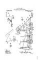
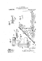
same has 'bee'n'filled The inventive idea involved is 'eapable of receiving "a 'var'ietybf mechanical expressions, one of which; for the urpose of ill-ifstrating the invention, 'is shown in the ztd'ooniy panyin'g-drawing',"wherein z i Figure 1' is anel'ev a tion' looking-Sit one side of them'achine, Fig.2 is'atoppmn View} Fig.8 isa longitildirfzil section,
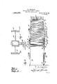
Fig. 4isanen1arge'd deta l. View of" the lozidthe shocksfrom the bottbni-f alftrfthe mechanism for changing-the speedibf the g a theiewith. B
loading cylinder employedin 1 connection With the invention,
Fig.5 is 'a sectional" view thei'e'of; Fig. 6 is an elevation of' tlie'adjns'ting device foftlieloadihg corive' 'er,
Fig. 7 a longitudinal section-'th'fbu gh the jack sha'ftof the machine',
Fig. 8 is an enlarged detail of the lower end of the loading conveyer,
Fig. 9 is a fr 'g'ifiefitefyiside""elevation looking at the side'of th'e miichineopposite that shown in Fig.1.
- r. yAIiBEM H. "WQRT.CHQW,OFFDEERiENG?NGRTH Diskette-1 Specification of I let te r of North Dakotztfheve "inventedceftiih new meme machinwfid if mm a siiocii eAniivex-nisrn m moieiqiii.iifiib iifinii f f L 1, "Ii
m f y a'mag-e whee-tensileether pare of t'heinzi'ehine: i The teeth cai'i'iedfbj at at the eu porft ed ina ydbe or drum 41 operated through the mediumof a shaft 42 having the gear 43 at one end 7 meshing with a gear 44 carried. by. the end of the shaft 36 opposite the sprocket 39. This shaft 42 has adjustable longitudinally thereof a friction drive roller 45 adapted to engage the friction disk 46 carried by the cylinder 41 whereby the- -lat;ter is rotated. It is proposed, in the present invention, to
vary the speed of rotation of the cylinder 41 in order to automatically control the distribution of shocks intothe body 13 from the conveyer 37 so that said body will be uniformly loaded and it will be apparent .that'by increasing the speed of the cylinder 41 the shocks; will be thrown toward the rear end of: the body 13 and by decreasing said speed the shockswill fall nearer the front endflof the machine, the distance from vsaid front end decreasing in proportion to the decrease in the speed of rotation of said cylinder; In order to vary this speed of rotation the friction roller 45 is connected to one end of a rod 47 the other end of which is connected to thenbell crank lever 48 car- ,ried by the adjacent side. of the frame .27, V and pivoted to said bell crank lever is a rod or link 49 -to which is connectedthe operating lever 5 0 pivoted to the side of the frame 27 and working over a rack segment 51. It
.willbe seen from this description thatby adjusting the lever 50 the roller 45 may be adjusted toward and away from the center 1 of. the friction disk 46 and thus increase and decrease the speed thereof. Means are also provided for adjusting the conveyer frame 27 toan inoperative position when not 1n use and to this end use is preferably madeof a transverse shaft 52 rotatably supported at the forward end of the body 13 and operated by a hand wheel 53 to wind and unwind the cables or other flexible elements 53 which pass around the pulleys 54 carried bythe body 13 adjacent the upper end thereof, the ends of said cables being secured to the conveyer frame 27 at 55 and it will thus be seen by winding the cables 53 upon the shaft 52 the frame 27 and its associated parts will be slidingly adjusted upon the worm supported by the shaft 61 rotatable in thebearings 62 carried by the frame 10 of the machine. The forward end of the shaft 61 is provided with a gear 63 meshing with a larger gear 64 carried by the shaft 65 journaled transversely of said frame 10 the end of the shaft 65 opposite that carry- Gop ies of this patent may be obtained for k A machine of ing the gear 64 being provided with a sprocket 66 around which passes a drive chain 67 which also engages a sprocket 68 carried upon the adjacent end of the jack shaft 23'so that-assaid shaft is rotated the power will be transmitted through the differe'nt parts just described to therear drum 58 thus operating the apron 56. When loading the body 13 it is desirable that the apron 56 remain stationary and for this purpose the shaft 61 is preferably provided with a clutch69- operable through the medium of a lever 70' pivoted to the frame 10 andarranged adjacent the drivers seat 20.
flVhat is claimed is 1. A machine of the classdescribed comprisinga body, a loadmgconveyer assooiated therewith, a rotatable loading cylinfor varying the speed 'ofirotation of said cylinder whereby to distribute shocks 'into different parts-of said body.
4 2. A'machine of the class described prising a body, aloading conveyer asso- V.
. ciatedtherewith, a rotatable loading .cylin- 'der at one end ofsaidconveyer, and afric- 'tion drive member engaging said; cylinder .for varying the speed of rotation, thereof wherebyfto distributeshocks into different parts of said body.
j the classdescribed comprising a body, a loading conveyer associated therewith, a rotatable loading cylinder at .der at oneend of said conveyer, and means one end of said conveyer, a friction} diskv shaft, and a friction drive roller adjustable longitudinally .jsaid shaft and-towardand away from the center of said disk tovary the speed of rotation thereof whereby to distribute shocks into different parts of said body.
4. A machine of the class describedcomtherewith, a rotatable loading cylinder at one end of said conveyer, a friction disk 1 carried by said cylinder, a shaft arranged adjacent thereto, means for driving said shaft, a friction drive roller adjustable longitudinally of said shaft and toward and away from thecenter of said disk to vary the speed of rotation thereof whereby to distribute shocks into different parts of said body, and means supported by said conveyer and connected to said friction roller for adjusting the same. 6 r f In testimony whereof, I aflix my signature in the presence of two witnesses.
ALBERT H. WARTOHOW.
WVitn esses v "A, I; ENGEBRETSON,
L. J WARKENTHIEN.
five cents each, by addressing the Coinmissioaeroflatenta, Was-hm 'gton;D.GJ
carried by said cylinder,a shaft arranged ,adjacentthereto, means for driving said prising a body, a loading conveyer associated V
Priority Applications (1)
| Application Number | Priority Date | Filing Date | Title |
|---|---|---|---|
| US17818917A US1250737A (en) | 1917-07-02 | 1917-07-02 | Shock loading and unloading machine. |
Applications Claiming Priority (1)
| Application Number | Priority Date | Filing Date | Title |
|---|---|---|---|
| US17818917A US1250737A (en) | 1917-07-02 | 1917-07-02 | Shock loading and unloading machine. |
Publications (1)
| Publication Number | Publication Date |
|---|---|
| US1250737A true US1250737A (en) | 1917-12-18 |
Family
ID=3318463
Family Applications (1)
| Application Number | Title | Priority Date | Filing Date |
|---|---|---|---|
| US17818917A Expired - Lifetime US1250737A (en) | 1917-07-02 | 1917-07-02 | Shock loading and unloading machine. |
Country Status (1)
| Country | Link |
|---|---|
| US (1) | US1250737A (en) |
Cited By (1)
| Publication number | Priority date | Publication date | Assignee | Title |
|---|---|---|---|---|
| US3195711A (en) * | 1963-07-03 | 1965-07-20 | Deere & Co | Elevator drive and distributor |
-
1917
- 1917-07-02 US US17818917A patent/US1250737A/en not_active Expired - Lifetime
Cited By (1)
| Publication number | Priority date | Publication date | Assignee | Title |
|---|---|---|---|---|
| US3195711A (en) * | 1963-07-03 | 1965-07-20 | Deere & Co | Elevator drive and distributor |
Similar Documents
| Publication | Publication Date | Title |
|---|---|---|
| US1250737A (en) | Shock loading and unloading machine. | |
| US1160777A (en) | Corn husking and harvesting machine. | |
| US2648945A (en) | Portable haystacker | |
| US2492223A (en) | Swather | |
| US1031472A (en) | Corn and cane header. | |
| US1293706A (en) | Floating threshing-machine. | |
| US1273312A (en) | Portable loader and elevator. | |
| US909576A (en) | Manure pulverizer and loader. | |
| US2437629A (en) | Loading machine | |
| US2301241A (en) | Mucking machine | |
| US1855421A (en) | Loading machine | |
| US1386048A (en) | Straw-rack | |
| US1454551A (en) | Header | |
| US1029451A (en) | Corn-sheller. | |
| US1715469A (en) | Loading machine | |
| US599500A (en) | g-ilman | |
| US1372282A (en) | Harvesting-machine | |
| US1075935A (en) | Hay-loader. | |
| US1520165A (en) | Shock loader | |
| US1722547A (en) | Road-preparing machine | |
| US1538139A (en) | Header attachment | |
| US1426212A (en) | Loader | |
| US666804A (en) | Feeder attachment for threshing-machines. | |
| US1295271A (en) | Grain-shocking machine. | |
| US1420716A (en) | Straw spreader for harvester thrashers |