US1248902A - Machine for recording or listing items on cards. - Google Patents
Machine for recording or listing items on cards. Download PDFInfo
- Publication number
- US1248902A US1248902A US78745613A US1913787456A US1248902A US 1248902 A US1248902 A US 1248902A US 78745613 A US78745613 A US 78745613A US 1913787456 A US1913787456 A US 1913787456A US 1248902 A US1248902 A US 1248902A
- Authority
- US
- United States
- Prior art keywords
- card
- cards
- pin
- recording
- machine
- Prior art date
- Legal status (The legal status is an assumption and is not a legal conclusion. Google has not performed a legal analysis and makes no representation as to the accuracy of the status listed.)
- Expired - Lifetime
Links
Images


Classifications
-
- B—PERFORMING OPERATIONS; TRANSPORTING
- B41—PRINTING; LINING MACHINES; TYPEWRITERS; STAMPS
- B41K—STAMPS; STAMPING OR NUMBERING APPARATUS OR DEVICES
- B41K3/00—Apparatus for stamping articles having integral means for supporting the articles to be stamped
- B41K3/005—Cheque stamping machines
Definitions
- Patented D06. 4 1917- 15 SHEETS- -SHEET 7.
- the system of perforations used in most ofthe columns of the card is a simple one, using a separate hole space for each of the nine digits.
- the resent machine is'designed to use only four iiole spaces for thenine digits, some of the digits being represented by combinations-o1 erforations in two or more of the spaces. his secures a much more compact card and machine; or permits the indicating of more.
- the machine is of the key-board type and has an automatic feed for the cards.
- the necessary keys, which setsthe printing and perforating mechanism in correspondmachine may be operated by hand or by a-..
- precautionary devices are not necessary with a motor.
- means are provided for rendering these precautionary devices inoperative so as to permit the change of the machine from hand operation to motor operation.
- Fig. 2 is a plan with a part of the casingremoved and part of the mechanism in hori- Fig. 3 is a longitudinal section approximately on the line H'of Fig. 2.
- Fig. 4 is a longtiudinal section approximately 011 the line 4.4 of Fi 2.
- Fig. 4* is an enlargement o a part of Fig. 4, showing the construction of the punches and immediately related mechanism.
- Fig. 4 is a side elevation of the mechanism for shifting the card vertically, the plane of this figure being approximately on the line-1.” ofFig. 2.
- Fig. 4 is a rear elevation of .a backing plate for the card.
- Fig. 5 is a longitudinal section approxi- Fig. 5 is a detail of Fig. 5, shown separately for greater clearness.
- Fi 6- is a vertical transverse section approximately on the line 6-6 of Fig. 2 omitting certain parts for the sake of clearness.
- Fig. 6 is aside elevation of the mechanism for stopping the movement of the card in its recording position.
- Fig. 6 is a transverse section showing the main shaft and plates carried thereby.
- Figs. 7 and 8 are perspective views of detai s.
- Figs. 9 to 13 inclusive are side elevations of details.
- - Fig. 15 is a. perspective view of a detail.
- Figs. 15' and 15 are diagrams showing the clip in successive positions.
- Figs. 16 and 17 are perspective views of details.
- Figs. 18 to 20 inclusive are front elevations of a card in the successive stages of the operation.
- Fig. 21 is a perspective view of the ma- 5 chine with a cash register attachment applied thereto.
- Fig. 22 is a side elevation, partly in section, of the cash register attachment.
- Fig. 23 is a plan of the same, partly in section.
- Fig. 24 is a horizontal section of the dials, and connections of the cash register attachment.
- Fig. 25 is a perspective view of the machine of Fig. 1 with a listing attachment added thereto.
- Fig. 26 is a side elevation, partly in section of the listing mechanism applied to the printing and punching machine.
- Fig. 27 is a plan of a rear part of Fig. 26.
- Fig. 28 is a detail of the mechanism for feeding the strip on which the list is made.
- the machine has at the rear pockets or guideways for the cards A, one at the left for receiving the blank cards containing printed titles of the different items which are to be recorded thereon, and one at the left for receiving the cards upon which the various numbers and amounts have been printed under the appropriate titles and which have been correspondingly perforated.
- a card is shown also inthe middle position in which the recording operation takes place.
- a key-board On the front portion of the machine is a key-board containing recording keys B from 1 to 9 (zero being recorded when no key is pressed). At the front of the key-board there is located an accumulator C which carries the total of certain numbers recorded on the successive cards. A total button D is arranged adjacent to the key-board which, when pressed, causes the printing of the total and causes the accumulator to return to zero so as to start a new total thereon.
- the main shaft E projects slightly at the right of the casing and may carry a handle F (Fig. 3) which is pulled forward and released for each recording operation. Or the.
- a handle may be removed and the shaft con nected with a motor designed to oscillate the shaft at the proper rate.
- Adjacent to the key-board is a pull-up G which throws out of operation certain controlling devices which are necessary when the machine is operated by hand, but not when it is operated by motor.
- a long button or strip H which is pressed to start the motor after the desired keys for any recording operation have been pressed.
- Fig. 18 shows the card at this stage.
- the foremost card in the pocket J is shifted to the center of the machine in the vertical plane of the recording apparatus and then downward to bring an upper portion thereof in line with the recording devices and the latter are operated to form the upper printed line thereon (the numerals 24 139 and 285) and to form an upper set of perforations corresponding to said numerals.
- the card after receiving this first line of the record is indicated in Fig. 19. It is then lifted and a second line of records applied thereto consisting, for example, of the numerals 16, 27, and 53.40 and the corresponding lower set of perforations as indicated in Fig. 20.
- the system of perforations in four hole spaces to correspond with the numerals is fully described in my previous application No. 666,944, filed December 20, 1911, and others, and need not be further described here. Any system of combinations of either four or more hole spaces may be used.
- the position of the card for the recording of the second line is indicated in dotted lines in Fig. 19.
- the recording devices act always in the same horizontal plane so that by shifting the card downward the first line is recorded and by thereafter shifting it upward the second line is recorded below the first. From the dotted line position of Fig. 19 the card is shifted horizontally to the right and enters the front of the right hand delivery pocket K, forcing back the previous cards therein against a weight or spring or the like; whence the cards may be removed from time to time as desired.
- the pusher P is illustrated in Figs. 2, 5 and 6. It overlaps the foremost card in the pocket J and is. provided on its inner face with a projection Q of approximately the same thickness as a card and adapted, in the retracted position of the pusher, toengag'e the rear edge of the foremost card.
- the pusher is guided at top and bottom upon a pair of transverse rods .R and S and is pivotally connected at its rear with a horizontal arm T on a short vertical shaft U which is oscillated at suitable intervals throu h connections at its lower end hereinafter el scribed. This causes a movement of the pusher sufiicient to slightly advance the foremost card to the right.
- the card is caught by grippers, the upper one of which is indicated in Fig. 15 and comprises an inner jaw V fixed on a short upwardly extending shaft W, and an outer jaw X pivoted on the same shaft and pressed toward the jaw V by means of a. tension spring Y between a pin on the shaft and a tail on the jaw.
- a in Z bears against a projection a on a. ame carrying the shaft W to limit the backward movement of the jaw X.
- the shaft W is carried in a horizontal projecting portion 6 of the frame 0, and the shaft carries at its upper end a lever d which connected through a link 6 with a similar lever f on the upper end of a shaft, 9 which carries the gripper h, j-which pulls the card from the recording position to the discharge pocket.
- a tension spring k Connected to the lever f is a tension spring k which connects it with a hook Z pivoted on the frame 0 at its rear end and having a lug m which in the retracted position shown in Fig. 15 bears against a fixed pin a projecting downward from the top of the easing (see Fig. 6) so as to stretch the spring is.
- the cam g is pivotally suspended at r and pulled backward by the spring 8 connected to anarm of a hook t which is pivotally supported from the top of. the casing by a pivot u and the forward end of which engages a pin '0 on the underside of the cam.
- the bent lever d on the shaft W carries a roller to which,
- the frame 0 carries rollers y which travel on the rod R, .Fig. 6.
- a similar frame 0' is located immediately below the frame, 0 andvconnected thereto by a stiff plate 2 so that the two frames move together, the rollers of the lower frame traveling on the rod S.
- the shaftg which carries the right hand cli h, j is extended downward into .the lower frame.0' (see Fig. 3) where it carries a similar clip,.and the lower clips are connected to each other by arms and links similar to the parts a, d and 7' shown in Fig. 15.
- the lower clips and the upper clips partake simultaneously of the same movements.
- the card in the recording position similarly stopped by striking a stop 3 (Figs. 6 and (3) which is withdrawn to permit the advance of the card to the delivery pocket and which is thereafter immediately advanced to limit the movement of the. next card to its recording position.
- the opening 5 in the card-holder N is provided with an upward extension 5 to permit the card-holder to shift downward without interference from the stop 3.
- This stop extends rearwardly from the card-holder and has a slot 3 through which passes a headed pin 3 fastened in the right hand supplementary frame 12 whereby the stop is held against the frame and guided to prevent longitudinal movement.
- the rear end of the stop 3 is attached to the upper arm of a lever 3 pivoted in the same frame 12 and carrying at its lower end a link 3* which has a pin 3 connected by a spring 3* to apin 3 projecting upward through a slot in the link 8 and mounted on an arm 3 fixed on the vertical shaft 23 which effects the lateral shifting of the clips.
- the pin 3 commences to put a tension on the spring 3 and to push the stop 3 forward; but the card which was in recording position is advanced over the end of the stop before the latter commences to advance.
- the 'stop is pressed forward with a light spring pressure against the card which is advancing over its end.
- the latter springs forward and stops the cards in proper position.
- the pin 3 shoves the link in the opposite direction and withdraws the stop.
- the card lies between the back plate N, previously referred to, and the forward perforated plate 4 which is fixed in the plane of the projections .M and 2.
- the back plate N (Figs. 4, 4 and 6) is provided with a wide slot 5 in which lies a fixed perforated plate 6 with its perforations registering with those in the front plate 4, and carrying the punches '7 (Figs. 4 and l
- the front of the plate N is provided at top and bottom with grooves S in which the clips travel while advancing the cards and with forwardly projecting edges 9 which extend over the top and bottom edges respectively of the card in its middle position and by which the card is first lowered to bring its upper line in recording position and then raised to bring its lower line into recording position.
- Fig. 1 Upon the back of the plate N, Fig. 1 there are provided guide strips 10 which have slots engaging pins 11 on a supplementary fixed frame 12.
- the strips 10 have at their outer edges ears 13 connected by a pin and slot to arms 1 1 mounted at opposite ends of a shaft 15 fixed on said supplementary frame 12, and oscillated at suitable intervals.
- Fig. 4 On its right hand end (Fig. 4 is .an arm 16 which is connected to a link 17 extending rearwardly' and attached to the u per end of a lever 18 pivoted at an interme iate point of its length and having at its lower end an ear 19 with a slot in which is located a pin on the end of a horizontal lever 20 pivoted at an intermediate point of its length and connected by a pin and slot at its opposite end to a link 21 which is operated through suitable intermediate devices from the main shaft E.
- the back plate N carrying the card On the first operation of this shaft the back plate N carrying the card is lowered and the first line of the record is made.
- the back plate and card On the second operation of the main shaft the back plate and card are raised and the second lineof the record is made. All alternating mechanism is, therefore, necessary, so that the link 21 will be reciprocated on alternate operations of the main shaft.
- the movement of the clips must also occur only upon alternate operations of the main shaft.
- the clips On the first movement of the shaft the clips operate and advance a card to recording position.
- the clips continue their movement to a point beyond the plate N (Fig. 6) and the latter then moves down ward and thus lowers the card for the first punching operation.
- the clips have no vertical movement.
- the back plate N On the second movement of the handle the back plate N lifts the card for the second punching operation, but the movement of the clips is suppressed.
- On the third operation of the handle the feeding movements of the first operation are repeated, etc.
- the frame a carrying the clips is connected by a pin and slot (see Fig.
- the forward ends of the links 21 and 26 are illustrated in Fig. 16 and the controlling mechanism therefor in Figs. 3, 9 and 11 to 14.
- the forward end of the link 21 is provided with a slot 30 near its upper edge, the forward end of this slot being turned down.
- the link 26 is provided with a slot 31, the forward end of which is turned up.
- a pin 32 is carried on a lever 33 frictionally mounted on a shaft 34 on the lower end of an arm 35 which is fixed on a shaft 36 carrying an arm 37 .(Figs. 3 and 9), the lower end of which has a pin bearing on a cam 38 which turns freely on a shaft 39 and which cam is connected by a link 40 with a plate 41 loose on the main shaft E, but partaking of the motion thereof in the manner hereinafter described.
- the shifting of the pin 32 upward and downward on alternate operations of the shaft is effected by the'mechanism of Figs. 3.and 11 to 14.
- the shaft E carries a plate 45.
- a pin 46 fixed in a supplementary frame 51 (Fig. 2) on aging an oblique slot in a hook 47 with a aring mouth or notch, the hook being pivotally mounted on a plate or arm 48 which is connected with an opposite arm 49, the two being frictionally mounted on a pin 50 which is mounted in the supplementary frame 51.
- At the outer ends of the arms 48 and 49 are pivoted pawls 52 and 53 respectively connected to each other by a spring 54.
- On the right hand face of the Y plate 45 are pins 55 and 56' projecting into the plane of the pawls 52 and 53.
- the recording operation takes place on each stroke.
- Thepunches 7 are mounted in the manner indicated in Fig. 4. Their heads lie normally in the perforations
Landscapes
- Feeding Of Articles By Means Other Than Belts Or Rollers (AREA)
Description
l. R. PEIRCE. MACHINE FOR RECORDING 0R usnm; ITEMS ON CARDS.,
APPLICATION HLED MIG-30. 1913- Patented Dec. 4, 1917.
J; R. PEIRCE. MACHINE FOR RECORDING 0R LISTING ITEMS ON cums.
APPLICATION TILED AUG-30. I913.
Patented Dec. 4, 191?.
15 SHEETS-SHEET 3- m T. \L E w m V w m WA N. o /m \W m//, //.W\A
WITNESSES.-
" W v/. W 1 J" J..R. PEIRCE.
MACHINE FOR RECORDING 0R LISTING ITEMS ON CARDS.
APPLICATION TILED AUG.30| I913- Patented D00. 4, 1917.
15 SHEETS-SHEET 4- wbk WITNESSES MACHINE FOR RECORDING 0R LISTING ITEMS ON APPLICATION I'ILED AUG-30,1913.
J. R. PEIRCE.
CARDS.
Patented Dec. 4, 1917.
I5 SHEETS-SHEET 5.
INVENTZ QZQJ wfl a mm l. R. PEIRCE.
MACHINE FOR RECORDING 0R LISTING- ITEMS ON CARDS. APPLlCATlON TILED Ammo. ma.
\ 1,248,902. Patented Dec. 4,1917.
15 SHEETS-SHEET 6.
WITNESSES o ggw e m ATTORNEYS.
I. R. PEIRCE.
MACHINE ron RECORDING 0R LISTING ITEMS ON CARDS.
APPLICATION FILED AUG-30. I913.
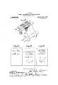
Patented D06. 4, 1917- 15 SHEETS- -SHEET 7.
flEN TOR.
WITNESSES A TTORNE YS.
J. R. PEIRCE.
MACHINE FOR RECORDING 0R LISTJNG ITEMS ON CARDS.
nrrucmon rm AUG-30, ma.
1,248,902, v Patented 1m 4,1917.
1'5 SHEETS-SHEET 9.
W 1 TNESSES q A I ATTORNEYS J. R. PEIRCE.
MACHINE FOR RECORDING 0R LISTING ITEMS ON CARDS. APPLICATION rum/wean. 1913.
1,248,902. Patented Dec. 4,1917.
l5 SHEETS-SHEET I0 WZTNESSES: I p fl YVENTOR. W. y M v I MATTORNEYS.
1. R. PEIRCE.
MACHINE FOR RECORDING 0R LISTING ITEMS ON CARDS.
APPLICATION HLED AUG-30. 1N3- Patented Dec. 4,1917.
I5 $NEETSSNEET II @VENTOR.
5. O 00 I 0 8a A 000 0 5. o o 2 Ir! 5 oo 9 II! o Xu I-I|S|I O 000 I .l 2 O O F A 6 o 0000 2 1W 0 o A C \|l 5 0o 8 m 00 2 w o 1 89. m 0a 0 L 8 .l n T I. o F. T. i O 2 n I P D //IIII M m 8 u M A A W S A L: a A C WITNESSES: m I
. V TTORNEYS.
1. R. PEIRCE.
MACHINE FOR RECORDING 0R LISTING ITEMS ON CARDS. APPLICATION FILED AUG-30. I913.
1,248,902. Patented Dec. 4,1917.
I5 SHEETS-SHEET l2.
- I INVENTOR.
e TTORNE YS.
WITNESSES J. R. PEIRCE.
MACHINE FOR RECORDING 0R LISTING ITEMS ON CARDS.
APPLICATION I'ILED AUG.3 I9I3.
Patented D00. 4, 1917.
I5 SHEETS-SHEET I3- TOR 5 w m m W .I. R. PEIRCE.
MACHINE FOR RECORDING 0B LISTING ITEMS ON CARDS. APPLICATION HLEO AUG. 30. 1913.
1,248,902. Patented m4. 1917.
I5 SHEETS-SHEET I 4- WITNESSES Z ATTORYEYS.
1. R. PEIRCE. MACHINE FOR RECORDING 0R LISTING ITEMS ON CARDS.
APPLICATION I'ILED AUG.30| I913- Patented 4,1917.
I5 SHEETS-SHEET I5- F .INVENTOR.
JoHN ROYDEN PEIRCE, E NEw YORK, N. Y., ASSIGNOB T0 rEInoE rarEN'rscomm, A CORPORATION OF NEw YORK.
MACHINE ron :aEcoEDINe on msrriNerrEms 0N, chains.
To all whom it may concern." Be it known that I, JOHN ROYDEN PEmoE, a citizenof the United States, and a resident of the city, county, and State of New York, have invented new and useful Improvements in Machines for Recordin or Listing Items on Cards, of which the to lowing is a specification. p In a previous Patent, No. 998,631 of July 25, 1911, I have described an apparatus for rinting and punching cards which are to e used to control, through their perforations, the subsequent operations in accounting or statistical machlnes." In my pending application, No. 331,757, filed August 23,- 1906, I have covered broadly a perforating and printing machine using separate and 1ndependent perforating devices, devices for printing on the card indications corresponding to the perforations and mechanism actuated by keys for controlling both a printing and a perforating operation; The present invention is a deve opment, with certain modifications, of the machines described insaid patent and said pending application.
In the aforesaid patent the system of perforations used in most ofthe columns of the card is a simple one, using a separate hole space for each of the nine digits. The resent machine is'designed to use only four iiole spaces for thenine digits, some of the digits being represented by combinations-o1 erforations in two or more of the spaces. his secures a much more compact card and machine; or permits the indicating of more.
information upon a card of given size. I
The machine is of the key-board type and has an automatic feed for the cards.
the necessary keys, which setsthe printing and perforating mechanism in correspondmachine may be operated by hand or by a-..
motor. When it is to be operated by hand certain devices are provided for retardlng vent accidental injury to the machine, which Specification of Letters l latent.
.zontal section.
For, each card the operator has merely to push Patented Dec. 4, 1917.
Application aiea'au iist 30.1913. Serial No. 787,456.
precautionary devices are not necessary with a motor. According to the present invention means are provided for rendering these precautionary devices inoperative so as to permit the change of the machine from hand operation to motor operation.
The complete machine is accurate and easy and fast of operation. The accompanying drawings illustrate embodiments of-the inventio c i Figure 1 is a perspective view of the machine omitting certain details for the sake of clearness.
Fig. 2 is a plan with a part of the casingremoved and part of the mechanism in hori- Fig. 3 is a longitudinal section approximately on the line H'of Fig. 2.
Fig. 4 is a longtiudinal section approximately 011 the line 4.4 of Fi 2.
Fig. 4* is an enlargement o a part of Fig. 4, showing the construction of the punches and immediately related mechanism.
Fig. 4 is a side elevation of the mechanism for shifting the card vertically, the plane of this figure being approximately on the line-1." ofFig. 2.
Fig. 4 is a rear elevation of .a backing plate for the card.
- .Fig. 5 is a longitudinal section approxi- Fig. 5 is a detail of Fig. 5, shown separately for greater clearness.
Fi 6-is a vertical transverse section approximately on the line 6-6 of Fig. 2 omitting certain parts for the sake of clearness.
Fig. 6 is aside elevation of the mechanism for stopping the movement of the card in its recording position. i
Fig. 6 is a transverse section showing the main shaft and plates carried thereby.
Figs. 7 and 8 are perspective views of detai s.
' Figs. 9 to 13 inclusive are side elevations of details.
I Fig. lrhiS a plan of parts of Fig. 11.
- Fig. 15 is a. perspective view of a detail.
Figs. 15' and 15 are diagrams showing the clip in successive positions.
Figs. 16 and 17 are perspective views of details.
Figs. 18 to 20 inclusive are front elevations of a card in the successive stages of the operation.
Fig. 21 is a perspective view of the ma- 5 chine with a cash register attachment applied thereto.
Fig. 22 is a side elevation, partly in section, of the cash register attachment.
Fig. 23 is a plan of the same, partly in section.
Fig. 24 is a horizontal section of the dials, and connections of the cash register attachment.
Fig. 25 is a perspective view of the machine of Fig. 1 with a listing attachment added thereto.
Fig. 26 is a side elevation, partly in section of the listing mechanism applied to the printing and punching machine.
Fig. 27 is a plan of a rear part of Fig. 26.
Fig. 28 is a detail of the mechanism for feeding the strip on which the list is made.
Referring now to the embodiment of the invention illustrated, the machine has at the rear pockets or guideways for the cards A, one at the left for receiving the blank cards containing printed titles of the different items which are to be recorded thereon, and one at the left for receiving the cards upon which the various numbers and amounts have been printed under the appropriate titles and which have been correspondingly perforated. A card is shown also inthe middle position in which the recording operation takes place.
On the front portion of the machine is a key-board containing recording keys B from 1 to 9 (zero being recorded when no key is pressed). At the front of the key-board there is located an accumulator C which carries the total of certain numbers recorded on the successive cards. A total button D is arranged adjacent to the key-board which, when pressed, causes the printing of the total and causes the accumulator to return to zero so as to start a new total thereon. The main shaft E projects slightly at the right of the casing and may carry a handle F (Fig. 3) which is pulled forward and released for each recording operation. Or the.
handle may be removed and the shaft con nected with a motor designed to oscillate the shaft at the proper rate. Adjacent to the key-board is a pull-up G which throws out of operation certain controlling devices which are necessary when the machine is operated by hand, but not when it is operated by motor. At the right of the keyboard is a long button or strip H which is pressed to start the motor after the desired keys for any recording operation have been pressed.
Card. feeding.-The cards A are introduced into the left hand pocket J (Figs. 2 and 6) and pressed forward by a weight,
spring or other suitable device toward the front of the pocket. Fig. 18 shows the card at this stage. The foremost card in the pocket J is shifted to the center of the machine in the vertical plane of the recording apparatus and then downward to bring an upper portion thereof in line with the recording devices and the latter are operated to form the upper printed line thereon (the numerals 24 139 and 285) and to form an upper set of perforations corresponding to said numerals. The card after receiving this first line of the record is indicated in Fig. 19. It is then lifted and a second line of records applied thereto consisting, for example, of the numerals 16, 27, and 53.40 and the corresponding lower set of perforations as indicated in Fig. 20. The system of perforations in four hole spaces to correspond with the numerals is fully described in my previous application No. 666,944, filed December 20, 1911, and others, and need not be further described here. Any system of combinations of either four or more hole spaces may be used. The position of the card for the recording of the second line is indicated in dotted lines in Fig. 19. The recording devices act always in the same horizontal plane so that by shifting the card downward the first line is recorded and by thereafter shifting it upward the second line is recorded below the first. From the dotted line position of Fig. 19 the card is shifted horizontally to the right and enters the front of the right hand delivery pocket K, forcing back the previous cards therein against a weight or spring or the like; whence the cards may be removed from time to time as desired.
In order to withdraw the foremost card from the supply pocket J it is n'rst engaged at its left hand edge by a pusher which gives it a slight movement to the right after which its projecting edge is seized at the top and bottom by CllPS which pull it over to I the middle position. There is a front wall L upon this pocket for preventing the cards from being pushed out, this front wall L having a pro ection M extendin beyond the rear edge of the card in the mi dle position of the latter so as to hold it against a backing plate N which forms the platen against which the printing is done. The plate L, M is fastened to an intermediate frame by means of pins 0 projecting forward from the plate to stationary uprights 106 (Fig. 2). A similar pair ofclips engages the right hand edge of the card which is in the middle osition and simultaneously pulls it to the rlght into the pocket K.
The pusher P is illustrated in Figs. 2, 5 and 6. It overlaps the foremost card in the pocket J and is. provided on its inner face with a projection Q of approximately the same thickness as a card and adapted, in the retracted position of the pusher, toengag'e the rear edge of the foremost card. The pusher is guided at top and bottom upon a pair of transverse rods .R and S and is pivotally connected at its rear with a horizontal arm T on a short vertical shaft U which is oscillated at suitable intervals throu h connections at its lower end hereinafter el scribed. This causes a movement of the pusher sufiicient to slightly advance the foremost card to the right. 1
In this position the card is caught by grippers, the upper one of which is indicated in Fig. 15 and comprises an inner jaw V fixed on a short upwardly extending shaft W, and an outer jaw X pivoted on the same shaft and pressed toward the jaw V by means of a. tension spring Y between a pin on the shaft and a tail on the jaw. A in Z bears against a projection a on a. ame carrying the shaft W to limit the backward movement of the jaw X. The shaft W is carried in a horizontal projecting portion 6 of the frame 0, and the shaft carries at its upper end a lever d which connected through a link 6 with a similar lever f on the upper end of a shaft, 9 which carries the gripper h, j-which pulls the card from the recording position to the discharge pocket. Connected to the lever f is a tension spring k which connects it with a hook Z pivoted on the frame 0 at its rear end and having a lug m which in the retracted position shown in Fig. 15 bears against a fixed pin a projecting downward from the top of the easing (see Fig. 6) so as to stretch the spring is. Thus in this position the link e'is pulled to the'left and the shafts W and g are turned to swing the clipsv toward the front of the machine. This movement of the link 6 to the left is limited by the stop pin 0. on the frame 0. The bent lever f carries a pin 7) which in this position engages the end of the hook Z and holds the latter in retracted position after the frame carrying the grippers moves to the left and away from the pin n. Thus near the'end of the right hand movement of the clips the pin a causes them to be shifted forward beyond the plane of the cards and the .pin ;0 holds them in this forward position during the left hand movement of the frame so as to avoid interference with the cards which have been fed. Near the end of the left hand movement the clips are shifted back to the plane of the cards and openedby means of cam mechanism supported from the top part of the casing of the machine. The cam g is pivotally suspended at r and pulled backward by the spring 8 connected to anarm of a hook t which is pivotally supported from the top of. the casing by a pivot u and the forward end of which engages a pin '0 on the underside of the cam. The bent lever d on the shaft W carries a roller to which,
near the end of the left hand movement of the frame, strikes the inclined face of the cam g and is deflected to the rear. This turns the shaft W and the jaws V and h of the clips backward to their'extreme position. They are followed by the jaws X and j until the latter are, stopped by the pins Z striking the projections 0;; the jaws V and 72. moving farther. Thus the clips are shifted back into the plane in which the cards are to be fed'and arealso opened to pass over the edges of the cards. The action of the arm also causes the pin 2 to be swung backward, camming over the inclined end of the hook- Z and passing a slight distance beyond the shoulder of the hook.
After the clips have been opened and shifted sufliciently far to the left to embrace the edges of the-cards a pin on the clip-carrying frame strikes the hook t and releases the cam g which is forced outward by the spring is acting on the roller w. The
outward movement of the roller 10 is stopped when the pin 1) strikes the shoulder of the hook Z. This outward movement of the roller w is sufiicient to swing the jaws V and 7:. forward sufficiently to grip the cards against the jaws X and j. The frame is then shifted to the right until near the end of its movement it strikes the pin a and the previous operations are repeated. The cam being the position of the card at the end of a feeding movement. In the third position the cardhas been stopped at the end of a feeding movement, but the clip 5 V, Xv has moved to the right and by the action of the fixed pin n has been swung forward out of the plane of the cards. In Fig. 15 the first position, at the right of the figure, shows the clip beginning its rear ward movement. I The second position shows it with the jaws Vand X open just before reaching the edge of the card and the third position shows them still open and embracing the edge of the card.
The frame 0 carries rollers y which travel on the rod R, .Fig. 6. A similar frame 0' is located immediately below the frame, 0 andvconnected thereto by a stiff plate 2 so that the two frames move together, the rollers of the lower frame traveling on the rod S. The shaftg which carries the right hand cli h, j is extended downward into .the lower frame.0' (see Fig. 3) where it carries a similar clip,.and the lower clips are connected to each other by arms and links similar to the parts a, d and 7' shown in Fig. 15. Thus the lower clips and the upper clips partake simultaneously of the same movements. In shifting the card from recording position into the delivery pocket K the forward face of the card bears against a plate 1 with a portion 2 overlapping the card in the recording position. the plate 1 being attached to the right hand wall of the pocket K by a flange 3 shown in Fig. 3. he movement of the card is stopped by the right hand wall of the pocket K. After the card strikes this wall and'is stopped the clips 11, j continue to move to the right and slip off the edge of the card before they are swung forv-card for the return movement.
The card in the recording position similarly stopped by striking a stop 3 (Figs. 6 and (3) which is withdrawn to permit the advance of the card to the delivery pocket and which is thereafter immediately advanced to limit the movement of the. next card to its recording position. The opening 5 in the card-holder N is provided with an upward extension 5 to permit the card-holder to shift downward without interference from the stop 3. This stop extends rearwardly from the card-holder and has a slot 3 through which passes a headed pin 3 fastened in the right hand supplementary frame 12 whereby the stop is held against the frame and guided to prevent longitudinal movement. The rear end of the stop 3 is attached to the upper arm of a lever 3 pivoted in the same frame 12 and carrying at its lower end a link 3* which has a pin 3 connected by a spring 3* to apin 3 projecting upward through a slot in the link 8 and mounted on an arm 3 fixed on the vertical shaft 23 which effects the lateral shifting of the clips. As the shaft 23 swings to shift the clips and feed the cards from left to right the pin 3 commences to put a tension on the spring 3 and to push the stop 3 forward; but the card which was in recording position is advanced over the end of the stop before the latter commences to advance. As the movement continues the 'stop is pressed forward with a light spring pressure against the card which is advancing over its end. As the card is advanced beyond the end of the stop the latter springs forward and stops the cards in proper position. On the return movement of the clips the pin 3 shoves the link in the opposite direction and withdraws the stop.
In the recording position the card lies between the back plate N, previously referred to, and the forward perforated plate 4 which is fixed in the plane of the projections .M and 2. The back plate N (Figs. 4, 4 and 6) is provided with a wide slot 5 in which lies a fixed perforated plate 6 with its perforations registering with those in the front plate 4, and carrying the punches '7 (Figs. 4 and l The front of the plate N is provided at top and bottom with grooves S in which the clips travel while advancing the cards and with forwardly projecting edges 9 which extend over the top and bottom edges respectively of the card in its middle position and by which the card is first lowered to bring its upper line in recording position and then raised to bring its lower line into recording position. Upon the back of the plate N, Fig. 1 there are provided guide strips 10 which have slots engaging pins 11 on a supplementary fixed frame 12. The strips 10 have at their outer edges ears 13 connected by a pin and slot to arms 1 1 mounted at opposite ends of a shaft 15 fixed on said supplementary frame 12, and oscillated at suitable intervals.
The movement of the shaft 15 is secured by the following mechanism. On its right hand end (Fig. 4 is .an arm 16 which is connected to a link 17 extending rearwardly' and attached to the u per end of a lever 18 pivoted at an interme iate point of its length and having at its lower end an ear 19 with a slot in which is located a pin on the end of a horizontal lever 20 pivoted at an intermediate point of its length and connected by a pin and slot at its opposite end to a link 21 which is operated through suitable intermediate devices from the main shaft E. On the first operation of this shaft the back plate N carrying the card is lowered and the first line of the record is made. On the second operation of the main shaft the back plate and card are raised and the second lineof the record is made. All alternating mechanism is, therefore, necessary, so that the link 21 will be reciprocated on alternate operations of the main shaft.
The movement of the clips must also occur only upon alternate operations of the main shaft. On the first movement of the shaft the clips operate and advance a card to recording position. The clips continue their movement to a point beyond the plate N (Fig. 6) and the latter then moves down ward and thus lowers the card for the first punching operation. The clips have no vertical movement. On the second movement of the handle the back plate N lifts the card for the second punching operation, but the movement of the clips is suppressed. On the third operation of the handle the feeding movements of the first operation are repeated, etc. The frame a carrying the clips is connected by a pin and slot (see Fig. 2) to a horizontal arm 22 on the u per end of a vertical shaft 23 at the rear of the machine, the lower end of said shaft 23 carrymg an arm 24 connected by a lever 25 to a link 26 running forward to a point adjacent to the hand shaft E. The link 26 is operated alternatively with the link 21 for securing vertical movementof the card. The vertical shaft 23 has also an arm 27 connected by a link 28 to an arm 29 on the lower end of the shaft U by which the movement of the pusher is secured. 4
The forward ends of the links 21 and 26 are illustrated in Fig. 16 and the controlling mechanism therefor in Figs. 3, 9 and 11 to 14. The forward end of the link 21 is provided with a slot 30 near its upper edge, the forward end of this slot being turned down. The link 26 is provided with a slot 31, the forward end of which is turned up. A pin 32 is carried on a lever 33 frictionally mounted on a shaft 34 on the lower end of an arm 35 which is fixed on a shaft 36 carrying an arm 37 .(Figs. 3 and 9), the lower end of which has a pin bearing on a cam 38 which turns freely on a shaft 39 and which cam is connected by a link 40 with a plate 41 loose on the main shaft E, but partaking of the motion thereof in the manner hereinafter described. When the main shaft is turned forward the cam 38 turns upward and after a first idle movement permits the arm 37 to swing to the rear. A spring 42 (Fig. 4) is connected to certain slides hereinafter referred to, engaging a cross bar 43 which extends between the lower ends of arms 4.4 on the shaft 36. Thus when the cam 38 permits it the, shaft 36 is turned so as to swing the arm 35 to the rear. The pin 32 being in the position of Fig. 16, this movement of the arm 35 pushes the link 26 to the rear and operates the pusher P and clips to feed the card laterally. During this movement the pin 32 moves freely through the slot 30 without action on the link 21 and vertical feeding plate N. At the next operation the pin 32 1s swung downward while the arm 35 is in its forward position, so that as this arm swings to therear it pushes back the link 21 and causes a downward movement of the plate N carrying the card, and on its return an upward movement of the same card, the pin 32 working freely in the slot 31 so as to have no effect on the link 26 and the lat-' eral feeding mechanism.
The shifting of the pin 32 upward and downward on alternate operations of the shaft is effected by the'mechanism of Figs. 3.and 11 to 14. The shaft E carries a plate 45. To the right of this plate is a pin 46 fixed in a supplementary frame 51 (Fig. 2) on aging an oblique slot in a hook 47 with a aring mouth or notch, the hook being pivotally mounted on a plate or arm 48 which is connected with an opposite arm 49, the two being frictionally mounted on a pin 50 which is mounted in the supplementary frame 51. At the outer ends of the arms 48 and 49 are pivoted pawls 52 and 53 respectively connected to each other by a spring 54. On the right hand face of the Y plate 45 are pins 55 and 56' projecting into the plane of the pawls 52 and 53.
In the'starting position (Fig. 3) the hook 47 is in the forward position relatively to the pin 46 and, by reason of the obliquity of the slot, is in its lower position. The pin 57 on the forward end 0 the lever 33 lies within the hook 47. Therefore, this pin 57 like the hook 47, is in its lower position, an
the pin 32 at the opposite end of the lever 33 is in its higher position. During the first part of the forward stroke the cam 38 (Fig.
the arm 35 as in Fig. 3, with the pin 57 in the hook 47 But during this first portion of the stroke the plate 45 swings to the front,
.9) merely holds the shaft 36 stationary and the pin 55 swings the arm'48 upward and the hook 47" is pulled to its upper position (Fig. 11), carrying with .it the pin 57 and depressing the pin 32 before the. rearward.
movement of the arm 35 commences.
At the end of the first forward stroke of the handle the parts are in the position of Fig. 11. The arm 35 has swung to its rear position and carried with it the link 21, causing a downward movement of the plate N carrying the card. On the first backward stroke of the main shaft the arm 35 swings forward pulling the link 21 forward and raising the plate'N and card. The end ofthis forward stroke is shown in Fig. 12. The pin 57 enters the hook 47. The plate 45 moves backward on this stroke without effect except to bring the pin 56 into the notch of the pawl 53.
On the second forward strokethe cam 38' is idle during the first part'of the movement as before so that the arm 35 remains in the forward position with the pin 57 in the notch 47 while the plate 45 is swinging to the forward position and the pin 56, in pasing from the position of Fig. 12to Fig. 13, swings thearm 49 and the arm '47 downward and throws the hook 47 downward and part'sto At the end of this stroke the parts are again in the position of Fig. 3. I The thirdoperation of the machine is, therefore, a repetition of the first, and the fourth operation a repetition of the second,
etc. The recording operation takes place on each stroke.
Punching mechanism.Thepunches 7 are mounted in the manner indicated in Fig. 4. Their heads lie normally in the perforations
Priority Applications (1)
| Application Number | Priority Date | Filing Date | Title |
|---|---|---|---|
| US78745613A US1248902A (en) | 1913-08-30 | 1913-08-30 | Machine for recording or listing items on cards. |
Applications Claiming Priority (1)
| Application Number | Priority Date | Filing Date | Title |
|---|---|---|---|
| US78745613A US1248902A (en) | 1913-08-30 | 1913-08-30 | Machine for recording or listing items on cards. |
Publications (1)
| Publication Number | Publication Date |
|---|---|
| US1248902A true US1248902A (en) | 1917-12-04 |
Family
ID=3316648
Family Applications (1)
| Application Number | Title | Priority Date | Filing Date |
|---|---|---|---|
| US78745613A Expired - Lifetime US1248902A (en) | 1913-08-30 | 1913-08-30 | Machine for recording or listing items on cards. |
Country Status (1)
| Country | Link |
|---|---|
| US (1) | US1248902A (en) |
Cited By (3)
| Publication number | Priority date | Publication date | Assignee | Title |
|---|---|---|---|---|
| DE741983C (en) * | 1935-07-31 | 1943-11-27 | Mercedes Bueromaschinen Werke | Card punching machine with counter |
| US2521372A (en) * | 1945-10-03 | 1950-09-05 | Ibm | Punching machine |
| US3143060A (en) * | 1961-06-06 | 1964-08-04 | Vip Inc | Card printing and punching device |
-
1913
- 1913-08-30 US US78745613A patent/US1248902A/en not_active Expired - Lifetime
Cited By (3)
| Publication number | Priority date | Publication date | Assignee | Title |
|---|---|---|---|---|
| DE741983C (en) * | 1935-07-31 | 1943-11-27 | Mercedes Bueromaschinen Werke | Card punching machine with counter |
| US2521372A (en) * | 1945-10-03 | 1950-09-05 | Ibm | Punching machine |
| US3143060A (en) * | 1961-06-06 | 1964-08-04 | Vip Inc | Card printing and punching device |
Similar Documents
| Publication | Publication Date | Title |
|---|---|---|
| US2624273A (en) | Checking means for interpreters | |
| US1248902A (en) | Machine for recording or listing items on cards. | |
| US2555734A (en) | Automatic justifying typewriter | |
| US2346250A (en) | Accounting machine | |
| US1547150A (en) | Cash register | |
| US2554827A (en) | Ticket issuing machine | |
| US1327520A (en) | Strip-feeding mechanism | |
| US2555732A (en) | Dual record feeding device | |
| US2862708A (en) | Multiple form drive | |
| US2182006A (en) | Tabulating machine | |
| US2336111A (en) | Tabulating machine | |
| US1980160A (en) | Projector for type bar printers | |
| US1182309A (en) | Perforating and printing machine. | |
| US1998281A (en) | Record card-controlled business machine | |
| US1200129A (en) | Feeding mechanism for recording-machines. | |
| US3552738A (en) | Apparatus for processing cards having printed and recorded data | |
| US2110855A (en) | Paper feeding device | |
| US2709959A (en) | Four-line printing mechanism | |
| US2239023A (en) | Power-driven writing machine | |
| US1497482A (en) | Transportable typewriter | |
| US511374A (en) | taylor | |
| US1876969A (en) | Machine for printing addresses or other matter on forms or the like | |
| US1843964A (en) | Paper folding mechanism | |
| US2100579A (en) | Manifolding device | |
| US1876056A (en) | Paper feeding mechanism for listing machines |