US1237998A - Automatic telephone system. - Google Patents
Automatic telephone system. Download PDFInfo
- Publication number
- US1237998A US1237998A US77506713A US1913775067A US1237998A US 1237998 A US1237998 A US 1237998A US 77506713 A US77506713 A US 77506713A US 1913775067 A US1913775067 A US 1913775067A US 1237998 A US1237998 A US 1237998A
- Authority
- US
- United States
- Prior art keywords
- circuit
- group
- lines
- switches
- busy
- Prior art date
- Legal status (The legal status is an assumption and is not a legal conclusion. Google has not performed a legal analysis and makes no representation as to the accuracy of the status listed.)
- Expired - Lifetime
Links
- 238000004804 winding Methods 0.000 description 27
- 239000004020 conductor Substances 0.000 description 7
- 230000033001 locomotion Effects 0.000 description 5
- 230000007246 mechanism Effects 0.000 description 2
- 241000272470 Circus Species 0.000 description 1
- 101100289061 Drosophila melanogaster lili gene Proteins 0.000 description 1
- 101100001674 Emericella variicolor andI gene Proteins 0.000 description 1
- 241000735495 Erica <angiosperm> Species 0.000 description 1
- BGPVFRJUHWVFKM-UHFFFAOYSA-N N1=C2C=CC=CC2=[N+]([O-])C1(CC1)CCC21N=C1C=CC=CC1=[N+]2[O-] Chemical compound N1=C2C=CC=CC2=[N+]([O-])C1(CC1)CCC21N=C1C=CC=CC1=[N+]2[O-] BGPVFRJUHWVFKM-UHFFFAOYSA-N 0.000 description 1
- DCCRHRRPKQISNG-UHFFFAOYSA-N Ruine Natural products COC1=CC=C2C3=CC=NC(C)=C3NC2=C1OC1OC(CO)C(O)C(O)C1O DCCRHRRPKQISNG-UHFFFAOYSA-N 0.000 description 1
- 102000003800 Selectins Human genes 0.000 description 1
- 108090000184 Selectins Proteins 0.000 description 1
- 241001080526 Vertica Species 0.000 description 1
- 230000009471 action Effects 0.000 description 1
- 230000006978 adaptation Effects 0.000 description 1
- 238000012986 modification Methods 0.000 description 1
- 230000004048 modification Effects 0.000 description 1
- AAEVYOVXGOFMJO-UHFFFAOYSA-N prometryn Chemical compound CSC1=NC(NC(C)C)=NC(NC(C)C)=N1 AAEVYOVXGOFMJO-UHFFFAOYSA-N 0.000 description 1
- 238000009877 rendering Methods 0.000 description 1
- 230000004044 response Effects 0.000 description 1
- 230000000284 resting effect Effects 0.000 description 1
- 230000011664 signaling Effects 0.000 description 1
- NWONKYPBYAMBJT-UHFFFAOYSA-L zinc sulfate Chemical compound [Zn+2].[O-]S([O-])(=O)=O NWONKYPBYAMBJT-UHFFFAOYSA-L 0.000 description 1
Images


Classifications
-
- H—ELECTRICITY
- H04—ELECTRIC COMMUNICATION TECHNIQUE
- H04Q—SELECTING
- H04Q3/00—Selecting arrangements
Definitions
- My invention relates to improvements in automatic telephone systems, vand more particularly to an improved type of switch for use in such systems which is ena-bled not only to select an idle contact from among aA group of such contacts, but is enabled to select an idle contact in any one of a number of such groups.
- a further feature of my invention is its adaptation to what is known as arrotary connector-that is, a connector which, on
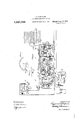
- Figure l is a diagrammatic layout of a telephone system in connection with which I have chosen to illustrate my invention.
- Figs. 2 and 3 taken together show a complete .connection established through automatic switches embodying the principles of my invention, with a trunk line leading to' a manual 0r private branch exchange such as shown at W in Fig. l.
- Fig.y 4 is a detail view showing a portion of the selector' auxiliary bank of contacts.
- Fig. 5 is a sectional view taken on the line 5--5 in Fig. 4,
- Fig. 6 is a detail view of a portion of the connector bank contacts.
- Ihe telephone system illustrated in Fig. l comprises an automatic exchange M and a manual exchange or exchanges W.
- y rIhe manual vexchanges are represented by manual switchboardsW and W2 and are provided With suitable cord circuits N and N for establishing connection between said manual eXchangesW and the automatic exchange M.
- yIt is thought unnecessary to explain in detail the operations of the Irranual apparatus used in this system, as they are generally well known.
- the automatic exchange M is ⁇ of a well-known type, comprising subscribers ⁇ individual switches, irst selector switches, second selector switches and connector switches.
- the system is also provided with a plurality of connectors which are adapted to select trunks leading to the manual exchanges W.
- connector switches reprebanks of contacts ytors are represented, while the banks of the' second selectors and connectors are shown on a scale oi three to ten. All of the line switches vbel inging to one group of subscribers lines (the line switches C2, for example) have common access to a group of first selectors, such as the selectors E2.
- the bank contacts of the first selectors E2, E5, etc., of corresponding roups pr hundreds are multipled throug out the differ-
- the first levels vof these first selectors are connected to trunk lines leading to second selector switches associated with the first thousand, the second levels of the first selectors are connected to trunk lines leading to the second selectors associated with the second thousand, and
- the third level is connected to trunk lines the third thousand (not shown).
- sixth and' seventh levels are multipled to-y gether and extend to a plurality of con! nector switches shown at HS. rlhe connectors H3 in turn have access to the trunk lines leading to the manual board W2.
- the first selector levels 8, 9 and 10l are also multipled together and extend to a plurality of connectors'shown at H', which connectors have access to trunklines lead- ⁇ ing to the manual board W".
- the automatic substation A (Fig. 2), which we will assume is in group A2, comprises the usual receiver 2,
- This'line switch comprises, among other details, a plunger (not shown) attached to the end of a so-called plunger arm 9 which is controlled by the magnet 10.
- the magnet 10 comprises four windings, namely, a pull-down winding 11, cut-off or holding winding 12, line winding 13 and auxiliary winding 14.
- the .core of the magnet 10 is so constructed that the magnetic circuit of the windings 11 and 12 is ⁇ separate from that of the windings 13 and 14.v
- the winding 11 operates both the plunger arm 9 and the armature 15, while the winding 12 is only strong enough to o erate the cut-off armature 15 and to hold t e plunger arm 9 in its operated posibeen operated.l
- the plunger arm 9 When the plunger arm 9 is operated, the plunger is forced into the bank of contact springs, forcing the springs 16, 17, 18V and 19 into engagement, respectively, with the springs 20, 21, 22 and 23.
- each line switch is providedt'with a plurality of such sets, each set a trunk line leading to a first selector switch E.
- Each trunk line is connected in multiple to the correspondline switches of the which are controlled by the master switch D.
- the switch C is controlled by the subscriber through the medium of the line relay 13, as will be hereinafter more fully explained.
- the master switch D is of the same general type as that disclosed in British Pa'f..,nt No. 26,301 of 1906, referred to above, being, however, of the particular type disclosed'in the above-mentioned British Patent No. 1419 of 1910.
- the function of the master switch is to maintain the plungers of all the idle line switches in posipion to engage the terminals of an idle trunk ine.
- the first selectorl switch E is of the general type of selector switch disclosed in United States Letters Patent No. 815,321, issued March 13, 1906, to Keith, Erickson and Erickson, the circuits being modified, however, to operate in a system embodying the principles of my invention.
- the selector E comprises a bank of line contacts arranged in horizontal rows group yswitch shaft is operated raeaeee or'levels, which contacts are adapted to be engaged by a set of wipers 25 and 27 carried upon a shaft (not shown) which rhas a vertical movement controlled by the vertical magnet 28 and a rotary movement controlled by the rotary magnet 29.
- Means for automatically interrupting the circuit of the vertical magnet 28 is provided in the relay 105, as will be hereinafter explained.
- the selector Eis provided with an extra sha ft wiper 71 and an extra set of bank contacts a, as shown in Fig. 2.
- This extra bank of contacts consists of ten groups or levels, the same as the line and private banks, each group comprising tenlegen-sof contacts.
- the shaft wiper 71 is provided with a pair of wiping arms which engage with the two contacts of each pair and thus connect them together. In order to enable the switch to automatically'step from one level to another, lthe corresponding levels in this extra bank of contacts are wired in a particular manner.
- I also provide a series of contacts 71a (Fig. 2), there being one of these contacts for each of the levels 4, 5 and 6-that is, one for each level above which the wipers may be automatically raised, which contacts are adaptedtc be engaged by the wiper 72 carried by the switch shaft. If it were desired to have not only the fourth, fifth and sixth levels so arranged, but also the first, second and third, the contacts 71a would be adapted to bel engaged by the wiper 72 afterthe vertically one step,
- the wiper 71 is a short-circuitingwiper-that is, a wiper the function of which is ⁇ to eletrically connect the upper and lower contacts of any set in the extra bank upon which it may stop in the fourth, fifth and sixth levels.
- W'ith the selectors constructed inthis manner they are enabled not only to automatically select an 'idle trunk in the fourth level, but if all the trunks in that level are busy, to automatically move up to the next or fifth level and find an idle trunk there, or, if all the trunks in the fifth level are busy, to automatically pass to the sixth level, etc.
- the connector switch H (Fig. 3) is of the same general type of connector switch as that disclosed in United States Letters Patent No. 815,176, issued March 13, 1906, to Keith, Erickson and Erickson, the cir-y cuits, however, being modified toadapt the 'swltch to operate in a system in which the central office apparatus ⁇ is controlled by impulses delivered over the two sides of the line in series.
- the circuits are also modified to adapt the switch to operate in a system embodying the principles of my invention.
- the connector is provided with a shaft (not shown) carrying the wipers 36, 37 and 38.
- eingl a socalled rotary connectorand of a particular type used to illustrate my invention, it also carries the extra wipers 37a, 71b and 72.
- the shaft is controlled by the vertical mag-i net 39 and the rotary magnet 40, and the usual side switch comprising the wipersifl, 42, 43 and 44 is controlled by the private magnet 4:5 in the usual and well-known manner.
- the magnet 46 is the usual release magnet.
- the line relay 47 is connected to the line through the reversing springs of va so-called back-bridge relay 48.
- the ringing relay 49 is the means by which ringing current is applied to the called trunk or line, as the case may be.
- a busy signaling machine which supplies a circuit extends over the circuit just traced busy signal to the calling line through the to the bank spring 17, thence over the norniedium of the busy relay 120 in case the mal conductor 24 to said private bank concalled line is in use.
- a battery is tact.
- the energization of the relay 34 also shown which is for the purpose of Supplyprepares a circuit for the vertical magnct by 7e ing battery current for operating and talkbringing into engagement lthe springs 53 ing purposes.
- the connector is also proand 54 and opens the circuit of the release vided with a special contact bank d, shown magnet 31 at the spring55. in Figs.
- the vertical magnet receives four impulses 90 pull-down coil 11 in series with the auxiliary over this circuit and operates to raise the winding 14.
- the pull-down coil upon enswitch shaft and wipers four steps to a poergizing, attracts the plunger arm 9, thereby' sition opposite the fourth row or level of operating to close circuits through vthe bank bank contacts.
- the wiper of springs 16 to 23, inclusive. lt also oper- 72 engages the contact point 71"L of the' 95 ates the cut-oft armature 15, thereby disconf fourth level.
- the slow acting relay 35 is necting the line winding 13 from the line.
- This trols in part thel circuit of tbe rotary magnet circuit extends from ground vG2 through the 29 and is locked in energized position at this springs 52, bank springs 21 and 17, cut-off stage of the operation for the purpose of winding 12 to battery B, thence through batpreparing the circuit over which the rotary tery B to ground G.
- the winding 12, upon magnet 29 is subsequently to be operated.
- the relays 105 and 106 and the vertical magnet 28 energize over the circuit just traced.
- the vertical magnet upon energizing, operates to step theshaft and shaft wipers one stepthat is, to a point opposite the lifth level of bank contacts.
- the relay 105 upon energizing, interrupts its own circuit at the springs 104, therebyv allowing the vertical magnet to denergize. If the fifth level trunks are all in use, the spring 72 will again engage a grounded contact and the foregoing operations will be repeated to step the ⁇ shaft wipers to a point opposite the sixth level of bank contacts.
- the shaft will be raised still another step.
- the seventh level bank contact 71a will not be connected. Therefore this contact will have no guarding ground potential, whereupon rthe relays 105 and 106 and the magnet 28 will all dener- ⁇ gize.
- This circuit extends from ground G2 through the springs 52, 60 and .'39, 6l and 62, 64 and 63, 67 and 69, 69n and 67, interrupter springs 70 and the rotary magnet *.29 to battery B.
- the rotary magnet upon energizing, rotates the wipers one step and b v openingthe springs and the springs 59 and 60 disconnects the ground G2 If the first trunk line of this level is idle, the relay 66 Likewise, if-
- the private wiper 26 finds the contact with which it engages provided with a guarding ground potential which is transmitted to the relay 66 through the springs 63 and 64, thereby preventing it from denergizing.
- the rotary magnet denergizes when the springs 70 disengage regardless of Whether the relay 66 remains energized or not. If the relay 66 remains energized, the circuit of the rotary magnet will be again closed as soon as the armature drops back far enough to close the springs 70.
- the circuit ofthe line relay 47 When the connection is completed to the connector H, the circuit ofthe line relay 47 is closed.
- the relay 47 upon energizing, closes an energizing circuit through the slow relay 100.
- the relay 100 upon energizing, supplies a new holding ground Gr30 to the relay-58 of the selector E, the original circuit having been broken by the denergization of the relay 34 of the selector E.
- the energization of the relay 100 also prepares a circuit for the vertical magnet 39 and opens the circuit of the release magnet 46. lVhen the substation calling device is operated for the second digit 4, the circuit of the line relay 47 is momentarily broken four times. Since the relay ,100 is slow acting, it .does not denergize during the momentary ⁇ interruptions of its circuit by the relay 47,
- the contact 71 which corregrounded and the relay 121 will be held up sponds to the fourth bank level, will have a over a circuit extending from said ground ground potential upon it extending from at the private wiper through the side switch ground Gr7 through the shortcircuiting wiper 44 (in second osition) and the relay Wipers 71b (which are on the contacts of 121 to battery B. he relay 121, upon enthe fourth level) and thence to the contact ergizing, closes another circuit for ,the pri- 710.
- The'wiper 72 upon coming in contact vate magnet 45 extending from ground G9 with the grounded contact 71, closes a cirthrough the springs 122 'and 123, thence over cuit extending from said ground through a circuit heretofore traced throu h the magthe wiper 72, springs 109 and 110, relay nets 101 and 45 to battery B. he energi- 108a to the battery B.
- the relay 108 u on zation of the relay 121 also closes an Yene'renergizing, completes a circuit exten ing gizing circuit for the rotary magnet 40, the from ground G8 through the springs 111 relay 74 having denergized, as stated, said and 112, interrupter springs 113 and the recircuit extending from ground Gn'through lay 114 to the spring 1-15, and after the rethe springs 125 and 126, 127 and 128, 129 lay 74 denergizes, the circuit then extends and 130, 119 and 118, magnet 40 .andthe through the springs 115 and 116 to the verwiper 42 to battery B.
- The-rotary magnet, tical magnet 39 and the wiper 42 to the batupon energizing operates to rotate the shaft tery B.
- the relay 1088 upon energizing, wipers one step onto the next trunk line and also closes a circuit through the private magalso operates to close the circuit of therelay net extending from ground Grs through the 131 by the closure of the springs 124.
- the springs 111 land 112, relay 101 and the prirelay 131 upon energizing, opens the circuit vate magnet 45 to the battery B.
- the vertical 121 will remain energized, whereupon the magnet and the relay 114 operate in the operations of the rotary magnet and the resame manner asdescribed for the selector E la 131 will be repeated to rotate the shaft to raise the shaft wipers step by step until wipers onto an idle trunk line and the relay the wiper 7 2a finds a non-grounded contact, 121 will denergize and break the circuits of at which timethe relay 108a denergizes, the rotary magnet 40 and also of the cut-off thereby breaking the circuit of the private and private magnets 101I and 45, respecmagnet 45, thereby allowing the side switch tively, whereupon the private magnet will. to pass to second position, as stated.
- the wiper 44 upon passing to rotary magnet 40leaving the,apparatus in third position, supplies a' guarding ground readiness for the last digit 1. potential from ground Gra1 to the private After the second pause the calling device bank contact of the called line inthe banks l is.
- the realso disconnects the line winding 147 from lay 74 energizes as before to open the circuit the line;
- the rotary magnet energizes the called manual board W2, as shown by over the circuit above traced and steps the the heavy conductors.
- the relay 49 energizes over a will not pull up, and.
- relay 49 is intermittently energized over this circuit and operates to disconnect the calling line from the Called line and to intermittently connect the ringing current generator X with the called line.
- the operator at the board W2 answers the call andin so doing closes a bridge across the conductors 15.1 and 1521, whereby an energizing circuit 1s closed through the back-br1dge relay 48 of the connector H.
- rlhis circuit extends from ground G1 through the right-hand winding of the relay 48, thence through the springs 152 and 153, 155 and 154, conductor 152a to and ⁇ through said bridge at the board W2, back over the conductor 151, springs 145 and 146, 156 and 157, 158 and 159 and the left-hand winding of the relay 48 to battery B.
- the relay 48 upon energizing, operates to reverse the battery to the calling line.
- the relay 48 upon energizing, also operates to closevthe springs 160 and 161, thus closing an energizing circuit through the ringing cut-od relay 162.
- This circuit extends from ground G13 through the olf-normal springs 138 and 137 (closed upon the irst vertical step of the switch shaft), thence through the springs 160 and 161y and the relay 162'to battery B.
- f lhe relay 162 upon energizing, closes a locking circuit for itself independent of the springs 160 and 161 of the back-bridge relay, and also operates to open the circuit of the ringin relay 49, whereby the ringing current is sconnected :from the called line.
- 4the calling substation as follows: 'fireplacing of the. receiver on 'the Switch hook at the calling substation opens the circuit of-the connector line relay47 at the springs 163 and 164.
- the relay 47 upon dener i'zing, opens the circuit of the relay 100.
- 'e vrelay 100 upon denergizing, closes anenergizing circuit through the release magnet 46 and also disconnects the holding ground from the relay 58 and the winding 12 of the switches E and C, respectively.
- the circuit for the connector release magnet 46 extendsfrom ground Grs through the back contact of spring117, thence through the springs 75 and 166, off-normal springs 167 and 168 and the magnet 46 to battery l
- the magnet 46 upon energizing, disengages the retaining pawls from the shaft, allowing it to return to normal position.
- the shaft upon returning-to normal, opens the circuit of the release magnet 46 and also opens the circuit of the ringing cut-oli' relay 162 atthe springs 137 and 138.
- the relay 58 of the selector E upon ⁇ denergizing, Closes a circuit through the release magnet 31.
- This circuit extends from ground G ten trunks, for example, bu-L through the springs 183 and 182, 57 and 56, 53 and 55, 32 and 33 and the magnet 31 to battery B.
- the circuit of the release magnet is broken upon the shaft reaching its lowest position.
- the winding 12 of the line switch C upon deenergizing, allows the plunger arm 9and armature 15 to return to normal position, thereby leaving the apparatus in readiness for another call.
- the relay 120 energizes to open the rotary magnet circuit at the springs 118 and 119 and also closes a lookin circuit for itself extending from ground 13 through the springs 137 and 138, 139 and 133, 136 and 135, thence through the relay 120 and the wiper 42 to battery.
- This ground connection also extends from the spring 139 through the springs 140 and 141, thence over the circuit heretofore traced to the private magnet 45, thereby holding the side switch in second position.
- the relay 101 -which is in the private magnet circuit, energizes in this instance to keep the busy signal from the called line.
- the private magnet 45 upon energizing, operates to close a busy signal upon the calling line in the usual and wellown manner.l When the calling subscribe'r receives the busy signal, he restores his receiver to the switch hook and releases the apparatus as before.
- my invention contemplatingin its broader aspect the feature of a switch whiclris enabled to first automatically select groups and to then automaticallyselect an idle trunk in the selected group.
- a subscribers line a plurality of groups of trunk lines, a selector switch, means controlled by said -subscriber for operatin-g said switch t'o' s elect one of a plurality of said groups, and means for then moving said switch automatically to select another of said groups if fll the trunks in said first selected group are usy.
- subscribers lines Ina telephone system, subscribers lines, a plurality connector switches, a plurality of groups of trunk -lines extending from said selector switches to a series of said connector switches, a plurality of groups of lines extending from said connectors subscribers line, means controlled by a calling subscriber for extending the connection to one of said selectors and for then operating said selector to select one of Va plurality of groups of said trunk lines, means in said selector for then automatically selecting an idle group of said trunks andl for then selecting an idle trunk in the selected group to extend the connection to one of said means controlled by said subscriber for then operating the connector to select the desired group of lines extending to the called subscribers station, and means in said connector for then automatically selecting an idle group of said lines andk then selecting an idle line in, the selected group.
- a plurality of group ciated therewith having means for auto matically selecting idle groups, means for making a group busy, comprising a circuit a plurality o an autof of selector and to a called Y groupsy of lines,
- matically selecting idle groups means s of lines, a series of switches assocontrolled directly by a plurality of said switches.
- a plurality of groups of lines, a series of switches associated therewith. having means for automatically selecting idle groups, mean for making a group busy, comprising a circuit together with means individual to a' switch for directly controlling it.
- a telephone system a plurality of groups of lines, a series of switches associated therewith, having means for automatically selecting idle groups, means for making-a Ygroup busy, comprising a-circuit and banks for said switches through which said'circuit passes, said circuit controlled directly by a plurality of said switches, and means for making said switches common to the lines.
- a plurality of a series of switches associated therewith havingv means for auto matically selecting idle groups, means for making a group busy, comprising a circuit and banks for said switches through which said circuit passes, said circuit controlled directly by said switches and means' for making said switches common to vthe lines.
- AIn a telephone system a plurality of groups of lines, ⁇ a series of switches associated therewith, each having a progressively movable element, automatically selecting idle groups, means for making a group busy, comprising a link circuit controlled directly by one of saidvprogresslvely movable elements and means for making said switches common to the lines of a group.
- a plurality of groups of lines,.a series ⁇ of switches associated therewith, vhaving means for automatically selecting idle groups, means for making a group busy. comprising a link circuit 'and banks for said switches through which said circuit passes, said circuit controlled directly-by a plurality of said switches, and means for making said switches common to the lines.
- a plurality of trunklines divided into groups a selector switch lassociated therewith, means for automatically selecting an idle group, means for lautomatically selecting an idle ⁇ trunk in the group," and means ⁇ for making a group busy c. when all thelines therein have been seized,
- ⁇ 19 In a telephone system, a plurality of trunk lines divided into groups, a selector means common to Vthe,
- a selector switch associatedtherewith having a progressively movably element, means for automatically selecting an idle group, means for automatically selecting an idle trunk in the group, and means for making a group busy when all the lines therein have been movable elesaid switches rectly by said progressively ment and means for making common to the lines.
- a selector switch having a progressively movable element associated therewith, means for automatically selecting' an idle group, means for automatically selecting an idle trunk in the group, and means for making a group busy when 'all the lines therein have been seized, comprising a circuit controlled directly by said progressively l movable element, and means for 'making said switch common to the lines.
- a plurality of trunk lines divided into groups a selector switch associated therewith, means for automatically selecting an idle group-means selecting an idle trunk in the group, and means for making a group busy when all the lines therein have been seized, comprising a circuit and banks for said switches through which said circuit passes, said circuit controlled directly by a plurality of said switchesand means for making said switches common to the lines.
- a plurality of trunk lines divided into groups a selector switch associated therewith, means for automatically selecting an idle group, means for automatically selecting an idle trunk in the group, and means'for making a group busy when all the lines therein have been seized,
- a plurality of associated therewith having progressively movable means for automatically selecting an idle group, means for making a group busy, comprising a circuit controlled directly by said progressively movable means in the switch.
- a switch associated therewith having a progressively movable element, having means for automatically selecting an idle group, means for making a group. busy, comprising a circuit, said circuit controlled directly by said progressively movable element, and means for making said switch common to the lines.
- a switch associated therewith having means-for automatically selectingran idle group, means for making a group busy, comprising acircuit and a bank for said switch through which said circuit passes,"means individual to directly controlling said circuit, and means for making said switch Common to the lines.
- aplurality of trunk lines a series of switches each having a progressively movable element for connecting with said trunk lines, said trunk lines divided into groups, means comprisingl saidswitches for selecting an idle group and for selectingl an idle line in a' group, and means directly controlled by said propressively movable element for making a for automatically se ⁇ a switch for memes iliary circuit.
- a rotary connector switch a line leading to said switch, a group of line terminals in said switch, a group of trunk terminals in said switch divided into a ymovable member in said 4member to a sub-group of the trunk terminals, and if all the lines in that subgroup are busy t0 automatically and in'dependently of the line carry said member to a sub-group, all the lines of which are not busv and into engagement with a nonbusy line'therein.
- a line In a telephone system, a line, a calling device therefor, a trunk selector switch,
- a switch for tempes a group ol trunk terminals in said switch. another oup of trunk terminals in said switch divided intosubgroups, a movable member in said switch for connecting the line with the terminals in the switch, means controllable over the line from the calling device to carry said' member to the first group, and for automatically carrying the member over the busy terminals in said group whether all the lines in the group are busy or not, and means responsive to impulses from the calling device over the line to carry said member to a sub-group in a second group and if all the lines in that sub-group are busy. to automatically and independently of the line carry said member to another sub-group and into' engagement with a non-busy line therein.
- a telephone system a plurality of groups of lines, a series of switches associated therewith having means for automatically selecting idle groups, means for making agroup busy, comprising a circuit to- Uether with' means individual to a switch or directly controlling it, lsaid last means involving movable contacts under the control ot the switches.
- a telephone system a plurality of groups of lines, a seriesot switches associated therewith, having means for automatically selecting idle groups, means for making a group busy, comprising a link circuit together with means common to the linesr for directly controlling it, said last means involving movable contacts under the control of the switches.
- a telephone system a plurality of trunk'lines divided into groups, a selector switch associated therewith, means for automatically selecting an idle group, means for automatically selecting an idle trunk in the group, and means for making a group busy when all the lines therein have been seized, comprising a circuit together with means common to the lines for directly controlling it, said last means involving movable contacts under the control of the 'switches 4&1.
- a telephone system a plurality of trunk lines divided into groups, a selector switch associated therewith, means for automatically selecting an idle group, means for automatically selecting an idle trunk in the group, and means for making a group busy when all the lines therein have been seized, comprising a circuit together with means directly control- .groups of lines,
- a p plurality of a series of switches associated therewith having means for automatically selectin idle groups, means for making a group usy and means for making a group non-busy, one of said means compris'- ing a circuit controlled directly by a plurality of said switches.
- a telephone system a plurality of groups of lines, a series' of switches associated therewith having means for automatically selecting idle groups, means for making a group busy and means for making a group non-busy, one of said means comprising a circuit together with means individual toi a ⁇ ,switch for directly controlling it.
- a plurality of groups of lines, a series of switches associated therewith having meansfor automatically selecting idle groups, means for making a group busy and means for making a group non-busy, one of said means comprising a circuit controlled directly by the switches, and means for making said switches common to the lines of the group.
- a telephone system a plurality of groups of lines, a series of switches associated therewith having means :tor automatically selecting idle groups, means for making a tgroup busy and means for making a group non-busy, one of said means comprising. a circuit, banks for said switches through which said'circluit passes, said circuit controlled directly'by a plurality of said switches, and means for making said switches common to the lines of a group.
- a plurality of trunk lines divided into groups a selector switch associated therewith, means for automatically selecting an idle group, means for automatically selecting an idle trunk in the group, means for making a group busy and means for making a group non-busy when all the lines therein have been seized, one of said means comprising a circuit controlled directly by said switches.
- trunk lines divided into groups, a selector switch associated therewith, means for automatically selecting an idle group, means for automatically selecting an idle trunk inthe group, means for making a group busy and means for making a group non-busy when all the lines therein have been seized, one of said means comprising a circuit together with means common to the lines for directly controlling it.
- a plurality of trunk lines divided into groups a selector switch associated therewith, means for automatically selecting an idle group, means for automatically selecting an idle trunk in the Atrunk lines divided into groups,
- a plurality of trunk lines divided into groups a selector switch associated therewith, means for automatically selecting an idle group, means for automatically selecting an idle trunk in the group, means for making a group busy and means for making a' group non-busy when all the lines therein have been seized, one of said means comprising a circuit controlled directly by the switches and means for making said switches common to the lines.
- a plurality of a selector switch associated therewith means for automatically selecting 'an idle group, means for vautomatically selecting' an idle trunk in the group, means for making a group busy and means for making a -group non-busy when all the lines therein have been seized, one of said means comprising a circuit controlled directly by a switch, and means for making said switchcommon to the lines of a group.
- a plurality of a selector switch associated therewith means for automatically selecting an idle group, means for automatically selecting an idle trunk in the group, means for making a group busy and means for making a group non-busy when ⁇ all the lines therein have been seized, one of said means comprising a circuit, banks 'for a plurality of Lacasse said switches through which said circuit passes, said circuit controlled by a plurality of said switches, and means for making said switches common to the lines.
- a plurality of trunk lines ldivided into groups ⁇ a selector switch associated therewith, means for automatically selecting an idle group, means-for automatically selectingan idle trunk in the group, means for making a group busy and means for making a group non-busy when all the lines therein have been seized, one of said means comprising a circuit, banks for said lswitch through which said circuit passes, said circuit controlled directly by said switches, and means for making said switches common to the lines.
- a plurality of trunk lines divided into groups a selector switch associated therewith, means for automatically selecting an idle group, means for automatically selecting an idle trunk in the group, means for making a group busy and means for making a group non-busy when all the lines therein have been seized, one of said means comprising a circuit, banks for saidv switches through which said circuit passes, said ⁇ circuit controlled directly by means individual to the switch and means for making said switch common to the lines of a group.
- a telephone s stem a plurality of groups of lines, a ser es of switches associated therewith, having means for automatically selecting idle groups, a busy test circuit for a group, means for applying a p tential to said circuit to make the group busy and for removing said potential from the circuit to make the group non-busy, comprisin a circuit controlled directly by a plura ity of said switches.
- a plurality of grou s of lines, a series of switches asso ⁇ therewith having means ⁇ :for automaticall selecting idle groups, a busy test circuit or a group, means for applying a otential to said circuit'to make the group usy and for removing said potential from the circuit to make the group non-busy, comprising a circuit controlled directly b a switch, and means for making said switch common to the lines of a group.
- a plurality of groups of lines, a series of switches assocated therewith having means :tor automatically selecting idle groups, a busy test circuitfor a group, means for applying a potential to said circuit to make the group busy and for removing said potential from the circuit to make the group non-busy, comprising a circuit, banks for said switches through which said circuit passes, said circuit controlled directly by a plurality of said switches, and means for making said switches common to the lines.
- a plurality of groupsfof lines, a series of switches associated therewith having means for automatically selecting idle groups, a busy test circuit for a group, means for applying a potential to saidcircuit to make the group busy and for removing said potential from the circuit to make the group non-busy, comprising a circuit, banks for said switches through which said circuit passes, means in dividual to the switch for directly controlling said circuit, and means for makingsaid switch common to the lines of a group.
- a selector means for automatically selecting an idle group means for automatically selecting an idle trunk in the n up, a busy test circuit for a cup, means or ap lying a otential to said circuit to busy and for removing said passes, said cir-v potential fromthe circuit to make the group non-busy when all the lines therein have been seized,-comprising ⁇ a circuit controlled directly by a plurality of said switches.
- a plurality of trunk linesk divided into groups a selector switch associated therewith, means for automatically selecting an idle group, means for automatically selecting an idle trunk in the group, a busy test circuit for agroup, means for applying a potential'to said circuit to make the group busy and for removing said potential from the circuit to make the group non-busy when all the lines therein have been seized, comprising a circuit together with means common to the lines for' irectly controlling it.
- a telephone system a plurality of trunk lines divided into groups, a selector switch associated therewith, means for automatically selecting an idle group, means for automatically selecting an idle trunk in the group, a busy test circuit for a group, means for applying a potential to said circuit to make the group busy and for removing said potential from the circuit to make the group non-busy when all the lines therein have been seized, comprising a circuit together with means individual to a switch for directly controlling it.
- a plurality of trunk lines divided into groups a selector switch associated therewith, means for automatically selecting an idle group, means for automatically selecting an idle trunk in the group, a busy test circuit for a group, means for applying a potential to said circuit to make the group busy and for removing said potential from the circuit to make the group non-busy when all the lines therein have been seized, comprising a circuit controlled directly by the switches, and means for making said switches common to the lines.
- a plurality. ot trunk lines divided into groups, a selector switch associated therewith, means for automatically selecting an idle group, means for automatically selectingvan idle trunk in the group, a busy test circuit for a group,
- rmeans for applying a potential to-said circuit to make the group busy and for removing said potential from4 the circuit to make the group non-busy when all the lines therein have been seized comprising a 'circuit directly controlled by a switch, and means for making said switch common toY ⁇ the lines.
- a plurality of trunk lines divided into groups a selector switch associated therewith, means for automatically selecting an idle group, means for automatically selecting an idle trunk in the roup, al busy test circuit for a group, means or applying a potential to said circuit to make the group busy and for removing said potential from the circuit to make the group switch associated therewith, means for automati'cally selecting an idle group, means for automatically selecting an idle trunk in the roup, a busy test circuit for a group', means or applying a potential to said circuit to make the oup busy and for removing said potential roln the circuit to make the group non-busy when all the lines therein have been seized, comprising a circuit, 'banks for'.
- a plurality of trunk lines divided into groups a selector switch associated therewith, means for automatically selecting an idle group, means for automatically selecting an idle trunk in the group, a busy test circuit for a group, means for applying a potential to said 'circuit to make the group busy. and for removing said potential from the circuit to make the group non-busy when all the lines therein have been seized, comprising a circuit, banks for said switches through which said Acircuit passes, means individual tothe switch for directly controlling said circuit, and means for making said switches common to the lines.
- a plurality of automatic switches groups of lines accessible to said switches, a test circuit for each of said groups, includin serially related ixed contacts in a plura ity of said switches, means for operating one of said switches to close one of said circuits to make the asso,-
- a telephone, system a plurality of automatic switches, groups oi lines accessible to said switches, multiple test contacts in said. switches corresponding to said groups, a source of bus potential temporarily connected tov one o said test contacts by way of progressively movable contacts in a plurality of operated switches, and means for releasing any operated switch to disconnect the said source.
- l rasage@ means including a circuit passing through progressively movable contacts ⁇ of a plural' ity of switches closed in the operation thereof to place a bus potential on one of said test contacts, an means for releasing any operated switch to break the said circuit.
- a telephone system a plurality of groups of lines, a pluralit et automatic switches having access to said lines, a temporarily closed circuit including fixed and progressively movable contacts in a lurality of switches for rendering one of sai groups busy, and means for releasing the movable contacts in one of said switches to break the said circuit.
- a lurality of groups of lines a plurality ⁇ o automatic switches having access to said lines, certain of said switches ated position, multiple test contacts in saidl switches corresponding to said groups, means in another of said switches responsive to the operation thereof to one of said test contacts, and means in one of said first' operated switches responsive to the release thereof to directly f remove said potential.
Landscapes
- Engineering & Computer Science (AREA)
- Computer Networks & Wireless Communication (AREA)
- Structure Of Telephone Exchanges (AREA)
Description
R. H. BURFEIND. AUTOMATIC TELEPHONE SYSTEM.
' l fije, APPLICATION FILED Nov. 13, 1917. Patented Aug. 21,1917
v 9 y 3 SHEETS-SHEET 1.
m Wm ,m Bldii :33x 13E: x@ u Jzx mi@ 3% i@ @i @NN \NN T @HFT L m I# n E333 V v y TTG/m45? K R. HY BURFEIND, AUTOMATIC TELEPHONE SYSTEM.
APPLICATION* FILED NOV. I3. T917 Patented Aug. 21, 1917.
3 SHEETS-SHEET 2.
, m@ rI w@ n@ ".HHHHHHUH H Nk, HHHHHHHHHH\K R. H. BURFEIND.
AUTOMATIC TELEPHONE SYSTEM.
Il: I) Hummm"v man AYr'aol. la. 1911. PMGHG Allg. Q1, 1917.
3 SHEETS-SHEET 3- KMU.
. TTOH/VEYS,
O H. BUBFEIND, OFCHICAGO, ILLINOIS, ASSIGNOR TO AUTOMATIC ELECTRIC COMPANY, OF CHICAGO,
AUTOMATIC TELEPHONE SYSTEM.
I,237,99&
Specication of Letters Patent.
ILLINOIS, A CORPORATION 0F ILLINOIS.
Patented Aug. 2li, 1191i?.
Application filed June 21, 1913. Serial No. 775,067.
. .To all whom it may concern.'
Be it known that I, RArMoND I-I. BUR- ruine, a citizen of the lUnited States of erica, and resident of Chicago, Cook county, Illinois, have invented certain new and useful Improvements in Automatic rIelephone Systems, of which the following is a specification.
My invention relates to improvements in automatic telephone systems, vand more particularly to an improved type of switch for use in such systems which is ena-bled not only to select an idle contact from among aA group of such contacts, but is enabled to select an idle contact in any one of a number of such groups.
Heretofore, in connection with the selector switches which have been commonly employed, these selector switches were provided withl a pluralit of bank contacts, usually arranged in ii'erent levels, each level constituting a group. When the selector was raised to the proper level it then rotated automatically to select an idle trunk in that level. VAs there were usually but ten such trunks inl one level, it will be seen that this automatic selection was confined to a comparatively small group of trunks. It often happens that it is desirable to have a larger group of trunks any one of which can be employed in extending the connection, for instance, where a connection is `extended to a manual operators position.
in object. of my invention is, therefore, to
provide a switch which, if all the trunks in one level or group are busy, will auto-` matically step to the next level or group andthen automatically select any idle trunk in this second group. If desired, two, three or more groups can be automatically selected in this manner, and after the switch has found a group in which there is an idle trunk, it` then rotates to find the first idle trunk in this particular group. If all the trunks inA all of the common groups are busy, means are thenprovided forgiving the subscriber the usual busy signal.
A further feature of my invention is its adaptation to what is known as arrotary connector-that is, a connector which, on
certain levels, is provided with means for automatically selecting one of a plurality of trunk lines any one of which may be employed for extending the connection. Heretotore, as in the selectors, this automatic selection has been confined to the terminals 1n one group or level, but by my invention I am enabled to increase the number of termmals which can be automatically selected by having the connector automatically step from one level or group to the next when all the terminals in one -group are busy.
These `and other objects of my invention will be more clearly understood by reference to the accompanyingV drawings, in 'which I have illustrated diagrammatically an automatic telephone system of a particular type embodying the novel features of my inventlon.
Figure l is a diagrammatic layout of a telephone system in connection with which I have chosen to illustrate my invention.
Figs. 2 and 3 taken together show a complete .connection established through automatic switches embodying the principles of my invention, with a trunk line leading to' a manual 0r private branch exchange such as shown at W in Fig. l.
l Fig.y 4 is a detail view showing a portion of the selector' auxiliary bank of contacts.
Fig. 5 is a sectional view taken on the line 5--5 in Fig. 4,
Fig. 6 is a detail view of a portion of the connector bank contacts.
Ihe telephone system illustrated in Fig. l comprises an automatic exchange M and a manual exchange or exchanges W.y rIhe manual vexchanges are represented by manual switchboardsW and W2 and are provided With suitable cord circuits N and N for establishing connection between said manual eXchangesW and the automatic exchange M. yIt is thought unnecessary to explain in detail the operations of the Irranual apparatus used in this system, as they are generally well known. The automatic exchange M is` of a well-known type, comprising subscribers` individual switches, irst selector switches, second selector switches and connector switches. In addition to the usual connectors, the system is also provided with a plurality of connectors which are adapted to select trunks leading to the manual exchanges W. In the drawings there are represented, on a scale of three to ten, two of the'thousands of an exchange of ten thousand lines capacity. The automatic subscribers substations are divided into groups A2, A3, etc., usually of one hundred lines each. (ln a scale of ent thousands.
l. te:
connector switches reprebanks of contacts ytors are represented, while the banks of the' second selectors and connectors are shown on a scale oi three to ten. All of the line switches vbel inging to one group of subscribers lines (the line switches C2, for example) have common access to a group of first selectors, such as the selectors E2. The bank contacts of the first selectors E2, E5, etc., of corresponding roups pr hundreds are multipled throug out the differ- The first levels vof these first selectors are connected to trunk lines leading to second selector switches associated with the first thousand, the second levels of the first selectors are connected to trunk lines leading to the second selectors associated with the second thousand, and
the third level is connected to trunk lines the third thousand (not shown).
leading to the fourth, fifth,
As shown 1nV the drawings,
sixth and' seventh levels are multipled to-y gether and extend to a plurality of con! nector switches shown at HS. rlhe connectors H3 in turn have access to the trunk lines leading to the manual board W2. The first selector levels 8, 9 and 10l are also multipled together and extend to a plurality of connectors'shown at H', which connectors have access to trunklines lead- `ing to the manual board W".
lt will be understood, of course, that the number of levels that I show connected to the manual board is arbitrary and may be changed to suit the requiremen The bank contacts of all the second selectors'associated with a given thousand aremultipled together and the first level is connected to `trunk lines have-access to the subscribers lines of the first hundred of that thousand. The second level is connected to trunk lines leading to connectors which have access to the lines of the second hundred of that thousand, etc.
The automatic substation A (Fig. 2), which we will assume is in group A2, comprises the usual receiver 2,
The subscribers individual switch 1s of the general type of subscribers switch shown in British patent to R. W. James No. 26,301 of 1906, being, however, of the particular type disclosed in British patent to T. G. Martin No. 1419 of 1910. This'line switch comprises, among other details, a plunger (not shown) attached to the end of a so-called plunger arm 9 which is controlled by the magnet 10. The magnet 10 comprises four windings, namely, a pull-down winding 11, cut-off or holding winding 12, line winding 13 and auxiliary winding 14. The .core of the magnet 10 is so constructed that the magnetic circuit of the windings 11 and 12 is `separate from that of the windings 13 and 14.v The winding 11 operates both the plunger arm 9 and the armature 15, while the winding 12 is only strong enough to o erate the cut-off armature 15 and to hold t e plunger arm 9 in its operated posibeen operated.l When the plunger arm 9 is operated, the plunger is forced into the bank of contact springs, forcing the springs 16, 17, 18V and 19 into engagement, respectively, with the springs 20, 21, 22 and 23. Although only one set of springs (16 to 23) is shown, each line switch is providedt'with a plurality of such sets, each set a trunk line leading to a first selector switch E. Each trunk line is connected in multiple to the correspondline switches of the which are controlled by the master switch D. The switch C is controlled by the subscriber through the medium of the line relay 13, as will be hereinafter more fully explained. y
The master switch D is of the same general type as that disclosed in British Pa'f..,nt No. 26,301 of 1906, referred to above, being, however, of the particular type disclosed'in the above-mentioned British Patent No. 1419 of 1910. The function of the master switch, as is well known, is to maintain the plungers of all the idle line switches in posipion to engage the terminals of an idle trunk ine.
The first selectorl switch E is of the general type of selector switch disclosed in United States Letters Patent No. 815,321, issued March 13, 1906, to Keith, Erickson and Erickson, the circuits being modified, however, to operate in a system embodying the principles of my invention. Among other details, the selector E comprises a bank of line contacts arranged in horizontal rows group yswitch shaft is operated raeaeee or'levels, which contacts are adapted to be engaged by a set of wipers 25 and 27 carried upon a shaft (not shown) which rhas a vertical movement controlled by the vertical magnet 28 and a rotary movement controlled by the rotary magnet 29. There is also a bank of private contacts engaged by the private wiper 26 and a further orextra bankengaged by the extra wiper 72. The operations of the switch are controlled through the medium of the double-wound line relay 30. Means for-permitting the yswitch to be returned to normal position are provided in the release magnet 31, which, upon energizing, withdraws theA retaining pawls from the sha-ft, which is instantly .returned to normal in the well-known manner. Normally open contactsprings 32 and 33 are provided, which close only when thek switch shaft has'been raised one or more steps from its lowest position. The relays 34 and 35 are slow acting-that is, they deenergize slowly after their energized circuits are broken. Means for automatically interrupting the circuit of the vertical magnet 28 is provided in the relay 105, as will be hereinafter explained. In addition to the regular line bank contacts and the private bank contacts, together with the usual line and private wipers, the selector Eis provided with an extra sha ft wiper 71 and an extra set of bank contacts a, as shown in Fig. 2. This extra bank of contacts consists of ten groups or levels, the same as the line and private banks, each group comprising ten paix-sof contacts. The shaft wiper 71 is provided with a pair of wiping arms which engage with the two contacts of each pair and thus connect them together. In order to enable the switch to automatically'step from one level to another, lthe corresponding levels in this extra bank of contacts are wired in a particular manner. This consists in electrically connecting the bottom contact of one set of bank contacts with the top contact of the next adjacent set, and so on, the bottom contact of the tenth or last set being grounded. When, as in the present instance, it is desired to select an idle trunk from either the fourth, fifth, sixth or seventh levels, then the fourth, fifth and sixth levels of the extra set of oank contactswould be wired in this manner.
I also provide a series of contacts 71a (Fig. 2), there being one of these contacts for each of the levels 4, 5 and 6-that is, one for each level above which the wipers may be automatically raised, which contacts are adaptedtc be engaged by the wiper 72 carried by the switch shaft. If it were desired to have not only the fourth, fifth and sixth levels so arranged, but also the first, second and third, the contacts 71a would be adapted to bel engaged by the wiper 72 afterthe vertically one step,
ythe first rotary step disengaging said contacts. However, since only levels 4, 5 and 6 are so arranged, the contacts 71 are lnot engaged until the fourth level is reached. The wiper 71 is a short-circuitingwiper-that is, a wiper the function of which is `to eletrically connect the upper and lower contacts of any set in the extra bank upon which it may stop in the fourth, fifth and sixth levels. Therefore, it will be seen that if all the bank contacts of the fourth level, for example, are in use, a ground potential will be placed on the contact 71 opposite the fourth level, said potential extending from ground G29 through the short-circuiting wipers 71 of different first selector switches which are resting on the fourth level, and through the connections between the lowei` Contact of one set to the upper contact of the next set, and thence to the contact 71a. As shown in the diagrammatic drawing Fig. 1, the fourth, fifth, sixth and -seventh levels of the first selector banks are multipled throughout the exchange and thence lead to the manual ofiice connectors H3. n
W'ith the selectors constructed inthis manner, they are enabled not only to automatically select an 'idle trunk in the fourth level, but if all the trunks in that level are busy, to automatically move up to the next or fifth level and find an idle trunk there, or, if all the trunks in the fifth level are busy, to automatically pass to the sixth level, etc.
The connector switch H (Fig. 3) is of the same general type of connector switch as that disclosed in United States Letters Patent No. 815,176, issued March 13, 1906, to Keith, Erickson and Erickson, the cir-y cuits, however, being modified toadapt the 'swltch to operate in a system in which the central office apparatus\is controlled by impulses delivered over the two sides of the line in series. The circuits are also modified to adapt the switch to operate in a system embodying the principles of my invention. Like .the selectors, the connector is provided with a shaft (not shown) carrying the wipers 36, 37 and 38. eingl a socalled rotary connectorand of a particular type used to illustrate my invention, it also carries the extra wipers 37a, 71b and 72. The shaft is controlled by the vertical mag-i net 39 and the rotary magnet 40, and the usual side switch comprising the wipersifl, 42, 43 and 44 is controlled by the private magnet 4:5 in the usual and well-known manner. The magnet 46 is the usual release magnet. The line relay 47 is connected to the line through the reversing springs of va so-called back-bridge relay 48. The ringing relay 49 is the means by which ringing current is applied to the called trunk or line, as the case may be. At O there is shown a busy signaling machine which supplies a circuit extends over the circuit just traced busy signal to the calling line through the to the bank spring 17, thence over the norniedium of the busy relay 120 in case the mal conductor 24 to said private bank concalled line is in use. At B a battery is tact. The energization of the relay 34 also shown which is for the purpose of Supplyprepares a circuit for the vertical magnct by 7e ing battery current for operating and talkbringing into engagement lthe springs 53 ing purposes. The connector is also proand 54 and opens the circuit of the release vided with a special contact bank d, shown magnet 31 at the spring55. in Figs. 3 and 6, similar to the bank a of the The calling subscriber now operates his selectors. calling device for the rst digit 4 of the 75 A general description of the apparatus called number, whereby thc substation imhaving been given, it will be explained how pulse springs 6 and 7 are separated four a' lconnection is extended from a calling subtimes momentarily, each time breaking the station A, the line of which we will assume circuit of the selector line relay 30. The retcrininates in the main exchange, to a called lay 34 of the selector being slow acting does 80 substation A', the line of which terminates not denergize during the momentary interinthe manual exchange lV. lVe will assume ruptions of its circuit by the line relay 30,
. the number of the manual exchange to be and consequently each time the latter relay 441. Upon the removal of the receiver from denergizes, an impulse is transmitted over the switch hook at the substation A prethe .circuit extending from ground G3 85 paratory to making a call, an energizing cirthrough the contact of springs 182 and 183, cuit is closed through the` line winding 13 of sprlngs 57 and 56 of the relay 58, springs the individual switch C, thereby attracting 53 and 54 of the relay 34, through the relay the line armature 51. The armature, upon 35 and the vertical magnet 28 to battery B. being attracted, closes a circuit through the The vertical magnet receives four impulses 90 pull-down coil 11 in series with the auxiliary over this circuit and operates to raise the winding 14. The pull-down coil, upon enswitch shaft and wipers four steps to a poergizing, attracts the plunger arm 9, thereby' sition opposite the fourth row or level of operating to close circuits through vthe bank bank contacts. At the same time the wiper of springs 16 to 23, inclusive. lt also oper- 72 engages the contact point 71"L of the' 95 ates the cut-oft armature 15, thereby disconf fourth level. The slow acting relay 35 is necting the line winding 13 from the line. maintained in its energized condition while The armature 51 does not fall back immediimpulses are being sentthro'ugh the vertical ately, however, owing to the fact that the magnet, and in its energized condition this winding 14 is still in 'series with the pullrelay closes a circuit from ground G4 100 down winding 11. Upon the plunger arm through the springs 68 and 67 and relay 66 9 being attracted, the springs 10a and 12a to battery B. The relay 66, upon energizare brought together to short-circuit the ing, closes ya locking circuit for itself exauxiliary winding 14, thus permitting the tending from ground G2 at the relay 34, armature 51 to fallback. This slow action through the springs 52, rotary magnet 105 ofthe armature 51 allows sufiicient time for springs 60 and 59, oH-normal springs 61 a holding circuit to be closed in the switch and 62 and springs 64 and 63 of the relay ahead for the cut-off or holding winding 12. 66, thence through the relay 66 to battery The engagement of the springs 16 and 19 B. It-will be observed that the locking cirwith the springs 20 and 23, respectively, cuit for the relay 66 passes through the oif- 110 extends the subscribers lines to the linerelay normal springs 61 and 62 and these o- 30 of the selector The line' relay 30 of normal springs are, of course, not closed the selector switch-E is thereupon energized, until the switch shaft is raised` at least one closing a circuit through the relay 34. The step, which is also true of the oli-normal relay 34, upon energizing, closes the abovesprings 32 and 33 that control the circuit of 115 mentioned holding circuit through the cutthe release magnet' 31. This relay 66 conoff winding 12 of the line switch C. This trols in part thel circuit of tbe rotary magnet circuit extends from ground vG2 through the 29 and is locked in energized position at this springs 52, bank springs 21 and 17, cut-off stage of the operation for the purpose of winding 12 to battery B, thence through batpreparing the circuit over which the rotary tery B to ground G. The winding 12, upon magnet 29 is subsequently to be operated. energizing, holds the armature 15 and plun- As a result of the pause' that follows the ger arm 9 in their operated positions after sending of the four impulses from the telethe circuit of the pull-down winding is phone, the relay 35 denergizes and upon so broken by the falling back of the line ardoing permits the springs 107 and 108 to' 125 mature 51. From the same point G2aguardclose in contact, thereby closing a new ciring ground potential is supplied to the concuit through the vertica magnet 28 for causnector or normal private bank contacts of ing the switch shaft Ito be automatically the calling line by way of the conductor 24 raised above the fourth level if all the trunks as soon as the relay 34 is energized. This in that level are busy. These springs 107 series of bank contacts,
from itself and the relay` 66..
and 108 may be adjusted, if necessary, so that they will comeinto contact before the springs 67 and 69 come into contact. For example, if all of the trunks leading from the fourth level are busy, a circuit will be found closed from ground G2 through the (the upper and lower contacts of each set being connected together by the wiper 71 of the switch usin that particular trunk), contact 7], throng-1 the spring wiper 72, springs 103 and 104, re-
lays 105 and 106, springs 108 and 107 and the vertical magnet 28` to battery B. The relays 105 and 106 and the vertical magnet 28 energize over the circuit just traced. The vertical magnet, upon energizing, operates to step theshaft and shaft wipers one stepthat is, to a point opposite the lifth level of bank contacts. The relay 105, upon energizing, interrupts its own circuit at the springs 104, therebyv allowing the vertical magnet to denergize. If the fifth level trunks are all in use, the spring 72 will again engage a grounded contact and the foregoing operations will be repeated to step the` shaft wipers to a point opposite the sixth level of bank contacts. I the trunks leading from the sixth level are also busy, the shaft will be raised still another step. As the fourth, fifth, sixth and seventh levels were the only ones assigned to the\ connectors H which have access to the manual board W2, the seventh level bank contact 71a will not be connected. Therefore this contact will have no guarding ground potential, whereupon rthe relays 105 and 106 and the magnet 28 will all dener- `gize. During the automatic vertical operation of the switch shaft the relay 106, as
pointed out, is main-tained energized and` while so energized retains the springs 69e and 67l magnet 29 from coming into operation. However, as soon as the relay 106 denergizes, these springs come into contact and thereby close an energizing circuit for the said rotary magnet 29. Observe, however, that the springs under the control of this relay are lso arranged that the springs 67a and 69n close before the springs 68 separate, in order to insure against the relay 66 unlocking when the rotary armature separates the 'interrupter springs 59 should it do so before the private wiper 26 has been rotated sufficiently to engage the lirst private bank contact. This circuit extends from ground G2 through the springs 52, 60 and .'39, 6l and 62, 64 and 63, 67 and 69, 69n and 67, interrupter springs 70 and the rotary magnet *.29 to battery B. The rotary magnet, upon energizing, rotates the wipers one step and b v openingthe springs and the springs 59 and 60 disconnects the ground G2 If the first trunk line of this level is idle, the relay 66 Likewise, if-
separated to prevent the rotaryl denergizes as soon as th'esprings 70 are opened. lf this trunk line is busy, however, the private wiper 26 finds the contact with which it engages provided with a guarding ground potential which is transmitted to the relay 66 through the springs 63 and 64, thereby preventing it from denergizing. The rotary magnet, however, denergizes when the springs 70 disengage regardless of Whether the relay 66 remains energized or not. If the relay 66 remains energized, the circuit of the rotary magnet will be again closed as soon as the armature drops back far enough to close the springs 70. The
rotary magnet will, therefore, operate intergizes. vThe relay 66, upon denergizing, f
whether after one or several operations of the rota' magnet, permanently breaks the circuit o the magnet 29 and closes the circuit of the switching relay 58. The circuit through said relay 58 extends from ground G2 through the springs 52, 60 and 59, 61 and 62, 64 and 65 and the relay 58 to battery B. 'The rela-y 58, upon energizing, disconnects the line relay 30 from the line and eX- tends the line connection over the heavy conductors through the wipers 25 and 27 to the connector H.
When the connection is completed to the connector H, the circuit ofthe line relay 47 is closed. The relay 47, upon energizing, closes an energizing circuit through the slow relay 100. The relay 100, upon energizing, supplies a new holding ground Gr30 to the relay-58 of the selector E, the original circuit having been broken by the denergization of the relay 34 of the selector E. The energization of the relay 100 also prepares a circuit for the vertical magnet 39 and opens the circuit of the release magnet 46. lVhen the substation calling device is operated for the second digit 4, the circuit of the line relay 47 is momentarily broken four times. Since the relay ,100 is slow acting, it .does not denergize during the momentary `interruptions of its circuit by the relay 47,
so that each time the latter rela denergizes, a circuit is closed Vextending from ground G throughv the back contact springs 117 and 117a of the relay 47, springs 75 of the relay 100, relay 74, vertical magnet 39 and the side switch wiper 42 to the battery B. The vertical magnet '39 receives four impulses over this circuit and operates to step the wipers 36, 37, 37, 38, 72a and 71h to a position opposite the fourth level of bank cont fts. The relay 74, which was included in series with the vertical magnet, remains in its energized position during the ent-ire time that impulses are being` transl mitted and operates to close the circuitof after the impulse is transmitted,
and allow the side switch wipers to pass to third.k position. .If, however, the trunk terminatenergizes the private magnet 45 in series with the the private magnet will denergize slow relay 101. v It will be assumed that the fourth, fifth, sixth and seventh levels of the connector barks are the levels from which the trunks leading to the manual board W? ing on the first contact is busy, the private are taken. If the fourth level bank contacts wiper 37 will find the first bank contact are all in use, the contact 71, which corregrounded and the relay 121 will be held up sponds to the fourth bank level, will have a over a circuit extending from said ground ground potential upon it extending from at the private wiper through the side switch ground Gr7 through the shortcircuiting wiper 44 (in second osition) and the relay Wipers 71b (which are on the contacts of 121 to battery B. he relay 121, upon enthe fourth level) and thence to the contact ergizing, closes another circuit for ,the pri- 710. The'wiper 72, upon coming in contact vate magnet 45 extending from ground G9 with the grounded contact 71, closes a cirthrough the springs 122 'and 123, thence over cuit extending from said ground through a circuit heretofore traced throu h the magthe wiper 72, springs 109 and 110, relay nets 101 and 45 to battery B. he energi- 108a to the battery B. The relay 108, u on zation of the relay 121 also closes an Yene'renergizing, completes a circuit exten ing gizing circuit for the rotary magnet 40, the from ground G8 through the springs 111 relay 74 having denergized, as stated, said and 112, interrupter springs 113 and the recircuit extending from ground Gn'through lay 114 to the spring 1-15, and after the rethe springs 125 and 126, 127 and 128, 129 lay 74 denergizes, the circuit then extends and 130, 119 and 118, magnet 40 .andthe through the springs 115 and 116 to the verwiper 42 to battery B. The-rotary magnet, tical magnet 39 and the wiper 42 to the batupon energizing, operates to rotate the shaft tery B. The relay 1088, upon energizing, wipers one step onto the next trunk line and also closes a circuit through the private magalso operates to close the circuit of therelay net extending from ground Grs through the 131 by the closure of the springs 124. The springs 111 land 112, relay 101 and the prirelay 131, upon energizing, opens the circuit vate magnet 45 to the battery B. Thus the of the rotary magnet at the springs 127 and private magnet'is held in an energized posi- 128, causing the rotary armature to fall tion even after the relay 74 denergizes and back, as well as the relay 131. If the second until the spring 7 2a is raised to an idle contrunk -line is also in use, the wiper 37 will tact, whereupon it falls back` and sends the still engage a grounded contact and the relay side switch to second position. The vertical 121 will remain energized, whereupon the magnet and the relay 114 operate in the operations of the rotary magnet and the resame manner asdescribed for the selector E la 131 will be repeated to rotate the shaft to raise the shaft wipers step by step until wipers onto an idle trunk line and the relay the wiper 7 2a finds a non-grounded contact, 121 will denergize and break the circuits of at which timethe relay 108a denergizes, the rotary magnet 40 and also of the cut-off thereby breaking the circuit of the private and private magnets 101I and 45, respecmagnet 45, thereby allowing the side switch tively, whereupon the private magnet will. to pass to second position, as stated. The permit the side switch to pass to third posiside switch, upon passing to second position, tion and the cut-ofi' magnet 101 will cut the causes the wiper 42 to transfer the battery talking circuit through to the line wipers connection from the vertical magnet to the 36 and- 38. The wiper 44, upon passing to rotary magnet 40leaving the,apparatus in third position, supplies a' guarding ground readiness for the last digit 1. potential from ground Gra1 to the private After the second pause the calling device bank contact of the called line inthe banks l is. operated for the digit 1, thereby moof all the connectors which have access to mentarily denergizing the relay 47 once, said line, andalso closes an energizing cir.- whichrelay then closes an energizing circuit through the winding 143 of the indicuit through the rotary. magnet 40. This vidual switch C of the called line. rlhe circuit extends from ground Gr6 through the winding 143,v upon becoming energized, atback contact of the spring 117, springs 75, tracts the armature 144, which brings the relay 74, springs 118 and 119, magnet 40 springs 145 and 146 into engagement an and the wiper 42 to the battery B. The realso disconnects the line winding 147 from lay 74 energizes as before to open the circuit the line; The side switch wipers 41 and 43, of the.relay"`114 and the busy relay 120 and upon passin vto third position, complete the to again close the circuit of the private connection rom the calling line through to magnet 45. The rotary magnet energizes the called manual board W2, as shown by over the circuit above traced and steps the the heavy conductors. The side switch shaft wipers on the first contact of the bank wiper 42, upon passing to third position, level in which there isan idle contact. 1f it transfers the battery connection to the ringis the first contact that is idle, the relay 121 ing relay 49. The relay 49 energizes over a will not pull up, and. since the relay 74 de-v circuit extending from ground G15 through the interrupter 148, springs 149 and 150, relay 49 and the wiper 42 to battery B. The relay 49 is intermittently energized over this circuit and operates to disconnect the calling line from the Called line and to intermittently connect the ringing current generator X with the called line. In response to this signal the operator at the board W2 answers the call andin so doing closes a bridge across the conductors 15.1 and 1521, whereby an energizing circuit 1s closed through the back-br1dge relay 48 of the connector H. rlhis circuit extends from ground G1 through the right-hand winding of the relay 48, thence through the springs 152 and 153, 155 and 154, conductor 152a to and` through said bridge at the board W2, back over the conductor 151, springs 145 and 146, 156 and 157, 158 and 159 and the left-hand winding of the relay 48 to battery B. The relay 48, upon energizing, operates to reverse the battery to the calling line. The relay 48, upon energizing, also operates to closevthe springs 160 and 161, thus closing an energizing circuit through the ringing cut-od relay 162. This circuit extends from ground G13 through the olf-normal springs 138 and 137 (closed upon the irst vertical step of the switch shaft), thence through the springs 160 and 161y and the relay 162'to battery B. f lhe relay 162, upon energizing, closes a locking circuit for itself independent of the springs 160 and 161 of the back-bridge relay, and also operates to open the circuit of the ringin relay 49, whereby the ringing current is sconnected :from the called line.
The release of the connection is brought about by the hanging up of the receiver. 'at
4the calling substation as follows: 'fireplacing of the. receiver on 'the Switch hook at the calling substation opens the circuit of-the connector line relay47 at the springs 163 and 164. The relay 47, upon dener i'zing, opens the circuit of the relay 100. 'e vrelay 100, upon denergizing, closes anenergizing circuit through the release magnet 46 and also disconnects the holding ground from the relay 58 and the winding 12 of the switches E and C, respectively. The circuit for the connector release magnet 46 extendsfrom ground Grs through the back contact of spring117, thence through the springs 75 and 166, off-normal springs 167 and 168 and the magnet 46 to battery l The magnet 46, upon energizing, disengages the retaining pawls from the shaft, allowing it to return to normal position. The shaft, upon returning-to normal, opens the circuit of the release magnet 46 and also opens the circuit of the ringing cut-oli' relay 162 atthe springs 137 and 138. The relay 58 of the selector E, upon `denergizing, Closes a circuit through the release magnet 31. This circuit extends from ground G ten trunks, for example, bu-L through the springs 183 and 182, 57 and 56, 53 and 55, 32 and 33 and the magnet 31 to battery B. Like the connector, the circuit of the release magnet is broken upon the shaft reaching its lowest position. The winding 12 of the line switch C, upon deenergizing, allows the plunger arm 9and armature 15 to return to normal position, thereby leaving the apparatus in readiness for another call.
e will now consider the operation when all of the trunks running to the boai'd lV2 are busy. Under such conditions, the switch shaft will be carried from the fourth to the seventh, level automatically, and, after reaching the seventh level, it will be automatically rotated until it reaches the last set of contacts. The wipers 37 and 37a will at this time come in contact with the last pair of contacts 132 in the upper or private bank b (Fig. 6) which it will be seen are connected together. By this arrangement, when all of the trunks running to the board 2 are busy, a circuit is closed through the switch wipers 37 and 37a, said circuit extending from ground at the wiper 37, through the loop 132.(Fig. 6), wiper` 37, springs 133 and 134, 136 and 135, relay 120 and the wiper 42 to battery B. The relay 120 energizes to open the rotary magnet circuit at the springs 118 and 119 and also closes a lookin circuit for itself extending from ground 13 through the springs 137 and 138, 139 and 133, 136 and 135, thence through the relay 120 and the wiper 42 to battery. This ground connection also extends from the spring 139 through the springs 140 and 141, thence over the circuit heretofore traced to the private magnet 45, thereby holding the side switch in second position. The relay 101,-which is in the private magnet circuit, energizes in this instance to keep the busy signal from the called line. The private magnet 45, upon energizing, operates to close a busy signal upon the calling line in the usual and wellown manner.l When the calling subscribe'r receives the busy signal, he restores his receiver to the switch hook and releases the apparatus as before.
-It will thus be seen that I have devised a very efficient telephone system and one which is much more flexible than previous ysystems and one in` which the percentage of trunking can be greatly increased, as the selectors and connectors are adapted to not only Select an idle trunk from a group of from among a much larger number of trunks.
While I have illustrated my invention in connection with a well-known form ofautomatic selectors and connectors, it will, of course, be understood that my invention is of much broader scope and is equally as well adapted for use in connection with switches do not wish to connectors,
of many other types, my invention contemplatingin its broader aspect the feature of a switch whiclris enabled to first automatically select groups and to then automaticallyselect an idle trunk in the selected group. Various other modifications and changes will readily suggest themselves lto thoseskilled in the art, andI accordingly be limited tothe specific embodiment of my invention with which I have chosen to illustrate the same.
What I claim as my invention is l. In la telephone system, a plurality of trunk lines divided into groups, matic selector switch with a progressively movable element having motion in one plane to select groups and motion in a -plane at right-angles thereto to find an. idle line lin theI selected group, other similar selectors Jfor the same purpose, and means including a set of test-bank contacts and busy test circuits therefor for automatically controlling the movement ofsaid element trom one group to the next if all the trunks in the selected group are busy, said test circuits including the progressively movable elements of a plurality of said other switches. i
2. In a telephone system, a subscribers line, a plurality of groups of trunk lines, a selector switch, means controlled by said -subscriber for operatin-g said switch t'o' s elect one of a plurality of said groups, and means for then moving said switch automatically to select another of said groups if fll the trunks in said first selected group are usy. v p 8. Ina telephone system, subscribers lines, a plurality connector switches, a plurality of groups of trunk -lines extending from said selector switches to a series of said connector switches, a plurality of groups of lines extending from said connectors subscribers line, means controlled by a calling subscriber for extending the connection to one of said selectors and for then operating said selector to select one of Va plurality of groups of said trunk lines, means in said selector for then automatically selecting an idle group of said trunks andl for then selecting an idle trunk in the selected group to extend the connection to one of said means controlled by said subscriber for then operating the connector to select the desired group of lines extending to the called subscribers station, and means in said connector for then automatically selecting an idle group of said lines andk then selecting an idle line in, the selected group.
4. In a telephone system, a plurality of group ciated therewith, having means for auto matically selecting idle groups, means for making a group busy, comprising a circuit a plurality o an autof of selector and to a called Y groupsy of lines,
matically selecting idle groups., means s of lines, a series of switches assocontrolled directly by a plurality of said switches.
5. In -a telephone system, a plurality of groups of lines, a series of switches associated therewith, having means for automatically selecting idle groups, means for making a group busy, comprising a circuit together with means common to the lines for directly controlling it.
6. In a telephone system, a plurality of groups of lines, a series of switches associated therewith. having means for automatically selecting idle groups, mean for making a group busy, comprising a circuit together with means individual to a' switch for directly controlling it. y
7. In a telephone system, a plurality of groups of lines, a series of switches associated therewith each having a progressively movable element, having means for automatically selecting idle groups, means for making a group busy, comprising a circuit controlled directly by the said progressively movable element and means for making said switches common to the lines.
8. In a telephone system, a plurality of groups of lines, a series of switches associated therewith each having a progressively movable element, having means for auto- '-matioally selecting idle. groups, means for making a group busy, comprising a circuit controlled directly by a progreively movable element, and means for making said switchv common to the lines.
9. In' a telephone system, a plurality of groups of lines, a series of switches associated therewith, having means for automatically selecting idle groups, means for making-a Ygroup busy, comprising a-circuit and banks for said switches through which said'circuit passes, said circuit controlled directly by a plurality of said switches, and means for making said switches common to the lines.
10. In a telephone system, a plurality of a series of switches associated therewith, havingv means for auto matically selecting idle groups, means for making a group busy, comprising a circuit and banks for said switches through which said circuit passes, said circuit controlled directly by said switches and means' for making said switches common to vthe lines.
11. In a., telephone system, a plurality of groups of lines, a series of switches associated therewith, havingl means for auftemaking a group busy, comprislng a circuit and banksfor said switches through which said circuit passes, said circuit controlled directly by means individual to the switch, and means Vfor making said switch common t0 the lines.l
12. In-a telephone system, a plurality of fifa mit
,when all .the lines therein naa'aeee groups ot lines, a series of switches assoeiated therewith, having means for automatically selecting idle groups, means 4for making a group busy, comprising a link circuit controlled directly by a plurality of said switches 13. In a telephone system, a plurality of grougs ont lines, a series of switches associate therewith, having means for automatically selecting idle groups, means for making a group busy, comprising a link circuit together with lines for directly controlling it.
14. AIn a telephone system, a plurality of groups of lines,\a series of switches associated therewith, each having a progressively movable element, automatically selecting idle groups, means for making a group busy, comprising a link circuit controlled directly by one of saidvprogresslvely movable elements and means for making said switches common to the lines of a group. l
15. In a telephone system, a plurality of groups of lines,.a series`of switches associated therewith, vhaving means for automatically selecting idle groups, means for making a group busy. comprising a link circuit 'and banks for said switches through which said circuit passes, said circuit controlled directly-by a plurality of said switches, and means for making said switches common to the lines.
16. In a telephone system, a plurality of groups of lines, a series of switches associated therewith, having means for auto-v matically selecting idle groups, means for making a group busy, comprisingl a link circuit and banks for said switches through which said circuit passes, said circuit controlled directly by said switches, and means `for making said switches common to 'the lines. c
17. In a telephone system, a plurality of trunk lines divided into groups, a selector switch associated therewith, means for automatically selecting an idle group, means for automatically selecting an idle trunk in the group, and means for making agroup busy have-been seized, comprising a circuit controlled directly by a plurality of said switches.
18. In a telephone system, a plurality of trunklines divided into groups, a selector switch lassociated therewith, means for automatically selecting an idle group, means for lautomatically selecting an idle` trunk in the group," and means `for making a group busy c. when all thelines therein have been seized,
comprising a 'circuit togetherwith means common to the lines for directly controlling it'.l v
` 19. In a telephone system, a plurality of trunk lines divided into groups, a selector means common to Vthe,
having means for .for automatically switch associated therewith, means for automatically selecting an idle group, means for automatically selecting an idle trunk in the group, and means for making a group busy when all the lines therein have been seized, comprising a circuit together with means individual to a switch'for directly controlling it. v
20. In a telephone system, a plurality of trunk lines' divided into groups, a selector switch associatedtherewith having a progressively movably element, means for automatically selecting an idle group, means for automatically selecting an idle trunk in the group, and means for making a group busy when all the lines therein have been movable elesaid switches rectly by said progressively ment and means for making common to the lines.
21. In a telephone system, a plurality of trunk lines divided into groups, a selector switch having a progressively movable element associated therewith, means for automatically selecting' an idle group, means for automatically selecting an idle trunk in the group, and means for making a group busy when 'all the lines therein have been seized, comprising a circuit controlled directly by said progressively l movable element, and means for 'making said switch common to the lines.
22. In a telephone system, a plurality of trunk lines divided into groups, a selector switch associated therewith, means for automatically selecting an idle group-means selecting an idle trunk in the group, and means for making a group busy when all the lines therein have been seized, comprising a circuit and banks for said switches through which said circuit passes, said circuit controlled directly bya plurality of said switchesand means for making said switches common to the lines.
23. In a telephone system, a plurality of trunk lines divided into groups, a selector switch associated therewith, means for automatically selecting an idle group, means for automatically selecting an idle trunk in the group, and means'for making a group busy when all the lines therein have been seized,
comprising a circuit and banks for said switch through which said circuitpasses, said circuit controlled directl by said switches, and means for making said switches common to the-lines. v
24. In av telephone system, a plurality of.,
seized, prising a circuit and banks for groups of lines, a switch said switch through which said circuit passes, and means individual to the switch for directly controlling `said circuit, and means for making said switch common to the lines.
25. In a telephone system, a plurality of associated therewith, having progressively movable means for automatically selecting an idle group, means for making a group busy, comprising a circuit controlled directly by said progressively movable means in the switch.
26; In/a telephone system, a plurality of groups of lines, a switch associated therewith, having progressively movable means for automatically selecting an idle group, means for making a group busy, comprising a circuit controlled directly by said propressively movable means individual to the switch.
27. In a telephone system, a plurality of groups of* lines, a switch associated therewith having a progressively movable element, having means for automatically selecting an idle group, means for making a group. busy, comprising a circuit, said circuit controlled directly by said progressively movable element, and means for making said switch common to the lines.
" 28. Ina telephone system, a plurality of groups of lines, a switch associated therewith, having means lecting an idle group, means for making a group busy, comprising a circuit and a bank for said switch through which said circuit passes and which is controlled directly by said switch, and means for making said switch common to the lines.
29. In a telephone system, a plurality of groups of lines, a switch associated therewith, having means-for automatically selectingran idle group, means for making a group busy, comprising acircuit and a bank for said switch through which said circuit passes,"means individual to directly controlling said circuit, and means for making said switch Common to the lines.
; 30. In a telephone system, a plurality of trunk lines, a series 0f switches for connecting with said trunk lines, said trunk lines divided into groups, means comprising said switches for selecting an idle group and for selecting an idle. line in a group, and means for making a group busy comprising a circuit having a plurality of terminals in each switch. f l l 31. In a telephone system, aplurality of trunk lines, a series of switches each having a progressively movable element for connecting with said trunk lines, said trunk lines divided into groups, means comprisingl saidswitches for selecting an idle group and for selectingl an idle line in a' group, and means directly controlled by said propressively movable element for making a for automatically se` a switch for memes iliary circuit.
33. In a telephone system, a plurality of trunk lines divided into grou s, a switch for connecting with any one o said trunks .having a progressively movable element,
means for enabling the switchl to select an idle line, means for 'making al group busy and for selecting .an idle group comprising an auxiliary circuit directly controlled by said element, anda releasing device for the switch and for opening the auxiliary circuit during the release.
34. In a telephone system, a line, device therefor, a switch, a line leading to said switch, a group of line terminals in said switch, another group of line terminals in said switch divided into sub-groups, a movable -member in said switch for connecting the switch line with the terminals in the switch, means controllable from the calling device to carry said member to the first group and also into engagement with a terminal in said first group, means responsive te the calling device to carry the said member to a sub-group in the second group and if that sub-group is busy to automatically carry said member to a non-busy subgroup and into engagement withl a nonbusy line in a non-busy sub-group.
35. In a telephone system, aline,
device therefor, a rotary connector switch, a line leading to said switch, a group of line terminals in said switch, a group of trunk terminals in said switch divided into a ymovable member in said 4member to a sub-group of the trunk terminals, and if all the lines in that subgroup are busy t0 automatically and in'dependently of the line carry said member to a sub-group, all the lines of which are not busv and into engagement with a nonbusy line'therein.
36. In a telephone system, a line, a calling device therefor, a trunk selector switch,
a calling a calling Btl lili
,individual to a switch for tempes a group ol trunk terminals in said switch. another oup of trunk terminals in said switch divided intosubgroups, a movable member in said switch for connecting the line with the terminals in the switch, means controllable over the line from the calling device to carry said' member to the first group, and for automatically carrying the member over the busy terminals in said group whether all the lines in the group are busy or not, and means responsive to impulses from the calling device over the line to carry said member to a sub-group in a second group and if all the lines in that sub-group are busy. to automatically and independently of the line carry said member to another sub-group and into' engagement with a non-busy line therein.
37. In a telephone system, a plurality of groups of lines, a series of swltches associated therewit having means for automatically selecting idle groups, means for making a group busy, comprising a circuit together with means-common to the lines for directly controlling it, said last means involving movable contacts under the control of the switches. p A
38. lln a telephone system, a plurality of groups of lines, a series of switches associated therewith having means for automatically selecting idle groups, means for making agroup busy, comprising a circuit to- Uether with' means individual to a switch or directly controlling it, lsaid last means involving movable contacts under the control ot the switches.
39. ln a telephone system, a plurality of groups of lines, a seriesot switches associated therewith, having means for automatically selecting idle groups, means for making a group busy, comprising a link circuit together with means common to the linesr for directly controlling it, said last means involving movable contacts under the control of the switches.
40. ln a telephone system, a plurality of trunk'lines divided into groups, a selector switch associated therewith, means for automatically selecting an idle group, means for automatically selecting an idle trunk in the group, and means for making a group busy when all the lines therein have been seized, comprising a circuit together with means common to the lines for directly controlling it, said last means involving movable contacts under the control of the 'switches 4&1. ln a telephone system, a plurality of trunk lines divided into groups, a selector switch associated therewith, means for automatically selecting an idle group, means for automatically selecting an idle trunk in the group, and means for making a group busy when all the lines therein have been seized, comprising a circuit together with means directly control- .groups of lines,
ling it, said last means involving movable contacts under the control of the switches.
42. In a telephone system, a p plurality of a series of switches associated therewith having means for automatically selectin idle groups, means for making a group usy and means for making a group non-busy, one of said means compris'- ing a circuit controlled directly by a plurality of said switches.
43. In a telephone system, a plurality of groups of lines, a series of switches associated therewith having -means for .automatically selecting idle groups, means for making a groupbusy and means for making a group non-busy, one of said means com,- prising a circuit together with means common to the lines for directly controlling it.
44. ln a telephone system, a plurality of groups of lines, a series' of switches associated therewith having means for automatically selecting idle groups, means for making a group busy and means for making a group non-busy, one of said means comprising a circuit together with means individual toi a`,switch for directly controlling it. l
451 In a telephone system, a plurality of groups of lines, a series of switches associated therewith having meansfor automatically selecting idle groups, means for making a group busy and means for making a group non-busy, one of said means comprising a circuit controlled directly by the switches, and means for making said switches common to the lines of the group.
46.- lnA a telephone system, a plurality of groups of,.lines, a series of switches associated therewith having means for automatically selecting idle groups, means for ,making a group busy and means for making a group non-busy, oneof said means comprising a circuit controlled directly by one of said switches, and means for making said Switch common to the lines of the group;
47. In a telephone system, a plurality of groups of lines, a series of switches associated therewith having means :tor automatically selecting idle groups, means for making a tgroup busy and means for making a group non-busy, one of said means comprising. a circuit, banks for said switches through which said'circluit passes, said circuit controlled directly'by a plurality of said switches, and means for making said switches common to the lines of a group.
48. in a telephone system, a plurality ot groups of lines, a series'of switches associated therewith having means for automatically selecting idle groups, means for making a group busy and means for making a group non-busy, one of said means comprising a circuit, banks for said switches through which said circuit passes, said circuit controlled directly by said switches, and means lil@ llll
for making said switches common to the lines.
49. In a telephone system, a plurality of trunk lines divided into groups, a selector switch associated therewith, means for automatically selecting an idle group, means for automatically selecting an idle trunk in the group, means for making a group busy and means for making a group non-busy when all the lines therein have been seized, one of said means comprising a circuit controlled directly by said switches.
50. In a telephone system, trunk lines divided into groups, a selector switch associated therewith, means for automatically selecting an idle group, means for automatically selecting an idle trunk inthe group, means for making a group busy and means for making a group non-busy when all the lines therein have been seized, one of said means comprising a circuit together with means common to the lines for directly controlling it.
51. In a telephone system, a plurality of trunk lines divided into groups, a selector switch associated therewith, means for automatically selecting an idle group, means for automatically selecting an idle trunk in the Atrunk lines divided into groups,
,trunk lines divided into groups,
group, means for making a group busy and means for making a group non-busy, when all the lines therein have been seized, one of said means comprising a circuit together with means individual to a switch for directly controlling it.
52. In a telephone system, a plurality of trunk lines divided into groups, a selector switch associated therewith, means for automatically selecting an idle group, means for automatically selecting an idle trunk in the group, means for making a group busy and means for making a' group non-busy when all the lines therein have been seized, one of said means comprising a circuit controlled directly by the switches and means for making said switches common to the lines.
53. In a telephone system, a plurality of a selector switch associated therewith, means for automatically selecting 'an idle group, means for vautomatically selecting' an idle trunk in the group, means for making a group busy and means for making a -group non-busy when all the lines therein have been seized, one of said means comprising a circuit controlled directly by a switch, and means for making said switchcommon to the lines of a group.
54. Ina telephone system, a plurality of a selector switch associated therewith, means for automatically selecting an idle group, means for automatically selecting an idle trunk in the group, means for making a group busy and means for making a group non-busy when` all the lines therein have been seized, one of said means comprising a circuit, banks 'for a plurality of Lacasse said switches through which said circuit passes, said circuit controlled by a plurality of said switches, and means for making said switches common to the lines. i
55. In a telephone system, a plurality of trunk lines ldivided into groups,` a selector switch associated therewith, means for automatically selecting an idle group, means-for automatically selectingan idle trunk in the group, means for making a group busy and means for making a group non-busy when all the lines therein have been seized, one of said means comprising a circuit, banks for said lswitch through which said circuit passes, said circuit controlled directly by said switches, and means for making said switches common to the lines.
56. In a telephone system, a plurality of trunk lines divided into groups, a selector switch associated therewith, means for automatically selecting an idle group, means for automatically selecting an idle trunk in the group, means for making a group busy and means for making a group non-busy when all the lines therein have been seized, one of said means comprising a circuit, banks for saidv switches through which said circuit passes, said `circuit controlled directly by means individual to the switch and means for making said switch common to the lines of a group.
57. In a telephone s stem, a plurality of groups of lines, a ser es of switches associated therewith, having means for automatically selecting idle groups, a busy test circuit for a group, means for applying a p tential to said circuit to make the group busy and for removing said potential from the circuit to make the group non-busy, comprisin a circuit controlled directly by a plura ity of said switches.
58. In a telephone system, groups of lines, a series of switches vassociated therewith having means for automatically selecting idle groups, a busy test circuit for a group, means for applying a potential to said circuit to make the group busy and for removing said potential from the circuit to make the grou non-busy, comprising a circuit together with means common to the lines for directly controlling it.
59. In a telephone system, a plurality of groups of lines, a series of swltches associated therewith, vhaving means for, automatically selecting idle groups, a busy test circuitfor a group, means for applying a potential to said circu't to'make the group busy and for` removinghsaid potential from the circuit to make t e group non-busy, comprising a circuit together with means individual to a switch for directly controlling it.
(i0.A In a telephone system, a plurality of oups of lines, a series of switches associated therewith having means for automatia plurality ofl l Ciate tu switch associated therewit tt make t e group assauts cuit for a group, means for a plying a potential to said circuit to make t e group busy and for removing said potential from the circuit to make the group non-busy, c0mprising a circuit controlled directly by the switches, and means for making said switches common to the lines of a group.
6l. In a telephone system, a plurality of grou s of lines, a series of switches asso` therewith, having means `:for automaticall selecting idle groups, a busy test circuit or a group, means for applying a otential to said circuit'to make the group usy and for removing said potential from the circuit to make the group non-busy, comprising a circuit controlled directly b a switch, and means for making said switch common to the lines of a group.
62. In a' telephone system, a plurality of groups of lines, a series of switches assocated therewith, having means :tor automatically selecting idle groups, a busy test circuitfor a group, means for applying a potential to said circuit to make the group busy and for removing said potential from the circuit to make the group non-busy, comprising a circuit, banks for said switches through which said circuit passes, said circuit controlled directly by a plurality of said switches, and means for making said switches common to the lines.
63. In a telephone system, a plurality of groups A.of lines, a series oit-switches associated therewith, having means for automatically selecting idle groups, a busy test circuit for a group, means for applying a potential to said circuit to make the group busy andi for removing said potential from the circuit to make the grou nonbusy, comprisin a circuit, banks or said switches throng which said circuit cuit controlled directly by said switches, and means for making said switches common to the lines.
6d. In a telephone system, a plurality of groupsfof lines, a series of switches associated therewith, having means for automatically selecting idle groups, a busy test circuit for a group, means for applying a potential to saidcircuit to make the group busy and for removing said potential from the circuit to make the group non-busy, comprising a circuit, banks for said switches through which said circuit passes, means in dividual to the switch for directly controlling said circuit, and means for makingsaid switch common to the lines of a group.
t5. In a telephone system, a plurality of trunk lines divided into oups, a selector means for automatically selecting an idle group, means for automatically selecting an idle trunk in the n up, a busy test circuit for a cup, means or ap lying a otential to said circuit to busy and for removing said passes, said cir-v potential fromthe circuit to make the group non-busy when all the lines therein have been seized,-comprising`a circuit controlled directly by a plurality of said switches.
66. In a telephone system, a plurality of trunk linesk divided into groups, a selector switch associated therewith, means for automatically selecting an idle group, means for automatically selecting an idle trunk in the group, a busy test circuit for agroup, means for applying a potential'to said circuit to make the group busy and for removing said potential from the circuit to make the group non-busy when all the lines therein have been seized, comprising a circuit together with means common to the lines for' irectly controlling it.
67. `In a telephone system, a plurality of trunk lines divided into groups, a selector switch associated therewith, means for automatically selecting an idle group, means for automatically selecting an idle trunk in the group, a busy test circuit for a group, means for applying a potential to said circuit to make the group busy and for removing said potential from the circuit to make the group non-busy when all the lines therein have been seized, comprising a circuit together with means individual to a switch for directly controlling it.
68, In a telephone system, a plurality of trunk lines divided into groups, a selector switch associated therewith, means for automatically selecting an idle group, means for automatically selecting an idle trunk in the group, a busy test circuit for a group, means for applying a potential to said circuit to make the group busy and for removing said potential from the circuit to make the group non-busy when all the lines therein have been seized, comprising a circuit controlled directly by the switches, and means for making said switches common to the lines.
69. In a telephone system, a plurality. ot trunk lines divided into groups, a selector switch associated therewith, means for automatically selecting an idle group, means for automatically selectingvan idle trunk in the group, a busy test circuit for a group,
rmeans for applying a potential to-said circuit to make the group busy and for removing said potential from4 the circuit to make the group non-busy when all the lines therein have been seized, comprising a 'circuit directly controlled by a switch, and means for making said switch common toY` the lines. 70. In a telephone system, a plurality of trunk lines divided into groups, a selector switch associated therewith, means for automatically selecting an idle group, means for automatically selecting an idle trunk in the roup, al busy test circuit for a group, means or applying a potential to said circuit to make the group busy and for removing said potential from the circuit to make the group switch associated therewith, means for automati'cally selecting an idle group, means for automatically selecting an idle trunk in the roup, a busy test circuit for a group', means or applying a potential to said circuit to make the oup busy and for removing said potential roln the circuit to make the group non-busy when all the lines therein have been seized, comprising a circuit, 'banks for'.
said switches through which said circuit passes, said. circuit. controlled directly by said switches, and means for making said switches common to'the lines. n
72. In a telephone system, a plurality of trunk lines divided into groups, a selector switch associated therewith, means for automatically selecting an idle group, means for automatically selecting an idle trunk in the group, a busy test circuit for a group, means for applying a potential to said 'circuit to make the group busy. and for removing said potential from the circuit to make the group non-busy when all the lines therein have been seized, comprising a circuit, banks for said switches through which said Acircuit passes, means individual tothe switch for directly controlling said circuit, and means for making said switches common to the lines.
73. In a telephone system, a plurality of automatic switches, groups of lines accessible to said switches, a test circuit for each of said groups, includin serially related ixed contacts in a plura ity of said switches, means for operating one of said switches to close one of said circuits to make the asso,-
, busy.
busy, and means for releasing ciated grou switch to make the group nonthe operate 74. In a telephone, system a plurality of automatic switches, groups oi lines accessible to said switches, multiple test contacts in said. switches corresponding to said groups, a source of bus potential temporarily connected tov one o said test contacts by way of progressively movable contacts in a plurality of operated switches, and means for releasing any operated switch to disconnect the said source.
75. In a telephone system, a plurality of automatic switches, groups of lines accessible to said switches, multiple test contacts in into groups the said sub-group non-busy.
y tential on ythe lines of one of said groups,
l rasage@ means including a circuit passing through progressively movable contacts `of a plural' ity of switches closed in the operation thereof to place a bus potential on one of said test contacts, an means for releasing any operated switch to break the said circuit.
7 6. In a telephone system, a plurality of groups of lines, a pluralit et automatic switches having access to said lines, a temporarily closed circuit including fixed and progressively movable contacts in a lurality of switches for rendering one of sai groups busy, and means for releasing the movable contacts in one of said switches to break the said circuit.
77. In a telephone system, lines divided and sub-groups, a pluralit of automatic switches directively controllab e to select desired groups of lines and automatically operable to select idle sub-groups, a circuit temporarily closed through the medium of a plurality of operated switches to render one of said sub-groups busy', and means in each operated switch responslvetothe rei lease thereof to break said =circuit to render 78. In a'telephone system, a lurality of groups of lines, a plurality `o automatic switches having access to said lines, certain of said switches ated position, multiple test contacts in saidl switches corresponding to said groups, means in another of said switches responsive to the operation thereof to one of said test contacts, and means in one of said first' operated switches responsive to the release thereof to directly f remove said potential.
79. In atelephone system, a lurality of groups of lines, a plurality o automatic switches having access to said lines, certain of said switches 'being' temporarily in operated position to connect, respectively, with y multiple' test contacts in said switches corresponding to said oups, a source of busy potential connecte tothe test contacts corresponding to the connected group, and means in each operated switch responsive to the release thereof for directly disconnecting said source from the said test contacts. y
Signed by me at Chicago, Illinois, this 18th day of June, 1913.
RAYMOND H. BURFEIND.
Witnesses ALBERT ANDnRsnN, GEO. YANocHowsKr.
being temporarily in oper.
place a busy po-V
Priority Applications (1)
| Application Number | Priority Date | Filing Date | Title |
|---|---|---|---|
| US77506713A US1237998A (en) | 1913-06-21 | 1913-06-21 | Automatic telephone system. |
Applications Claiming Priority (1)
| Application Number | Priority Date | Filing Date | Title |
|---|---|---|---|
| US77506713A US1237998A (en) | 1913-06-21 | 1913-06-21 | Automatic telephone system. |
Publications (1)
| Publication Number | Publication Date |
|---|---|
| US1237998A true US1237998A (en) | 1917-08-21 |
Family
ID=3305815
Family Applications (1)
| Application Number | Title | Priority Date | Filing Date |
|---|---|---|---|
| US77506713A Expired - Lifetime US1237998A (en) | 1913-06-21 | 1913-06-21 | Automatic telephone system. |
Country Status (1)
| Country | Link |
|---|---|
| US (1) | US1237998A (en) |
-
1913
- 1913-06-21 US US77506713A patent/US1237998A/en not_active Expired - Lifetime
Similar Documents
| Publication | Publication Date | Title |
|---|---|---|
| US2443945A (en) | Revertive ringing automatic telephone system | |
| US1559736A (en) | Secondary trunking system | |
| US1732185A (en) | Telephone system | |
| US1903207A (en) | Telephone system | |
| USRE14411E (en) | Feind | |
| US1694615A (en) | Automatic telephone system | |
| US1664943A (en) | Automatic telephone system | |
| US1644727A (en) | By-pass selector circuit | |
| US1727133A (en) | Party-line automatic telephone system | |
| US1262843A (en) | Automatic telephone system. | |
| USRE15817E (en) | Nongroxtnded ob metallic line-circuit system | |
| US2846509A (en) | Pulse repeating with automatic compensation for high and low resistance loops | |
| US1312706A (en) | schwartz | |
| US1753491A (en) | Automatic telephone system | |
| US1387386A (en) | Telephone system | |
| USRE16317E (en) | martin | |
| US1624329A (en) | Automatic telephone system | |
| US1850608A (en) | Telephone system | |
| US1443494A (en) | Telephone automatic trunking apparatus | |
| US1291950A (en) | Automatic telephone-repeater. | |
| US974866A (en) | Automatic telephone system. | |
| US1077185A (en) | Party-line system for automatic telephone-exchanges. | |
| USRE16086E (en) | Nongrounded or metallic line-circuit system | |
| US1260424A (en) | Common-battery two-wire repeater system. | |
| US1383588A (en) | Semi-automatic telephone-exchange system |