US1237897A - Rotary can-capper. - Google Patents
Rotary can-capper. Download PDFInfo
- Publication number
- US1237897A US1237897A US86507114A US1914865071A US1237897A US 1237897 A US1237897 A US 1237897A US 86507114 A US86507114 A US 86507114A US 1914865071 A US1914865071 A US 1914865071A US 1237897 A US1237897 A US 1237897A
- Authority
- US
- United States
- Prior art keywords
- shaft
- gear
- steels
- cans
- conveyer
- Prior art date
- Legal status (The legal status is an assumption and is not a legal conclusion. Google has not performed a legal analysis and makes no representation as to the accuracy of the status listed.)
- Expired - Lifetime
Links
Images


Classifications
-
- B—PERFORMING OPERATIONS; TRANSPORTING
- B23—MACHINE TOOLS; METAL-WORKING NOT OTHERWISE PROVIDED FOR
- B23K—SOLDERING OR UNSOLDERING; WELDING; CLADDING OR PLATING BY SOLDERING OR WELDING; CUTTING BY APPLYING HEAT LOCALLY, e.g. FLAME CUTTING; WORKING BY LASER BEAM
- B23K1/00—Soldering, e.g. brazing, or unsoldering
- B23K1/14—Soldering, e.g. brazing, or unsoldering specially adapted for soldering seams
- B23K1/18—Soldering, e.g. brazing, or unsoldering specially adapted for soldering seams circumferential seams, e.g. of shells
Definitions
- lt is one of the ⁇ objects ofl my invention to 1 provide a rotary canv cappei' in which the parts for ⁇ feeding the cans are independent of the can discharging parts.
- a further ⁇ Object of my invention isto provide means whereby the various pai'ts that move the ⁇ cans in spaced relation may.
- Still further objects kof my invention are to provide a can capper having an' improved ⁇ form of transmission 'whereby the capper may be setup in any position irrespective of the main line shafting; to ⁇ provide an iinproved forni ⁇ of fire box; andto provide a direction y:of the arrows;
- Fig. .Zff' is a ⁇ horizontal cross sectional view ⁇ capper economical to manufacture/and simpleand eilicient in its Operation.
- Figure 1 is a cross sectional viewof a iotarv can capper constructed in accordance with my invnntion7 the section being taken on the line ⁇ 1--1 of Fig. ⁇ 2, looking in the of the structure shown in Fig. 1 with parts removed and parts broken away; V
- Fig..3 is a cross sectional view taken on the line 3-8 of Fig. 4, looking in thev direction of the arrows;
- Fig. 4 is a similar view taken on the. line H of Fig. 3;
- Fig. 5 is a top plan view of the discharge conveyer and chute
- Fig. 6 is a view in side elevation of the parts shown in Fig. 5;
- Fig. 7 is a similar view showing in detail a portion r4of Fig. 5;
- Fig. 8 is a side elevation with parts in section showing rthe transmission mechanism
- Fig. ⁇ 9 is a top plan view of the capper with parts removed.
- Fig. 10 is a side elevation with parts re-A moved ⁇ r taken from the front of Fie'. 9.
- a supporting base 11 centrally mounted on a supporting base 11 is an upright shaft 12 having non-rotatably secured thereto a step bearing 13 on which rests a central 'chambered column 13.2L so as to be rotatable about the shaft.
- the shaft 12 carrying the central column may be raised ory lowered to adjust the cap-k ping parts to cans of various heights by means of inter-meshing bevel gears 14 and 15, a collar 15?L on the latter being in screwthreaded engagement with the shaft, gear 14 being turned by a shaft 14a having a squareend for an operating crank, but the yshaftis made non-rotatable by means ⁇ of a is secured a pin 19 the other endk of which' is. secured to a large gear 20 on which is secured a table 21 for the cans. It will ⁇ be seen that rotation of the gear 20 will carry with it the table Q1 and the central column 13a. This lrotation. of the gear 20 is derived from a pinion 2:2 (Fig.
- bracket 25 is loosely mountedon a pin 26 on the base 11'in alineinent with shaft 23 to give the bracket a swivel connection. It issecured in any. position by meansvof pins 26a passing through flanges onthe bracket and base.
- the bracket has bearings E27 and 28 for a horizontaldrive shaft 29 having mounted thereon a bevel pinion 30 meshing with a bevel gear 31 on the end of the shaft 23.
- the capper may be set up'practically irrespective ofthe position of the main line shafting as the bracket 25 may be swiveled about its pivotal l,axis to present the drive pulley 32l at any angle necessary.
- the shaft 12 has ixedlyA secured thereto, near the top "thereof, a chambe'red member 35, radiating 'arms 35a of which carry segmental gear 36 for causing rotation of the cappingstcels as hereinafter described.
- braclrets 35b whifi support a cam track 37 having a normal surface and twocam surfaces 37a, 37b, on which travel rollers 38 on lifting arms 39, the inner ends of which are ypivotally supported on' a shoulder formed on the collar 40 of a spider 41, said collar being secured to the central column 13a to rotate therewith, the spiderhaving a ring 42secured thereto, said -ring being connected to and supporting a second ring bearing 42n by means of rods 42b (Fig.
- each -vsteel supporting -sleeve 43 has mounted thereon a ⁇ pinion 44'. meshing withy the stationary segmental gear 36 as the sleeves are driven past the latter by the rotation of 'the central column.
- v depending from theV pinions 44 are collars 45 bearing on the lift ⁇ mg arms 39 so that th'esteels may be raised t l or lowered according to theiposition of the .l
- the fire boxes are completed by front caps 52 having upper and lower 80 openings 53, 54 forthe steels and bushings corresponding with the apertures 49 and 50,
- each pipe 61 has a valve 61a operated by aV valve handle 62 extending out far enough to be readily accessible.
- gear 77 On a shaft 78 journaled in bearing 79 and carrying at its 4upper end a feeding star-*sweep 80.
- a stationary table 81 Contiguous to the rotating table ⁇ 21 is a stationary table 81 rwhicheXtends outwardly beneath the feeding and discharging sweep-k ers. Secured to this table is a bracket 82 carrying arcuate guides 83 and 84 substann ltially concentric with the feed and discharge sweeps respectively', the inner .endsl 86 of 130 o which extend well over the rotating table 21. To aid in properly positioning the cans,
- a discharge table 92 Extending from adjacent the disczharge sweep 69 is a discharge table 92 supported atit's outer end by legs' 93'.
- a stub shaft 9st journaled in a bearingl bracket 95 secured to ⁇ the leg 93 carries a sprocket 96 for driving ythe discharge conveyer 97 on which are spaced lugs "for ⁇ engiigin'g the cans, the inner end of the conveyer traveling in an i idler sprocket 97h.
- a geared segment r110 is j pivoted at the ⁇ end of a ⁇ long arm to the frame of the gear 36, at 111.
- This geared 5Uy segment 110 is in a plane higher than the plane of gear 36 because at the point where j the steel pinioiismeet these gears the former are raised somewhat as'will hereinafter anpear. Thetwo segments overlap slightly, the
- a block 112 pivotally mounted on the gear 36 has an aperture tlierethrough on which slides a rod 113 the other end of which is pivotally secured to the arin of the geared segment 110.
- coiled spring 114 surrounding said rod bears against the block 112 and against a lnut 115 on the rod thereby tending to press the geared segment 110 outwardly, but so as to permit it to give when engaged by the piiiions 414, the function of which hereinafter appears t
- the opei ⁇ aticn is such thatthe cans with caps in place are brought up to the cappei' by an endless conveyer, thence they are swept onto a rotating table over which is suspended a plurality ofcapping 'steels and vent rods which travel therewith,
- rlhis large gear 20 also rotates the two smaller gears 77 and 63 with which it meshes.w
- the former of these drives the feeding star sweeper 80 through shaft 78; the latter drives the discharge star sweeper 69 through shaft 611 and by the pinion 66 on the same shaft gears 67 and the shaft 68 are driven, the latter driving the feeding conveyer chain through spiral gears 71, 72, shaft 73 and sprocket 7 4, and the discharging conveyer chain through gears 99, 98, shaft 911 and sprocket 96.
- segment teeth where this overlap occurs being 1n vertical alinement.
- Segment 110 forms in effect a resilient continuation of gear 36.
- the cans ⁇ must take vdefinite spaced, lpositions on 'the rotating table in order to come vdirectly under the steels. If it happens that the armsv of the sweeper 80 and the, can: engaging lugs 76 of the feed conveyer are not in proper timed relation with each, other or with the steels to attain such end, thesweep may beadjusted on its shaft by means of the screws 38 to attain ythe proper timed relation. Similar adjustmentmay be made with respect to thedrive sprocket 74 of the feed conveyer.
- dischargesweep and the ⁇ drive pinion of the ydischarge conveyer are adjustable in the same manner so that proper timedv relation may be attained between the cans on the table, the arms of the discharge vsweeper and the discharge conveyery lugs.
- a can capper the combination with a rotaryA table on which the cans take spaced relation, a conveyer for V,carrying the cans up to' said table in spaced relation, ⁇ a second conveyer for carrying the cans away from said table, means for deflecting the cans from the first named conveyer to the table, means for deflecting the cans yfrom the table to the second named conveyer, means for driving said table, conveyers -and deflecting means, rmeans for timing said first named conveyer anddeflecting means withpzrespect to each otherv and either withvrespe'ct to the stable, and independent means for timing said second named conveyer and deliecting means -with respect to each other and either with 'the teethv vof pinions 44, when they rst enrespect to the table.
- a can capper the combination with a central non-rotatable shaft, a sleeve rotat- ,ably mounted thereonpa plurality of cap-l Cil said shaft thereby to cause said sleeve to raise or lower said capping steels with respect to said table.
- a can capper In a can capper, the combination with a rotary table for the cans, of means for rotating the same, a conveyer for carrying the cans up to said table, a sprocket for moving said conveyer rotatably adjustable on a shaft, means4 for driving said shaft and sprocket, a rotary sweep for deflecting the cans from said conveyer to said table rotatably adjustable on a shaft, means for driving said shaft, a second conveyer for carrying the cans away from said table, a second rotary sweep for deflecting the cans from the table to said second conveyer rotatably adjustable on a shaft, means for driving said shaft and sweep, a gear rotatably adjustable on a shaft, means for driving said' shaft and gear, and means for driving' said second conveyer from said gear.
- a can capper the combination with a plurality of capping steels, of fire boxes for housing said steels, said fire boxes comprising a plurality of arcuate members of less number than the number of steels, partially housing said steels, and a plurality of caps, one for each steel, for completing the housing.
- a can capper the combination with a plurality of capping steels, of fire boxes for housing said' steels, said fire boxes comprising an arcuate channeled member having apertures in its upper and lower flanges for a plurality of said steels, a plurality of caps one'for each steel having apertures corresponding to said first named apertures, and means for securing said caps to said channeled member.
- a can capper the combination with a plurality of capping steels arranged in a ring, of fire boxes for housing said steels, said fire boxes comprising a plurality of arcuate channeled members substantially less than the number of said steels secured together to form a channeled ring partially housing said steels, and a plurality of caps, one for each steel secured to said arcuate members to complete the housing, there being a channel leading from one steel to another completely around the ring.
- a can capping machine comprising a non-rotating vertical shaft, a gear having a hub portion having a bore through which said shaft extends, said gear being nonrotatably mounted on said shaft, a plurality of capping steels, means for causing said steels to move in a circular pathabout said shaft, pinions associated with said steels and meshing with said gear, and means for supplying fuel adjacent said steels including a passage in said hub portion.
- a can capping machine comprising a non-rotating vertical shaft, a gear having a hub portion having a bore through which said shaft extends, said gear being nonrotatably mounted on said shaft, a plurality ofy capping steels, means for causing said steels to move in a circular path about said shaft comprising a sleeve rotatable about said shaft, pinions associated with said steels and meshing with ⁇ said gear, means for sup-l plying fuel adjacent said steels including a passage in said hub portion, and a passage in said sleeve in communication with said first passage.
- a can capping machine comprising a non-rotating' vertical shaft, a gear having a hub portion having a bore through which said ⁇ shaft extends, said gear being nonrotatably mounted on said shaft, a plurality of capping steels, means for causing said steels to move in a circular path about said shaft comprising a sleeve rotatable about said shaft, pinions associated with said steels and meshing with said gear, a casing in which said steels are located supported by said sleeve, and means for supplying fuel to said casing comprising a passage in said hub portion, and a passage in said sleeve in communication with said first passage.
Description
ROTARY CAN CAPPER,
APPLICATION FIL'ED OCT. 5. 1914: Lgt Patented Aug-.21, 1917.
6 SHEETS-SHEET l.
J. P. HAIGHT.
RTARY CAN CAPPEB.
APPucATloN man ocr. 5. 1914.
Patented Aug. 21,- 1917.
6 SHEETS- J. P. HAIGHT.
ROTARY CAN CAPPER.
APPLICATION FILED OCT. 5, 1914.
www
Patented Aug. 21, 1917.
5 SHEETS-*SHEET 3.
l. P. HAIGHT.
ROTARY CAN CAPPER.
APPLlcATIou FILED ocT.s.1914;
Patented Aug. 21, 1917.
6 SHEETS-SHEET 4.
s E E J. P. HAIGHT.
ROTARY CAN CAPPER.
APPLICATION FILED 06115, 1914. 1,287,8., 1 Paten1ed1111g-211917.
6 SHEETS-SHEET 5- www,
J. P. HAIGHT.
ROTARY CAN CAPPER.
APPLICATION FILED ocT. 5. 1914.
I ,237,89?, I Patent-ed Aug. 21, 1917.
6 SHEETS-SHEET 6.
'entran sfra'rns ramen-roteren.
JAMES i?. iIAI'eiLIr,` OE MERCED, CALIFORNIA, y.assiofivoia fro srRAeUE CANNING MACHINEEYCoi/IPANY, `or CHICAGO7 ILLINOIS, ,A CORPORATION 4OE ILLINOIS.
Specification of Letters lEatent.
Patented A110321, 1917.
i Application filed October 5, 1914. Serial No. 865,071.
lt is one of the` objects ofl my invention to 1 provide a rotary canv cappei' in which the parts for `feeding the cans are independent of the can discharging parts.
A further `Object of my invention isto provide means whereby the various pai'ts that move the` cans in spaced relation may.
be independently adjusted to bring them in proper timed relation.
Still further objects kof my invention are to provide a can capper having an' improved `form of transmission 'whereby the capper may be setup in any position irrespective of the main line shafting; to` provide an iinproved forni` of lire box; andto provide a direction y:of the arrows;
Fig. .Zff'is a `horizontal cross sectional view` capper economical to manufacture/and simpleand eilicient in its Operation.
ifidditional objects and advantages of my invention will beapparent from the following description takenin connectionwith the appended claims.y n
l have described in the following specification and illustrated in the accompanying `drawings a rotary can capper constructed in accordance `with my invention,` it being understood that numerous changes may be madoiii the form,` construction and arrangementof the parts without departing from the spirit of myinvention or exceeding the scope of the` appended claims, the forni of the invention herein disclosed being merely one preferred embodiment thereof.
In the drawings:
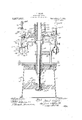
Figure 1 is a cross sectional viewof a iotarv can capper constructed in accordance with my invnntion7 the section being taken on the line `1--1 of Fig.` 2, looking in the of the structure shown in Fig. 1 with parts removed and parts broken away; V
Fig..3 is a cross sectional view taken on the line 3-8 of Fig. 4, looking in thev direction of the arrows;
Fig. 4 is a similar view taken on the. line H of Fig. 3;
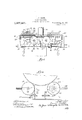
Fig. 5 is a top plan view of the discharge conveyer and chute;
Fig. 6 is a view in side elevation of the parts shown in Fig. 5;
Fig. 7 is a similar view showing in detail a portion r4of Fig. 5;
Fig. 8 is a side elevation with parts in section showing rthe transmission mechanism; Fig.` 9 is a top plan view of the capper with parts removed; and
Fig. 10 is a side elevation with parts re-A moved`r taken from the front of Fie'. 9.
Referring to the drawings, centrally mounted on a supporting base 11 is an upright shaft 12 having non-rotatably secured thereto a step bearing 13 on which rests a central 'chambered column 13.2L so as to be rotatable about the shaft.
The shaft 12 carrying the central column may be raised ory lowered to adjust the cap-k ping parts to cans of various heights by means of inter-meshing bevel gears 14 and 15, a collar 15?L on the latter being in screwthreaded engagement with the shaft, gear 14 being turned by a shaft 14a having a squareend for an operating crank, but the yshaftis made non-rotatable by means` of a is secured a pin 19 the other endk of which' is. secured to a large gear 20 on which is secured a table 21 for the cans. It will` be seen that rotation of the gear 20 will carry with it the table Q1 and the central column 13a. This lrotation. of the gear 20 is derived from a pinion 2:2 (Fig. S) with which it meshes, mounted on a shaft 23 journaled in a bearing 2i; on the supporting base 11, and having also, a bearingin a bracket 25. This bracket 25 is loosely mountedon a pin 26 on the base 11'in alineinent with shaft 23 to give the bracket a swivel connection. It issecured in any. position by meansvof pins 26a passing through flanges onthe bracket and base. The bracket has bearings E27 and 28 for a horizontaldrive shaft 29 having mounted thereon a bevel pinion 30 meshing with a bevel gear 31 on the end of the shaft 23. Rotatable on and slidable along the As will be apparent, when the driving pulley is in clutching engagement with the "drum` 33 its power is transmitted to the pinion 22 which drives the table and central column, via the shaft 29, gears 30, 31 and shaft 23. y
The capper may be set up'practically irrespective ofthe position of the main line shafting as the bracket 25 may be swiveled about its pivotal l,axis to present the drive pulley 32l at any angle necessary.
Referring again to Fig. i, the shaft 12 has ixedlyA secured thereto, near the top "thereof, a chambe'red member 35, radiating 'arms 35a of which carry segmental gear 36 for causing rotation of the cappingstcels as hereinafter described. Depending from ythe arms 35a are braclrets 35b whifi support a cam track 37 having a normal surface and twocam surfaces 37a, 37b, on which travel rollers 38 on lifting arms 39, the inner ends of which are ypivotally supported on' a shoulder formed on the collar 40 of a spider 41, said collar being secured to the central column 13a to rotate therewith, the spiderhaving a ring 42secured thereto, said -ring being connected to and supporting a second ring bearing 42n by means of rods 42b (Fig. 9) extending between the rings 42 and' j 42a, said rings providing bearings for steel supporting sleeves 43wherebythe latter are v' carried with the rotation of the ,other parts and, at the same time, are vertically slidable to place the capping steels in and out of contact with the cans, as hereinafter described.
Slidably embraced by the steel supporting sleeves 43 are vent rods 43n which are topped by. yweights 43blto cause them to descend byr gravity into contact with` the cans, `as herejinafter set forth, engagement of the `weights 5o with ring bearing 42L limiting such movef ment., l A, InY order that the capping steels may be rotated during the soldering process, each -vsteel supporting -sleeve 43 has mounted thereon a `pinion 44'. meshing withy the stationary segmental gear 36 as the sleeves are driven past the latter by the rotation of 'the central column. vDepending from theV pinions 44 are collars 45 bearing on the lift` mg arms 39 so that th'esteels may be raised t l or lowered according to theiposition of the .l
lifting arm ,rollers 38 on the cam track 37 '.ass hereinafter described.' l ssociated with each capping :steel is a fire box 46. The back part of these-fire boXes is formed by a channeled ring coinposed of a plurality of segmental castins 48 (Fig. 2) secured together in any suitab e manner. This ring may ber one circular piece but it is more practicable to cast it in three or four parts. The upper andlower ribs of these channeled castings 48 are pro= vided with apertures 49, 50 for the passage through the fire boxes of the capping steels 51, which are suspended from the sleeves 43 75 by yokes 51a, and bushings 51b embracing the sleeves 43 and resting on the capping steels so as to extend through the upper opening 49. The fire boxes are completed by front caps 52 having upper and lower 80 openings 53, 54 forthe steels and bushings corresponding with the apertures 49 and 50,
` and front air inlets 54a. These caps 52 are secured to the rear channeled segmentsy 48 by means of hooks 55 which engage corre- 85 spending` lugsformed on the latter, Fuel for the fire boxes is sup lied at a main port 57 opening into a ciainber 58 formed by the stationary memberf35. lt passes thencethrough ports 59 opening into v90 the interior of the central column, down theV latter to an enlarged chamber 60 communi- .eating with which are a plurality of pipes V6l leadin to the re boxes 46, one pipe for 'each fire 0X. To regulate the fuel supply 95 each pipe 61 has a valve 61a operated by aV valve handle 62 extending out far enough to be readily accessible.
Referring y,to Figs. 2, 3 and 4, the mechanism for feedingand discharging the cans will now be described. As already set forth v the large table gear 20 is drivenby pinion 22 which derives its power from the'main drive shaft 29. Meshing with this gear 2O is a Oear 63 mounted on a shaft 64 which is 105 ljournaled in a bearing 65 and has secured whichk carries the cans toward the table, the
chain being provided with spaced lugs 76 for engaging each can. y
Also meshing with table gear 20 to be driven thereby is a gear 77 on a shaft 78 journaled in bearing 79 and carrying at its 4upper end a feeding star-*sweep 80.
, Contiguous to the rotating table`21 is a stationary table 81 rwhicheXtends outwardly beneath the feeding and discharging sweep-k ers. Secured to this table is a bracket 82 carrying arcuate guides 83 and 84 substann ltially concentric with the feed and discharge sweeps respectively', the inner .endsl 86 of 130 o which extend well over the rotating table 21. To aid in properly positioning the cans,
i a centering guide 87 yis located across the its shaft y78 so that it be timed with relation to the position of the cans. The
sweep itself is loose on the shaft and screws 88 ig. 3) `tliieaded in a bifurcated lug 89 on a collar 90 which is fast on the shaft 78 bear on a lug v91 formed on the sweep, thus forming a driif'ing connection between sweep and shaft such that the former may be adjusted to properly time its movement with respect to thev cans.
Similar means are provided for adjusting discharge sweep 69 and sprocket 74.
Extending from adjacent the disczharge sweep 69 is a discharge table 92 supported atit's outer end by legs' 93'. A stub shaft 9st journaled in a bearingl bracket 95 secured to `the leg 93 carries a sprocket 96 for driving ythe discharge conveyer 97 on which are spaced lugs "for `engiigin'g the cans, the inner end of the conveyer traveling in an i idler sprocket 97h. kThis discharge conveyer extends away from thetable a substantial `distance and is substantially in `alinement with the feeding conveyer.'y To drive the sprocket 96 onlthe shaft'9lis also a bevelgear 98 meshing witha ,similar gear 99 on the end of the shaft 68`which is rotated as above set forth. The cans are deflected from the conveyer 97 bya chute 100 with which is associated anY adjustable guide member 101.
In order to adjust the timing of the discharge conveyer its driving gear 98 is itself loose upony shaft 94, a collar 102 fast on the which fits in a square socket 108 'supported j `by a leg 93 and is engaged at its end by a threaded `member `1f08a operated by a hand wheel 109. Itwill be apparent that rotation of the hand wheel will ,move the idler sprocket outwardly or allowing it to nieve l inwardly to ,tighten or loosen the chain.
To insure the proper engagement of the steel `rotating 1pinions 449 with segmental gear 36 when they first come in contact with the teeth thereof, a geared segment r110 is j pivoted at the `end of a `long arm to the frame of the gear 36, at 111. This geared 5Uy segment 110 is in a plane higher than the plane of gear 36 because at the point where j the steel pinioiismeet these gears the former are raised somewhat as'will hereinafter anpear. Thetwo segments overlap slightly, the
teeth being in verticaly alinement throughout such overlap, as shown in Fig. 10.' A block 112 pivotally mounted on the gear 36 has an aperture tlierethrough on which slides a rod 113 the other end of which is pivotally secured to the arin of the geared segment 110. coiled spring 114: surrounding said rod bears against the block 112 and against a lnut 115 on the rod thereby tending to press the geared segment 110 outwardly, but so as to permit it to give when engaged by the piiiions 414, the function of which hereinafter appears t The opei`aticn,"in general, is such thatthe cans with caps in place are brought up to the cappei' by an endless conveyer, thence they are swept onto a rotating table over which is suspended a plurality ofcapping 'steels and vent rods which travel therewith,
ineans being provided whereby the cans are spaced and centered so thateach one comes directly beneath a capping steel. As the apparatus rotates the soldering process takes place and the cans are finally swept from the table onto a second endless conveyer which carries theni away in spaced relation, in a course in alinement with that in which they were fed to the apparatus.
In more detail the operation is as follows: It will be apparent that the motionof substantially all of the parts depends on the large table bearing gear 20. This gear derives its rotation from the power pulley 32, shafty 29, gears 30, 31, shaft and pinion 22 when the clutch is thrown in by lever 3a. As gear 20 rotates it obviously carries 100 table 21 with it and' by means of the pin '19 and arm 18 the central column 13a is son with the table by the spider 4t2 and the 105 lire boxes by their pipe connections with the central column.
rlhis large gear 20 also rotates the two smaller gears 77 and 63 with which it meshes.w The former of these drives the feeding star sweeper 80 through shaft 78; the latter drives the discharge star sweeper 69 through shaft 611 and by the pinion 66 on the same shaft gears 67 and the shaft 68 are driven, the latter driving the feeding conveyer chain through spiral gears 71, 72, shaft 73 and sprocket 7 4, and the discharging conveyer chain through gears 99, 98, shaft 911 and sprocket 96.
Considering the clutch thrown in and the parts moving as above described cans are fed to the conveyer 75 in such a manner that they are engaged by the lugs 76 of the conveyer and carried up to the star sweeper 80 in spaced relation. The latter member, 125 in connection with the guide 83 causes the cans tobe deflected from the conveyer, across the stationary table `81 onto the rotating table 21, the guide 87 aiding in centering the cans so they will take the proper position under the capping steels. As each can takes its proper' place the corresponding capping steel and vent rod drop by gravity into capping` position, thevent rod holding the cap in place and the heated steel, which is rotated lon its own axis due to ythe pinion y44 running over the gear 36, performing the soldering operation. The parts remain in this position for about one third of their revolution.V Then the roller 38 of the lifting arm strikes ythe cam surface 37a of thecam track 37 and the arm is raised thereby rais- ,ing the sleeve 43 vby its engagement with the collar 45 to llift the capping steel o ut of contact withthe can cap. As there is now no necessity for rotation of the steel on its own f axis the teeth of gear 36 do not extend beyond this point.y 'Ihe vent rod remainsin contact with the cap to prevent it from moving while the solder cools, during .approximatelyl another third of the revolution. Furtherjtravel brings the roller4 38 to the 1 n higher ycam surface 371 thus causing the lifty drop by is applied.
jters." A y this point At the same timea fresh can is taking its y place, and the roller 38 descending from the cam surface to normal levelon the track 37 allows the capping steel and vent rod to gravityto the cap, and the above operation continues. In the above descriptionthe course of only one can with its corv responding steel, vent rod, and lifting arm has been traced. It will be apparent, howkever oneafter the other is identical, l the whole Aprocess being continuous as long as power `'In order that the steel-revolving pinions `44 shallmesh properlyk with the fixed gear I provide the spring-pressed pivoted gearedv 110 which each pinion rst encounthe steel supporting sleeves at have not completely descended to lnormal level, this segment is in a plane above that of gear 36 and overlaps the latter, the
segment teeth where this overlap occurs being 1n vertical alinement. Segment 110 forms in effect a resilient continuation of gear 36. If
Yto
It ywill be seen that the cans `must take vdefinite spaced, lpositions on 'the rotating table in order to come vdirectly under the steels. If it happens that the armsv of the sweeper 80 and the, can: engaging lugs 76 of the feed conveyer are not in proper timed relation with each, other or with the steels to attain such end, thesweep may beadjusted on its shaft by means of the screws 38 to attain ythe proper timed relation. Similar adjustmentmay be made with respect to thedrive sprocket 74 of the feed conveyer. Likewise the dischargesweep and the `drive pinion of the ydischarge conveyer are adjustable in the same manner so that proper timedv relation may be attained between the cans on the table, the arms of the discharge vsweeper and the discharge conveyery lugs. A y
In continuously operating rotary can cappers', not only `must the cans take definite` positions on therotary table, but it is necessary that theybe conveyed upto the table in spaced relation in lorder that they may pass the fluxingv and cap-dropping devices yin proper order and for the action of the feed Aand discharge sweep. Likewise they must be conveyed away from the cap'per in spaced relation for the action of the venthole tipper andnumber stamper. Ifa single conveyer serves for both feeding and discharging, it is difficult to adjust the parts so that'the conveyer lugs will be in proper timed relation with both the feed and delivery sweeps. By providing separate conveyers independently adjustable, applicant has, made it possible to attain the most exact adjustment. y
Having described my invention, what I claim as new and desire to secure by Letters yPatent is:
1. In a can capper, the combination with a rotaryA table on which the cans take spaced relation, a conveyer for V,carrying the cans up to' said table in spaced relation,`a second conveyer for carrying the cans away from said table, means for deflecting the cans from the first named conveyer to the table, means for deflecting the cans yfrom the table to the second named conveyer, means for driving said table, conveyers -and deflecting means, rmeans for timing said first named conveyer anddeflecting means withpzrespect to each otherv and either withvrespe'ct to the stable, and independent means for timing said second named conveyer and deliecting means -with respect to each other and either with 'the teethv vof pinions 44, when they rst enrespect to the table. y
2. In a can capper, the combination with a central non-rotatable shaft, a sleeve rotat- ,ably mounted thereonpa plurality of cap-l Cil said shaft thereby to cause said sleeve to raise or lower said capping steels with respect to said table.
In a can capper, the combination with a rotary table for the cans, of means for rotating the same, a conveyer for carrying the cans up to said table, a sprocket for moving said conveyer rotatably adjustable on a shaft, means4 for driving said shaft and sprocket, a rotary sweep for deflecting the cans from said conveyer to said table rotatably adjustable on a shaft, means for driving said shaft, a second conveyer for carrying the cans away from said table, a second rotary sweep for deflecting the cans from the table to said second conveyer rotatably adjustable on a shaft, means for driving said shaft and sweep, a gear rotatably adjustable on a shaft, means for driving said' shaft and gear, and means for driving' said second conveyer from said gear.
fl. In a can capper, the combination with a plurality of capping steels, of lire boxes for housing said steels, said fire boxes comprising a plurality of arcuate members of less number than the number of steels, partially housing said steels, and a plurality of caps, one for each steel, for completing the housing.
5. In a can capper, the combination with a plurality of capping steels, of fire boxes for housing said' steels, said lire boxes comprising an arcuate channeled member having apertures in its upper and lower flanges for a plurality of said steels, a plurality of caps one'for each steel having apertures corresponding to said first named apertures, and means for securing said caps to said channeled member.
6. In a can capper, the combination with a plurality of capping steels arranged in a ring, of lire boxes for housing said steels, said fire boxes comprising a plurality of arcuate channeled members substantially less than the number of said steels secured together to form a channeled ring partially housing said steels, and a plurality of caps, one for each steel secured to said arcuate members to complete the housing, there being a channel leading from one steel to another completely around the ring.
7,. A can capping machine comprising a non-rotating vertical shaft, a gear having a hub portion having a bore through which said shaft extends, said gear being nonrotatably mounted on said shaft, a plurality of capping steels, means for causing said steels to move in a circular pathabout said shaft, pinions associated with said steels and meshing with said gear, and means for supplying fuel adjacent said steels including a passage in said hub portion.
8, A can capping machine comprising a non-rotating vertical shaft, a gear having a hub portion having a bore through which said shaft extends, said gear being nonrotatably mounted on said shaft, a plurality ofy capping steels, means for causing said steels to move in a circular path about said shaft comprising a sleeve rotatable about said shaft, pinions associated with said steels and meshing with` said gear, means for sup-l plying fuel adjacent said steels including a passage in said hub portion, and a passage in said sleeve in communication with said first passage.
9. A can capping machine comprising a non-rotating' vertical shaft, a gear having a hub portion having a bore through which said `shaft extends, said gear being nonrotatably mounted on said shaft, a plurality of capping steels, means for causing said steels to move in a circular path about said shaft comprising a sleeve rotatable about said shaft, pinions associated with said steels and meshing with said gear, a casing in which said steels are located supported by said sleeve, and means for supplying fuel to said casing comprising a passage in said hub portion, and a passage in said sleeve in communication with said first passage.
In witness whereof, I have hereunto subscribed my name in the presence of two wit- JAMES P. HAIGHT.
' nesses.
J. B. HART.
Copies or this `patent may 'be obtained for five cents each, by addressing the Commissioner of Patents. Washington, D. C.
Priority Applications (1)
| Application Number | Priority Date | Filing Date | Title |
|---|---|---|---|
| US86507114A US1237897A (en) | 1914-10-05 | 1914-10-05 | Rotary can-capper. |
Applications Claiming Priority (1)
| Application Number | Priority Date | Filing Date | Title |
|---|---|---|---|
| US86507114A US1237897A (en) | 1914-10-05 | 1914-10-05 | Rotary can-capper. |
Publications (1)
| Publication Number | Publication Date |
|---|---|
| US1237897A true US1237897A (en) | 1917-08-21 |
Family
ID=3305714
Family Applications (1)
| Application Number | Title | Priority Date | Filing Date |
|---|---|---|---|
| US86507114A Expired - Lifetime US1237897A (en) | 1914-10-05 | 1914-10-05 | Rotary can-capper. |
Country Status (1)
| Country | Link |
|---|---|
| US (1) | US1237897A (en) |
-
1914
- 1914-10-05 US US86507114A patent/US1237897A/en not_active Expired - Lifetime
Similar Documents
| Publication | Publication Date | Title |
|---|---|---|
| US1073067A (en) | Can-filling machine. | |
| US2500465A (en) | Filling machine drive | |
| US1237897A (en) | Rotary can-capper. | |
| US2103158A (en) | Bottle filling machine | |
| US2517532A (en) | Dispensing machine for paper cups and the like | |
| US1023074A (en) | Feed mechanism for bottling-machines. | |
| US931434A (en) | Device for feeding cans to operating mechanisms. | |
| US1652419A (en) | Conveyer | |
| US1673236A (en) | Topping mechanism for filled-can-closing machines | |
| US1349837A (en) | Double-seamer | |
| US1133401A (en) | Tube-bending machine. | |
| US1043066A (en) | Bottle-handling apparatus. | |
| US1104751A (en) | Double-seaming machine. | |
| US1100333A (en) | Canning-machine. | |
| US450276A (en) | winters | |
| US908373A (en) | Can-capping machine. | |
| US1415403A (en) | Sand-blast apparatus | |
| USRE25962E (en) | Container closing machinery | |
| US1811162A (en) | Can end lining machine | |
| US1436746A (en) | Bean-snipping machine | |
| US515283A (en) | Can-filling machine | |
| US1745589A (en) | Bottle-cap-assembling machine | |
| US1972841A (en) | Can packing device | |
| US1507166A (en) | Process and apparatus for sealing under vacuum | |
| US1196174A (en) | tayloe |