US1237862A - Primer for gas-engines. - Google Patents
Primer for gas-engines. Download PDFInfo
- Publication number
- US1237862A US1237862A US3205015A US3205015A US1237862A US 1237862 A US1237862 A US 1237862A US 3205015 A US3205015 A US 3205015A US 3205015 A US3205015 A US 3205015A US 1237862 A US1237862 A US 1237862A
- Authority
- US
- United States
- Prior art keywords
- casing
- primer
- gas
- supply pipe
- coil
- Prior art date
- Legal status (The legal status is an assumption and is not a legal conclusion. Google has not performed a legal analysis and makes no representation as to the accuracy of the status listed.)
- Expired - Lifetime
Links
Images

Classifications
-
- F—MECHANICAL ENGINEERING; LIGHTING; HEATING; WEAPONS; BLASTING
- F02—COMBUSTION ENGINES; HOT-GAS OR COMBUSTION-PRODUCT ENGINE PLANTS
- F02M—SUPPLYING COMBUSTION ENGINES IN GENERAL WITH COMBUSTIBLE MIXTURES OR CONSTITUENTS THEREOF
- F02M15/00—Carburettors with heating, cooling or thermal insulating means for combustion-air, fuel, or fuel-air mixture
- F02M15/02—Carburettors with heating, cooling or thermal insulating means for combustion-air, fuel, or fuel-air mixture with heating means, e.g. to combat ice-formation
- F02M15/04—Carburettors with heating, cooling or thermal insulating means for combustion-air, fuel, or fuel-air mixture with heating means, e.g. to combat ice-formation the means being electrical
-
- A—HUMAN NECESSITIES
- A61—MEDICAL OR VETERINARY SCIENCE; HYGIENE
- A61M—DEVICES FOR INTRODUCING MEDIA INTO, OR ONTO, THE BODY; DEVICES FOR TRANSDUCING BODY MEDIA OR FOR TAKING MEDIA FROM THE BODY; DEVICES FOR PRODUCING OR ENDING SLEEP OR STUPOR
- A61M16/00—Devices for influencing the respiratory system of patients by gas treatment, e.g. mouth-to-mouth respiration; Tracheal tubes
- A61M16/10—Preparation of respiratory gases or vapours
- A61M16/14—Preparation of respiratory gases or vapours by mixing different fluids, one of them being in a liquid phase
- A61M16/16—Devices to humidify the respiration air
Definitions
- EWIL B ERT BINTLIFF PLAINFIELD, NEW JERSEY, ASSIGNOR F ONE-HALF TO I v I ALLEN B. LAING, 0F PLAINFIELD, NEW JERSEY.
- My present inven- 'tion relates to an apparatus for heating a liquid hydrocarbon fuel to a point of vaporization, if necessary,-so that the sameis properly heated when introduced into a'mixing chamber to be combined with 'the air before supplying the same to the engine cylinder in starting the engine, and is so constructed that it may be employed at all times in the continuous running of a gas engine to properly vaporize kerosene or other relatively low grade hydrocarbons whenit is not possible or. convenient to employ gasolene.
- ilTheiprimer made in accordance with my invention is preferably heated electrically and may be attached directly to the engine manifold or associated with the carbureter in such a manner that the vaporized liquid, at the necessary temperature, may pass therefrom to the chamber wherein it is mixed with the air beforeentering the engine cylinders.
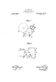
- FIG. 1 is a diagrammatic plan and partial cross section of a gas engine apparatus as applied to an automobile in which my improved primer is includedi
- Fig.--2 is a central longitudinal section illustrating the primer made in accordance with my invention
- 'F ig. ,3 is a, similar view showing a modifiedform of the invention.
- Fig. 4 is also a central, longitudinal cross section illustrating the use of the primer when combined with a carburetor
- Figs. 5 and 6 are, respectively, a plan and partial cross section and a side elevation of may be suitably secured in a manifold or other part of the engine apparatus,
- the casing is provided with a cover 13, which, as illustrated, is provided with a flange adapted to fit Within the open end of the casing and to be secured in position therein by a set screw 14, or otherwise.
- the cover 13 is provided with a boss 15 fitted with a cap 16 for a purpose to be hereinafter indicated.
- I employ a coil pipe 17, which is part of the fuel supply pipe lead-- ing from the source of liquid fuel to: the carbureter or the manifold.
- One end of the coil, as'indicated at 18 is set in a conical recess in the boss 15 in such a manner that a pipe connection may be made thereto, while the opposite end 19 of the coilpipe 17 extends through a bore provided therefor in a connection 12, as indicated at 19, and may be connected to any' place at which it is desired to discharge the vaporized hydrocarbon.
- I may employ a heat coil 20 surrounding the coil pipe 17 with the convolutions of the heat coil-20 spaced from each' other and also separated from the coil pipe by layers of insulating or other material 21.
- One end of the heat coil 20 is connected to a binding screw 22, secured in and in sulated from the casing 10 in any suitable manner and provided with a thumb nut 23 by which connections may be made with a circuit wire.
- the opposite end of the heat coil 20 is grounded in the casing 10 by being connected thereto, asindicated at 24. 2
- the primer as hereinbefore described, may be directly connect ed to the engine manifold 25 by a coupling 35.
- the supply pipe 34 extends between the T valve 33 and the intake side of the primer, and as indicated in Fig. 2, this pipe passes through the cap 16 and through a filling piece which is forced to place by turning the cap to position, in order to make a suitable joint between the ends of the pipes.
- a battery 36 or othersource of electricity
- one side of the battery is grounded in the frame of the machine by a lead wire 37 while the other side of the battery is connected by a line 38 to one side of a switch 39, the other side of the switch being connected by a line 40 to the binding screw 22, mounted inthe casing of the primer, as hereinbefore described.
- control valve 31' of the carbureter may be closed and the T valve 33 open and the switch 39 so placed as to put the heat coil in the battery circuit when it is desired to start the engine, and as will be understood a rheostat or other current controlling device may be employed, if desired, in the battery circuit to regulate the heat generated by the coil 20.
- the carbureter valve 31' may be opened and the T valve 33 closed so as to utilize the carbureter 31, but if necessary, in theuse of kerosene or other similar low grade hydrocarbon fuels, the rimer may be used for the vaporization thereof in the continued running of the engine, in order to supply to the engine cylinders 41 an eflicient ex losive mixture.
- the casing 10 is provided with a cover 42 of insulating material, and centrally the cover is fitted with a metal sleeve, a portion of which passes through the cover and is secured in place therein by the nut 44 and the flange 45.
- the outer end of the sleeve is adapted to receive a cap 46, through which the supply pipe 34 extends, and within which the pipe is connected to a bushing 47, there being a washer employed in order to make the necessary tight joint between ends of the pipes when the cap 46 is turned down to place.
- the cap 46 also acts as a binding nut for a contact piece 49 secured to the end of a lead wire 50, the contact piece being secured in place between the inner end of the cap and the adjacent face of the shoulder 45, in order to connect the coiled portion 51 of the supply pipe in an electric circuit, the oppo site end of this coiled portion of the su ply pipe being grounded in the other end 0 the casing, as lndicated at 52.
- the primer casing may be made an integral part of the carbureter, being placed between the float valve casing 53 and the casing 54 of a mixin chamber 55.
- the in ct end of the coiled portion of the supply pipe is secured in the float valve casing and is rovided with a spring controlled ball va ve 56 to prevent the vaporized hydrocarbon from returning to the float valve chamber, which, as illustrated in this figure, is provided with an inlet connection 57 ada ted to be secured to the pipe leading from t e supply tank.
- the opposite or discharge end of the coiled portion of the supply pipe lying within the primer casing is connected in a bore provided in a wall 60 extending across the mixing chamber 55, the wall 60 being provided with a discharge nozzle 61 for the vaporized liquid fuel, and the outlet passage from the nozzle being controlled by a needle valve 62, or any other similar and suitable device.
- the mixing chamber may be provided with a check valve 63 placed below the wall 60 and with a throttle valve 64 placed above the wall 60.
- the primer made in accordance with my present invention may also be employed in conjunction with the carbureter in such a manner that it may be used'independently thereof.
- the inlet end of the coiled supply pipe in the primer is connected to the control valve 65 leadingjo" the float valve chamber, while the opposite supply pipe within the space inclosed by the said casing and having one end in communication with the supply tank, andthe other in communication with the mixing chamber,
- a primer'for gas engines comprising a casing providing an entirely inclosed chamber, a supply ipe having closely coiled convolutions withi iithe said chamber, one end of the supply pipe being connected to a source of liquid supply, and the other to the inlet to a gas engine cylinder, an elec tric heating coil immediately surrounding the convolutions of the supply pipe, and a terminal secured in the casing and to which one end of the heating coil is connected, the other end of the electric heating coil being grounded in the casing.
- a primer for gas engines comprising a mixing chamber, a supply tank, a casing intermediate of and integral with the said supply tank and mixing chamber, a helically coiled supply pipe within the chamber inclosed by the said casing and havingone end Copies ofthis patent may be obtained for five cents each, by addressing the in communication with the supply tank and the other end in communication with the mixing chamber, and an electric heating coil surrounding and wound immediately upon the convolutions of the supply pipe, the helically coiled supply pipe being open ended and the same with the electric heating coil being placed within the chamber in the casing so as to leave space for circulation between the same and the walls of the said casing.
- a supply tank a mixing chamber, a casing intermediate of and integral with the said supply tank and mixing chamber, a helically coiled supply pipe within the said casing with one end in communication with the supply tank and the other in communication with the mixing chamber, an electric heating coil surrounding the convolutions of the said supply pipe within the said casing, aspring actuated valve for permitting the liquid fuel to flow from the supply tank to the supply pipe and preventing its return, and a needle valve for regulating the admission of the liquid fuel from the said supply pipe to the said mixing chamber.
- WILBERT T BIN TLIFF.
Description
W. T. BINTLIFF.
PRIMER FOR GAS ENGINES.
APPLICATION FILED JUNE 4, \915.
GASOLENE TANK INVENTOR Patented Aug. 21, 1917.
2 SHEETSSHEET 1.
WITNESSES W. T. BINTLIFF.
PRIMER FOR GAS ENGINES.
APPLICATION FILED JUNE 4. ms.
1,237,862 Patented Aug. 21, 1917.
2 SHEETS SHEET 2- W/TNESSES INVENTOR 6 i/ wvm d I ATTO UNITED STATES PATENT OFFICE.
EWIL B ERT BINTLIFF, PLAINFIELD, NEW JERSEY, ASSIGNOR F ONE-HALF TO I v I ALLEN B. LAING, 0F PLAINFIELD, NEW JERSEY.
'. To all whom it may concern Be known that I, WILBERT T. BINTLIFF,
. acitizen of the United States, residing at Plainfield, in the county of. Union and State of New Jersey, haveinvented an Improvement in Primers for Gas-Engines, of which the following is a specification.
- In order to obtain an efficient explosive mixture for use in gas engines, it is necessary to combine the gas or vaporized hydro- I carbon with air in predetermined quantities,
and it is generally known that cold gas and cold air will not commingle properly to from an efficient explosive mixture. It-is for this reason that difliculty is often experienced in starting gas engines.
I am aware that heretofore various de vices have been provided for the preliminary heating ofveither the gas or the air, or
both the gas and the air. My present inven- 'tion, however, relates to an apparatus for heating a liquid hydrocarbon fuel to a point of vaporization, if necessary,-so that the sameis properly heated when introduced into a'mixing chamber to be combined with 'the air before supplying the same to the engine cylinder in starting the engine, and is so constructed that it may be employed at all times in the continuous running of a gas engine to properly vaporize kerosene or other relatively low grade hydrocarbons whenit is not possible or. convenient to employ gasolene.
ilTheiprimer made in accordance with my invention is preferably heated electrically and may be attached directly to the engine manifold or associated with the carbureter in such a manner that the vaporized liquid, at the necessary temperature, may pass therefrom to the chamber wherein it is mixed with the air beforeentering the engine cylinders.
The construction of my improved primer will be hereinafter more particularly described in conjunction with the accompanying drawings, in which Figure 1 is a diagrammatic plan and partial cross section of a gas engine apparatus as applied to an automobile in which my improved primer is includedi --Fig.--2 is a central longitudinal section illustrating the primer made in accordance with my invention; I
'F ig. ,3: is a, similar view showing a modifiedform of the invention.
- 'PRIMERIFOR GAS-ENGINES.
Specification of Letters Patent. Patented Aug, 21, 1917, Application filed June 4, 1915. Serial No. 32,050.
Fig. 4 is also a central, longitudinal cross section illustrating the use of the primer when combined with a carburetor, and
Figs. 5 and 6 are, respectively, a plan and partial cross section and a side elevation of may be suitably secured in a manifold or other part of the engine apparatus, At the opposite end, the casing is provided with a cover 13, which, as illustrated, is provided with a flange adapted to fit Within the open end of the casing and to be secured in position therein by a set screw 14, or otherwise. The cover 13 is provided with a boss 15 fitted with a cap 16 for a purpose to be hereinafter indicated.
Within the casing, I employ a coil pipe 17, which is part of the fuel supply pipe lead-- ing from the source of liquid fuel to: the carbureter or the manifold. One end of the coil, as'indicated at 18 is set in a conical recess in the boss 15 in such a manner that a pipe connection may be made thereto, while the opposite end 19 of the coilpipe 17 extends through a bore provided therefor in a connection 12, as indicated at 19, and may be connected to any' place at which it is desired to discharge the vaporized hydrocarbon.
As indicated in this figure, I may employ a heat coil 20 surrounding the coil pipe 17 with the convolutions of the heat coil-20 spaced from each' other and also separated from the coil pipe by layers of insulating or other material 21. Y
One end of the heat coil 20 is connected to a binding screw 22, secured in and in sulated from the casing 10 in any suitable manner and provided with a thumb nut 23 by which connections may be made with a circuit wire. The opposite end of the heat coil 20 is grounded in the casing 10 by being connected thereto, asindicated at 24. 2 Referring to Fig, 1, the primer, as hereinbefore described, may be directly connect ed to the engine manifold 25 by a coupling 35. The supply pipe 34 extends between the T valve 33 and the intake side of the primer, and as indicated in Fig. 2, this pipe passes through the cap 16 and through a filling piece which is forced to place by turning the cap to position, in order to make a suitable joint between the ends of the pipes.
As also indicated in Fig. 1, it is necessary to employ a battery 36, or othersource of electricity, and one side of the battery is grounded in the frame of the machine by a lead wire 37 while the other side of the battery is connected by a line 38 to one side of a switch 39, the other side of the switch being connected by a line 40 to the binding screw 22, mounted inthe casing of the primer, as hereinbefore described.
It will now be apparent that in the use of this apparatus, the control valve 31' of the carbureter may be closed and the T valve 33 open and the switch 39 so placed as to put the heat coil in the battery circuit when it is desired to start the engine, and as will be understood a rheostat or other current controlling device may be employed, if desired, in the battery circuit to regulate the heat generated by the coil 20.
In the use of gasolene or other similar fuel, after the engine has been properly started, the carbureter valve 31' may be opened and the T valve 33 closed so as to utilize the carbureter 31, but if necessary, in theuse of kerosene or other similar low grade hydrocarbon fuels, the rimer may be used for the vaporization thereof in the continued running of the engine, in order to supply to the engine cylinders 41 an eflicient ex losive mixture.
By re erence to Fig. 3, it will be seen that instead of employing the heat coil 20, as shown and described in connection with the form of invention shown in Fig. 2, I may construct the primer in such a manner as to heat the coil supply pi e itself, in order to vaporize the liquid fuei.
In this construction, the casing 10 is provided with a cover 42 of insulating material, and centrally the cover is fitted with a metal sleeve, a portion of which passes through the cover and is secured in place therein by the nut 44 and the flange 45. The outer end of the sleeve is adapted to receive a cap 46, through which the supply pipe 34 extends, and within which the pipe is connected to a bushing 47, there being a washer employed in order to make the necessary tight joint between ends of the pipes when the cap 46 is turned down to place.
The cap 46 also acts as a binding nut for a contact piece 49 secured to the end of a lead wire 50, the contact piece being secured in place between the inner end of the cap and the adjacent face of the shoulder 45, in order to connect the coiled portion 51 of the supply pipe in an electric circuit, the oppo site end of this coiled portion of the su ply pipe being grounded in the other end 0 the casing, as lndicated at 52.
The use of this form of the invention is precisely similar to that hereinbefore described in connection with the construction illustrated in Fig. 2.
Referring to Fig. 4, it will be seen that the primer casing may be made an integral part of the carbureter, being placed between the float valve casing 53 and the casing 54 of a mixin chamber 55. In this construction, the in ct end of the coiled portion of the supply pipe is secured in the float valve casing and is rovided with a spring controlled ball va ve 56 to prevent the vaporized hydrocarbon from returning to the float valve chamber, which, as illustrated in this figure, is provided with an inlet connection 57 ada ted to be secured to the pipe leading from t e supply tank.
The opposite or discharge end of the coiled portion of the supply pipe lying within the primer casing is connected in a bore provided in a wall 60 extending across the mixing chamber 55, the wall 60 being provided with a discharge nozzle 61 for the vaporized liquid fuel, and the outlet passage from the nozzle being controlled by a needle valve 62, or any other similar and suitable device.
As is customary, the mixing chamber may be provided with a check valve 63 placed below the wall 60 and with a throttle valve 64 placed above the wall 60.
Referring to Figs. 5 and 6, it will be see-n that the primer made in accordance with my present invention may also be employed in conjunction with the carbureter in such a manner that it may be used'independently thereof. In this construction, the inlet end of the coiled supply pipe in the primer is connected to the control valve 65 leadingjo" the float valve chamber, while the opposite supply pipe within the space inclosed by the said casing and having one end in communication with the supply tank, andthe other in communication with the mixing chamber,
and a heating coil immediately surrounding the convolutions of the supply pipe, the said supply pipe beingopen ended and the same together with the heating coil placed in the space within the casing so as to provide for a circulation between the same and the wallsof the casing;
2. A primer'for gas engines comprising a casing providing an entirely inclosed chamber, a supply ipe having closely coiled convolutions withi iithe said chamber, one end of the supply pipe being connected to a source of liquid supply, and the other to the inlet to a gas engine cylinder, an elec tric heating coil immediately surrounding the convolutions of the supply pipe, and a terminal secured in the casing and to which one end of the heating coil is connected, the other end of the electric heating coil being grounded in the casing.
3. A primer for gas engines comprising a mixing chamber, a supply tank, a casing intermediate of and integral with the said supply tank and mixing chamber, a helically coiled supply pipe within the chamber inclosed by the said casing and havingone end Copies ofthis patent may be obtained for five cents each, by addressing the in communication with the supply tank and the other end in communication with the mixing chamber, and an electric heating coil surrounding and wound immediately upon the convolutions of the supply pipe, the helically coiled supply pipe being open ended and the same with the electric heating coil being placed within the chamber in the casing so as to leave space for circulation between the same and the walls of the said casing.
4. In an apparatus of the class described and in combination, a supply tank, a mixing chamber, a casing intermediate of and integral with the said supply tank and mixing chamber, a helically coiled supply pipe within the said casing with one end in communication with the supply tank and the other in communication with the mixing chamber, an electric heating coil surrounding the convolutions of the said supply pipe within the said casing, aspring actuated valve for permitting the liquid fuel to flow from the supply tank to the supply pipe and preventing its return, and a needle valve for regulating the admission of the liquid fuel from the said supply pipe to the said mixing chamber.
Signed by me this th day of April, 1915.
WILBERT T. BIN TLIFF.
Commissioner of Patent;
Washington, D. 0.
Priority Applications (2)
| Application Number | Priority Date | Filing Date | Title |
|---|---|---|---|
| US3205015A US1237862A (en) | 1915-06-04 | 1915-06-04 | Primer for gas-engines. |
| US131185A US1286512A (en) | 1915-06-04 | 1916-11-14 | Gas-engine primer. |
Applications Claiming Priority (1)
| Application Number | Priority Date | Filing Date | Title |
|---|---|---|---|
| US3205015A US1237862A (en) | 1915-06-04 | 1915-06-04 | Primer for gas-engines. |
Publications (1)
| Publication Number | Publication Date |
|---|---|
| US1237862A true US1237862A (en) | 1917-08-21 |
Family
ID=3305679
Family Applications (1)
| Application Number | Title | Priority Date | Filing Date |
|---|---|---|---|
| US3205015A Expired - Lifetime US1237862A (en) | 1915-06-04 | 1915-06-04 | Primer for gas-engines. |
Country Status (1)
| Country | Link |
|---|---|
| US (1) | US1237862A (en) |
Cited By (15)
| Publication number | Priority date | Publication date | Assignee | Title |
|---|---|---|---|---|
| US2479888A (en) * | 1943-07-06 | 1949-08-23 | Reaction Motors Inc | Controlling system for reaction motors |
| US3055750A (en) * | 1959-10-20 | 1962-09-25 | Carolis Julius J De | Cold weather starting apparatus for diesel engines |
| US3377464A (en) * | 1965-06-21 | 1968-04-09 | Trans Continental Electronics | Electric resistance heating and insulating system for elongated pipes |
| US3423569A (en) * | 1962-04-05 | 1969-01-21 | Wiegand Co Edwin L | Electric air heater for automatic choke |
| US3443059A (en) * | 1965-10-11 | 1969-05-06 | Lockwood Tech | Hand tool for applying hot melt adhesives and the like |
| US4207277A (en) * | 1977-10-19 | 1980-06-10 | Toyota Jidosha Kogyo Kabushiki Kaisha | Float chamber means for a carburetor |
| US4397287A (en) * | 1979-09-17 | 1983-08-09 | Jocelyn Pierard | Method and apparatus for liquefying and/or heating a fluid |
| US4517926A (en) * | 1982-04-19 | 1985-05-21 | Optimizer, Limited | Device for improving fuel efficiency and method of use therefor |
| US4635608A (en) * | 1981-08-28 | 1987-01-13 | Carroll Bruce I | Alcohol fuel conversion apparatus for internal combustion engines |
| US4711223A (en) * | 1981-08-28 | 1987-12-08 | Carroll Bruce I | Alcohol fuel conversion apparatus |
| US5769272A (en) * | 1995-01-25 | 1998-06-23 | Massena; Leo | Removable cartridges for a glue gun system |
| US5881924A (en) * | 1997-01-17 | 1999-03-16 | Uniplast, Inc. | Feeder handler for a hot glue gun |
| US5881923A (en) * | 1997-01-17 | 1999-03-16 | Uniplast, Inc | Removable cartridge for a hot glue gun |
| US5881912A (en) * | 1997-01-17 | 1999-03-16 | Uniplast, Inc. | Glue gun with removable barrel |
| US20050279848A1 (en) * | 2004-06-21 | 2005-12-22 | Parker Randall D | Engine pre-heater system |
-
1915
- 1915-06-04 US US3205015A patent/US1237862A/en not_active Expired - Lifetime
Cited By (17)
| Publication number | Priority date | Publication date | Assignee | Title |
|---|---|---|---|---|
| US2479888A (en) * | 1943-07-06 | 1949-08-23 | Reaction Motors Inc | Controlling system for reaction motors |
| US3055750A (en) * | 1959-10-20 | 1962-09-25 | Carolis Julius J De | Cold weather starting apparatus for diesel engines |
| US3423569A (en) * | 1962-04-05 | 1969-01-21 | Wiegand Co Edwin L | Electric air heater for automatic choke |
| US3377464A (en) * | 1965-06-21 | 1968-04-09 | Trans Continental Electronics | Electric resistance heating and insulating system for elongated pipes |
| US3443059A (en) * | 1965-10-11 | 1969-05-06 | Lockwood Tech | Hand tool for applying hot melt adhesives and the like |
| US4207277A (en) * | 1977-10-19 | 1980-06-10 | Toyota Jidosha Kogyo Kabushiki Kaisha | Float chamber means for a carburetor |
| US4397287A (en) * | 1979-09-17 | 1983-08-09 | Jocelyn Pierard | Method and apparatus for liquefying and/or heating a fluid |
| US4635608A (en) * | 1981-08-28 | 1987-01-13 | Carroll Bruce I | Alcohol fuel conversion apparatus for internal combustion engines |
| US4711223A (en) * | 1981-08-28 | 1987-12-08 | Carroll Bruce I | Alcohol fuel conversion apparatus |
| US4517926A (en) * | 1982-04-19 | 1985-05-21 | Optimizer, Limited | Device for improving fuel efficiency and method of use therefor |
| US5769272A (en) * | 1995-01-25 | 1998-06-23 | Massena; Leo | Removable cartridges for a glue gun system |
| US5779103A (en) * | 1995-01-25 | 1998-07-14 | Massena; Leonard | Glue gun system with removable cartridges |
| US5881924A (en) * | 1997-01-17 | 1999-03-16 | Uniplast, Inc. | Feeder handler for a hot glue gun |
| US5881923A (en) * | 1997-01-17 | 1999-03-16 | Uniplast, Inc | Removable cartridge for a hot glue gun |
| US5881912A (en) * | 1997-01-17 | 1999-03-16 | Uniplast, Inc. | Glue gun with removable barrel |
| US20050279848A1 (en) * | 2004-06-21 | 2005-12-22 | Parker Randall D | Engine pre-heater system |
| US7059537B2 (en) | 2004-06-21 | 2006-06-13 | Parker Randall D | Engine pre-heater system |
Similar Documents
| Publication | Publication Date | Title |
|---|---|---|
| US1237862A (en) | Primer for gas-engines. | |
| US1456018A (en) | Internal-combustion engine | |
| US1223124A (en) | Vaporizer and igniter for internal-combustion engines. | |
| US1361503A (en) | Internal-combustion engine | |
| US1136845A (en) | Electric vaporizer. | |
| US1326000A (en) | Albebt schmid | |
| US1060042A (en) | Vaporizer for internal-combustion engines. | |
| US1293456A (en) | Vaporizer. | |
| US904203A (en) | Fuel-heater for explosive-engines. | |
| US1133845A (en) | Explosive-engine. | |
| US1006244A (en) | Explosive-engine. | |
| US1118237A (en) | Gaseous-fuel mixer. | |
| US1286512A (en) | Gas-engine primer. | |
| US1374519A (en) | Carbon-remover | |
| US1325998A (en) | Albert schmid | |
| US1230909A (en) | Internal-combustion engine. | |
| US1739818A (en) | Carburetor | |
| US1211087A (en) | Means for converting kerosene-oil into explosive gas for internal-combustion engines. | |
| US1242258A (en) | Means for starting internal-combustion engines. | |
| US1424898A (en) | Gas heater and vaporizer | |
| US1386238A (en) | Carbureter | |
| US1276169A (en) | Carbureter. | |
| US1215027A (en) | Fuel-vaporizer for internal-combustion engines. | |
| US1220039A (en) | Kerosene-vaporizer for automobile-engines. | |
| US1454929A (en) | Heating primer |