US1237805A - Solder-strip-coating machine. - Google Patents
Solder-strip-coating machine. Download PDFInfo
- Publication number
- US1237805A US1237805A US84611814A US1914846118A US1237805A US 1237805 A US1237805 A US 1237805A US 84611814 A US84611814 A US 84611814A US 1914846118 A US1914846118 A US 1914846118A US 1237805 A US1237805 A US 1237805A
- Authority
- US
- United States
- Prior art keywords
- solder
- sheet
- machine
- strip
- rolls
- Prior art date
- Legal status (The legal status is an assumption and is not a legal conclusion. Google has not performed a legal analysis and makes no representation as to the accuracy of the status listed.)
- Expired - Lifetime
Links
- 238000000576 coating method Methods 0.000 title description 11
- 239000011248 coating agent Substances 0.000 title description 10
- 229910000679 solder Inorganic materials 0.000 description 71
- 230000004907 flux Effects 0.000 description 6
- 238000010276 construction Methods 0.000 description 3
- 238000010438 heat treatment Methods 0.000 description 2
- 239000002184 metal Substances 0.000 description 2
- 229910052751 metal Inorganic materials 0.000 description 2
- 229910000746 Structural steel Inorganic materials 0.000 description 1
- 150000001768 cations Chemical class 0.000 description 1
Images


Classifications
-
- B—PERFORMING OPERATIONS; TRANSPORTING
- B31—MAKING ARTICLES OF PAPER, CARDBOARD OR MATERIAL WORKED IN A MANNER ANALOGOUS TO PAPER; WORKING PAPER, CARDBOARD OR MATERIAL WORKED IN A MANNER ANALOGOUS TO PAPER
- B31B—MAKING CONTAINERS OF PAPER, CARDBOARD OR MATERIAL WORKED IN A MANNER ANALOGOUS TO PAPER
- B31B50/00—Making rigid or semi-rigid containers, e.g. boxes or cartons
- B31B50/60—Uniting opposed surfaces or edges; Taping
- B31B50/62—Uniting opposed surfaces or edges; Taping by adhesives
-
- H—ELECTRICITY
- H01—ELECTRIC ELEMENTS
- H01B—CABLES; CONDUCTORS; INSULATORS; SELECTION OF MATERIALS FOR THEIR CONDUCTIVE, INSULATING OR DIELECTRIC PROPERTIES
- H01B13/00—Apparatus or processes specially adapted for manufacturing conductors or cables
- H01B13/34—Apparatus or processes specially adapted for manufacturing conductors or cables for marking conductors or cables
- H01B13/341—Apparatus or processes specially adapted for manufacturing conductors or cables for marking conductors or cables using marking wheels, discs, rollers, drums, balls or belts
Definitions
- the invention relates to new and useful improvements in solder applyinghdevices and more particularly to devices for applying solder tometal in sheet form prior to the same being cut into blanks to be utilized informing can bodies, or. the like.
- An object of the invention isto provide an apparatus of the above character wherein the sheets may be fed one after another through the apparatus and each sheetjprovided with a solder strip positioned on the sheet so that when the sheet is out into suitable shaped blanks and formed into can bodies the solder onthe sheet may beutilized for joining the edges of the body blanks;
- a further object of the inventionisto provide ail-apparatus of the above-character wherein the sheets being coated with a strip of solder may be turned over and coated on each side thereof.
- a still further Object of the invention is to provide an apparatus of the, above character wvliicli may be quickly adjusted to adapt thesame for sheets of different widths for the. makingof can bodies of different sizes.
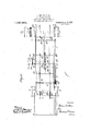
- Figure 1 is a side view of an apparatus embodying my improvements
- Fig. 2 is a plan View of the same.
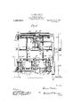
- Fig. 3 is a sectional-view onthe line 33 ofFig.l.
- Fig. 4 is an end view of the machine.
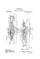
- Y Fig.5 is an enlarged view showing a longitudinal section through the center part of themachine.
- Fig. 6 is a perspective viewshowing a sheet of metal coated with solder'strips.
- Fig. 7 shows a blank cut from said sheet
- Fig. 8 shows theblank formed into a can Q i/w d. v
- Fig. 9 is a detail view of the stopfor limiting the movements of the arm which sup-. ports the pressure rolls.
- v Q i .”Iheinve'n'tion consists generally-in providing a supporting frame on .which are mounted suitable traveling carrying devices which take the sheets to be coated one after another and carry the same through the machine. These traveling devices may be in the form of endless chains, or other suitable means may be used.
- a solder applyingde 1 vice located beneath theplane of travel of the sheet and this solderapplying.device is preferably in the form; of a soldertrough in which are mounted rolls which engage the lower face of the sheet and handuip the solder from the troughto the sheet, These rolls all travel in the same path onthe sheet so that each roll forms a solder coating 3 on the sheet and these coatings of solder build up to form a solder strip.
- nism is a fluxing device which may be of similar construction to the solder applying devices. Pressure rolls engage "the upper face of they sheet and hold the same in contact with the fluXing roll and the solder. applying rolls.
- the machine is preferably so constructedthat the sheet travels from one end thereof to the other vvhereit' is turned over or reversed and travels backagain to the receiving end of the machine. .Asithe sheet returns to the receiving end of the ma:
- solder strip applying devices operate I to coat. or apply solder strips to the under face of the sheet so that as the sheet travels through the machine both sides thereof will be supplied with solder strips.
- the apparatus or. machine herein shown and describedl may be usedjfor various purposes, it is especially adapted for applying, solder strips to sheets of metal which are subsequently cut to form body blanks for can bodies.
- a solder strip located centrallythereof. and extending fromend to end of the sheet.
- Theusheet S is provided with a solder strip acentrallythereof on one face.
- This sheet is also provided with threesoldermstrips b, 0, and d, on the other face thereof.
- the strip 0 extends longitudinally of the sheet centrally of the sheet, and the strips 72 and (Z are locatedat the outer edgesthereof.
- sheet thus coated maybe cut on the broken lines as indicated in Fig. 6 and. will thus form eight body blanks, each of which is indicated at '8. formed into a can body, as shown-inl ig. 8, the solder strips a, b, and are brought together. in such a waythat they may be utilized for joining the edges of the blank and thus closing the side seam;
- the cutting of the sheet. as above suggested is solely for the purpose of making clear one purpose of the invention.
- ratus or machine consists offa mainframe which comprises standards 1, 1 and 2-, 2-.
- Tli ese' standards are joined by a connecting I-beai'n 3.
- A' c'rossbar e extends also between the standards at each end of the machine.
- a shaft 5' is suitably niethu in the standards lfl, while a shaft 6is journale d'at the opposite end of the machine in the standards 2, 2.
- the shaft 6 carries a gear wheel 7 which meshes with a gear wheel 8 on acountershaft which in turn 'is driven by a suitable belt wheel Q.
- Mounted on the shaft 6 is 'a'pair of sprocket wheelslO,
- solder applyingdevices consistsof a solder trough 17 which is suitably connected to the beam 14;. This "solder trough has heating cdlnp'art ment18 underneath the same, which may be I. Heatd bya 8111155516 a' pipe 19. Located athe solder bath ar assets or shafts o,
- bracket 30 In the bracket 30 is a shaft 32 which is likewise threaded and engages threaded nuts at the other end of the guide bars 27 and 28. These guide bars are so disposed relative to the supporting chains 12, 12 that the side edges of the sheet are supported and guided by the guide bars.
- Flux isapplied to the sheet prior to the engagement of the solder rolls therewith by flux rolls 33.
- These flux rolls are carried by suitable shafts and rotate in a flux bath 3 1 which is also mounted on the supporting beam 14.
- the flux rolls 33 and the solder rolls 20 may be positively driven by a suitable chain 35 which runs over gears 36 carried by each of the shafts or supports for the rolls and also over idle gears 37 as shown in dotted lines in Fig. 5.
- This chain 35 is driven from a gear 38 carried by a shaft 39 whichis j ournaled in thebeam 1 1.
- the shaft 39 is also j ournaled in a side standard 40 and it"may be driven by a suitable belt 11.
- 1 A. pressure roll 12 coeperates to hold the sheets in contact with the fluxing rolls 33.
- This pressure roll 12 is carried by an arm 43 which is pivotally mounted on the supporting bar 26. Suitable stops may be provided for limiting the downward movements of the arms 25 and 13 when there is no sheet in the machine so as to hold these pressure rolls from contacting with the fluxin rolls and solder rolls.
- the fluxing bath is indicated at 47 and in said bath are fluxing rolls carried by shafts which support gears atv their outer ends.
- the solder bath is indicated at 4,8 and is provided with solder rolls 49 which are mounted. on suitable shafts, each of which carries a gear at its outer end.
- An endless chain 50 runs over the gears for positively driving each of the rolls.
- This chain 50 cotiperateswith a sprocket gear 51 on a shaft 52, and the shaft 52 is journaled in the longitudinal beams and also in the standard 40.
- a belt Wheel 53 on the shaft 52 is actuated by a belt 54 from a belt wheel 55 on the shaft 39.
- the guide rails 27. and. 57 are joined by a U-shaped guide rail 58, while the guide rails 28 and 56 are joined by all-shaped guide rail 59. .
- the guide rails: 58 and 59 are shaped to conform to the travel of. the chains about the sprocket wheels 10. , The sheet whichis to be carried along bythe endless chains 12, 12 will be caused by the guide rails 58' and 59 to follow the travel of the chain, that is reverse. their direction of travel and pass back to the receiving end of the machine, and as they reverse their travel, the sheets are turned over.
- each'beam 44, 45 and .46 there is a bath associated with each'beam 44, 45 and .46 and these solder applying devicesare disposed so as to apply a strip of solder at the center of the sheet and at each edge of the sheet.
- the guides 56, 57 are cut away to permit the solder rolls to pass through and contact with the sheet.
- the sheets may be stacked on the table 22 and placed one at a time on the traveling chains and as the clips carried by the chains engage the sheet, said sheets will be caused to travel with the chain.
- the sheet will pass underneath the pressure roll and a line of flux applied to the under face thereof, after which the sheet passes underneath the second set of pressure rolls and a strip of solder will be coated on the under face of the sheet.
- This return travel of the sheets presents the same to the three solder strip coating devices which engage the under face of the sheet and form a solder strip at the center of the sheet and at each edge of the sheet.
- the sheet When the sheet reaches the front end of the machine, it may be stacked on a suitable truck, indicated at 60.
- solder baths at thelower part of the machine are similar in construction and; have been given like numbers.
- Each solder bath is heated by a suitable gas pipe 61 which is connected to a suitable source of supply. It will be understood that other means may be utilized for heating the solder bath, if
- the shaft 31 carries a hand wheel 62 and also asprocket wheel which is connected by a sprocket chain 63 with a sprocket wheel on the shaft 32.
- the turning of the shaft 31 by the wheel 62 will impart a like rotary movement to the shaft 32 and as these shafts are rotated the guide rails 27 and 28 will be moved an equal distance toward or from the center of. the machine.
- the supporting beams 44 and 46 rest on theI-beams 3. These longitudinal beams are not, however, attached to the Lbeams, while the longitudinal beam 45 is bolted to the I-beams 3 by bolts 45
- a shaft 64 is journaled in the beam 45us0 as to rotate freely therein but isheld from endwise movement in the beam. This shaft is formed with right and left hand threads which engage threaded lugs on the longitudinal beams 45 and 46. likewise mounted in the longitudinal beam 45
- a second shaft 65 is and has right and left hand threads engaging threaded'lugs on the beams 44 and 46.
- the shaft 64 is provided with a hand wheel 66 and also with a sprocket chain 67 which runs over a sprocket wheel on the shaft 65.
- the sprocket chain 67 will impart a like rotation to the shaft 65 and this will move the outside solder applying devices toward and from the center solder applying device.
- the guide rails 56 and 57 are supported by the solder baths and will be moved therewith.
- the outer arms 49' for supporting the pressure rolls 49 are freely pivoted on a fixed shaft or supporting rod 49. from endwise movement by suitable adjustable collars so that, when the solder baths are adjusted, the arms may be shifted on their supporting shaft or red so as to bring the pressure rolls directly above the solder rolls.
- a solder strip coating machine in-' cluding in combination a traveling support for the sheets to be coated, mechanism for applying a strip of solder to the under face of the sheet centrally thereof, means for reversing the sheet and mechanism for applying a strip of solder to the opposite face of the sheet centrally thereof and at the edges of the'sheet.
- a solder strip coating machine including in combination a traveling support for conveying the sheet through the machine for reversing the sheet and returning the same through the machine, solder applying mechanism for applying a strip of solder to the under face of the sheet as it passes through the machine in one direction and mechanism for applying a strip of solder to the other face of the sheet on its return movement through the machine.
- a solder coating machine including in combination an endless conveyer for supporting the sheets and carrying the same through the machine, reversing the sheets and returning the same through the machine, solder applying devices including spaced solder rolls for applying a strip of solder centrally'of'the sheet and solder applying mechanism operating upon the sheet in its return movement through the machine for applying a single strip of solder to the sheet centrally thereof, and a strip at each edge of the sheet on the face of the sheet opposite to the first applied coating strips.
Description
E. NORTON, DECIL,
L. E. NORTON, EXECUTRIX. SOLDER STRIP comma MACHINE.
Patented Aug. 21, 1917.
5' SHEETS--SHEET 1.
E. NORTON, DECD.
L- E. NORTON, EXECUTRIX. SOLDER STRIP COATING MACHINE.
APPLlCATIGN FILED JUNE 19, I914- Patented Ailg' 21, 1917.
5 SHEETS-'SHEETY 2.
, I l l l I I I l P (I 5 SHEETS-SHEET 3.
Patented Aug. 21, 1 917 E. NORTON, DECD.
L. E. NORTON. EXECUTRIX.
SOLDER SIRIP COATING MACHINE.
- APPLI CATION FILED JUNE 19. 1914.
0 I U 0% 9d g mm m A m W ..i w I. W M 6 5 LT 1.11M! c E. NORTON. DECD. L. auomou. exec'unux. SOLDER STRIP comma MACHINE;
APPLICATION FILED JUNE 9, I914. v
Patented'Aug. 21, 1917.
5' SHEETS-SHEET 4.
E. NORTON. DEC'D L. E. women. EXECUTRIXL SOLDER STRIP COATING MACHINE.
APPLICATION FILED 1UNE19, I914- Patented Aug. 21, 1917.
5SHEETS-SHEET 5.
EDWIN nonromor raenrwnsr, BERMUDA; Il oY E. NORTON EXECUTRIX orsAIn EDWIN NORTON, iJEonAsEn soLnnn-srrtir-ooarme- MACHINE To all whom it may concern:
v vious and will in Be it known that I, EDWIN NonroN, a citizen of the United States, residing at Paget WVest, Bermuda, have invented certain new and useful Improvements in Solder- Strip-Coating Machines, of which the following is a description, reference being had to the accompanying drawing and to the figures of reference marked thereon.
The invention relates to new and useful improvements in solder applyinghdevices and more particularly to devices for applying solder tometal in sheet form prior to the same being cut into blanks to be utilized informing can bodies, or. the like.
7 An object of the invention isto provide an apparatus of the above character wherein the sheets may be fed one after another through the apparatus and each sheetjprovided with a solder strip positioned on the sheet so that when the sheet is out into suitable shaped blanks and formed into can bodies the solder onthe sheet may beutilized for joining the edges of the body blanks;
A further object of the inventionisto provide ail-apparatus of the above-character wherein the sheets being coated with a strip of solder may be turned over and coated on each side thereof.
A still further Object of the invention is to provide an apparatus of the, above character wvliicli may be quickly adjusted to adapt thesame for sheets of different widths for the. makingof can bodies of different sizes.
These and other obj ects will in partbe ob partjbe hereinafter more fullydisclosed. I l v v In the drawings, which show by wayof illustration oneembodiment of the invention,
Figure 1 is a side view of an apparatus embodying my improvements;
Fig. 2 is a plan View of the same. i
Fig. 3 is a sectional-view onthe line 33 ofFig.l.
Fig. 4 is an end view of the machine.
Y Fig.5 is an enlarged view showing a longitudinal section through the center part of themachine.
Fig. 6 is a perspective viewshowing a sheet of metal coated with solder'strips.
Fig. 7 shows a blank cut from said sheet Fig. 8 shows theblank formed into a can Q i/w d. v
Specification of Letters Patent. i
Patented Aug. 21, 1917.
Ap lication fiIed June 19, 1914. serial ii eeaus.
. Fig. 9 isa detail view of the stopfor limiting the movements of the arm which sup-. ports the pressure rolls. v Q i ."Iheinve'n'tion consists generally-in providing a supporting frame on .which are mounted suitable traveling carrying devices which take the sheets to be coated one after another and carry the same through the machine. These traveling devices may be in the form of endless chains, or other suitable means may be used. A solder applyingde 1 viceis located beneath theplane of travel of the sheet and this solderapplying.device is preferably in the form; of a soldertrough in which are mounted rolls which engage the lower face of the sheet and handuip the solder from the troughto the sheet, These rolls all travel in the same path onthe sheet so that each roll forms a solder coating 3 on the sheet and these coatings of solder build up to form a solder strip. r i
nism is a fluxing device which may be of similar construction to the solder applying devices. Pressure rolls engage "the upper face of they sheet and hold the same in contact with the fluXing roll and the solder. applying rolls. The machine is preferably so constructedthat the sheet travels from one end thereof to the other vvhereit' is turned over or reversed and travels backagain to the receiving end of the machine. .Asithe sheet returns to the receiving end of the ma:
In advance of the solder applying .mechachine, solder strip applying devices operate I to coat. or apply solder strips to the under face of the sheet so that as the sheet travels through the machine both sides thereof will be supplied with solder strips. v 1
While the apparatus or. machine herein shown and describedlmay be usedjfor various purposes, it is especially adapted for applying, solder strips to sheets of metal which are subsequently cut to form body blanks for can bodies. To this end, it is desirable to provide the sheet with a solder strip located centrallythereof. and extending fromend to end of the sheet. Such a sheetis shownin Fig. 6 of the drawings. Theusheet S is provided with a solder strip acentrallythereof on one face. This sheet is also provided with threesoldermstrips b, 0, and d, on the other face thereof. The strip 0 extends longitudinally of the sheet centrally of the sheet, and the strips 72 and (Z are locatedat the outer edgesthereof.
sheet thus coated maybe cut on the broken lines as indicated in Fig. 6 and. will thus form eight body blanks, each of which is indicated at '8. formed into a can body, as shown-inl ig. 8, the solder strips a, b, and are brought together. in such a waythat they may be utilized for joining the edges of the blank and thus closing the side seam; The cutting of the sheet. as above suggested is solely for the purpose of making clear one purpose of the invention.
Referring in detail ratus or machine consists offa mainframe which comprises standards 1, 1 and 2-, 2-.
Tli ese' standards are joined by a connecting I-beai'n 3. A' c'rossbar e extends also between the standards at each end of the machine. A shaft 5' is suitably jeumaleu in the standards lfl, while a shaft 6is journale d'at the opposite end of the machine in the standards 2, 2. The shaft 6 carries a gear wheel 7 which meshes with a gear wheel 8 on acountershaft which in turn 'is driven by a suitable belt wheel Q. Mounted on the shaft 6 is 'a'pair of sprocket wheelslO,
I0. Also mounted on the sh'aft 5 at the Ilal'ed support f t sachets thereof (in the shafts oand l6} respectively. The journal support- 15 is held from endwise [movement onfthej sha'ft by collars 16. This beam supp'b ts'the ap ly ng devices n we solderapplying devices. The solder applyingdevices consistsof a solder trough 17 which is suitably connected to the beam 14;. This "solder trough has heating cdlnp'art ment18 underneath the same, which may be I. Heatd bya 8111155516 a' pipe 19. Located athe solder bath ar assets or shafts o,
I05; -Ql s 'pfbiided w th a h a n upor ooatin roll 21. The solder in the solderlbath 1 is kept in molten condition an ,ithe ls unni g. n he so e e beco e coatedwith the solder and carrythe $511151? u'p'wf h h ,j h I Thesheets tobe coated are placed on the endless chains 12, 12 a't the receiving end of theinachine. At this end o'fthe machine 60 i re ey be ui pQ ti s p cke' e 22. io'r the stack of sheets. OI'ieby one the sheets are laid. fonthe shag-as which any spaced sip- 23. These [dupegag the end of the sheet so the sheet travels withthe "hain; These "chains are me When this bodyblank 8 is H to the apparatus for applying solder strips to a sheet,-sai'd appa sheets over the top of the solder trough 17 so that thesolder rolls may contact with the lower face of the sheet. These rolls extend slightly above the top of the solder bath. As a means. forholding the sheet firmly in contact with the solder rolls, I have provided pressure rolls 2 1. These rolls are guide bars 27 and 28 have threaded nuts attaohed thereto which coiiperate with this threaded shaft 31. In the bracket 30 is a shaft 32 which is likewise threaded and engages threaded nuts at the other end of the guide bars 27 and 28. These guide bars are so disposed relative to the supporting chains 12, 12 that the side edges of the sheet are supported and guided by the guide bars.
Flux isapplied to the sheet prior to the engagement of the solder rolls therewith by flux rolls 33. These flux rolls are carried by suitable shafts and rotate in a flux bath 3 1 which is also mounted on the supporting beam 14. The flux rolls 33 and the solder rolls 20 may be positively driven by a suitable chain 35 which runs over gears 36 carried by each of the shafts or supports for the rolls and also over idle gears 37 as shown in dotted lines in Fig. 5. This chain 35 is driven from a gear 38 carried by a shaft 39 whichis j ournaled in thebeam 1 1. The shaft 39 is also j ournaled in a side standard 40 and it"may be driven by a suitable belt 11. 1 A. pressure roll 12 coeperates to hold the sheets in contact with the fluxing rolls 33. This pressure roll 12 is carried by an arm 43 which is pivotally mounted on the supporting bar 26. Suitable stops may be provided for limiting the downward movements of the arms 25 and 13 when there is no sheet in the machine so as to hold these pressure rolls from contacting with the fluxin rolls and solder rolls.
n Fig. 9 of the drawings, I have shown the shaft '26 which is fixed against rotation as formed with a slot 26. A pin 26 carried by the arm 25 extends into the slot and striking against the end of the slot serves as a stop for limiting the downward movement of the arm 25. A similar pin and slot construction also serves as a "limiting stop for the arm 43.
At the lower part of the machine there are three beams 14:, 45 and 16 which extend fromend to end of the machine and are supported by I-beams 3. Mounted on'each of these longitudinal beams is a fiuxing bath and'solder bath: similar to the ones above described. The fluxing bath is indicated at 47 and in said bath are fluxing rolls carried by shafts which support gears atv their outer ends. The solder bath is indicated at 4,8 and is provided with solder rolls 49 which are mounted. on suitable shafts, each of which carries a gear at its outer end. An endless chain 50 runs over the gears for positively driving each of the rolls. This chain 50 cotiperateswith a sprocket gear 51 on a shaft 52, and the shaft 52 is journaled in the longitudinal beams and also in the standard 40. A belt Wheel 53 on the shaft 52 is actuated by a belt 54 from a belt wheel 55 on the shaft 39. At the lower part of the machine there are also angle iron guide rails 56 and 57. Tlhese guide rails are supported by the solder bath and rest on cross bars 4. i
The guide rails 27. and. 57 are joined by a U-shaped guide rail 58, while the guide rails 28 and 56 are joined by all-shaped guide rail 59. .The guide rails: 58 and 59 are shaped to conform to the travel of. the chains about the sprocket wheels 10. ,The sheet whichis to be carried along bythe endless chains 12, 12 will be caused by the guide rails 58' and 59 to follow the travel of the chain, that is reverse. their direction of travel and pass back to the receiving end of the machine, and as they reverse their travel, the sheets are turned over. As above noted, there is a bath associated with each'beam 44, 45 and .46 and these solder applying devicesare disposed so as to apply a strip of solder at the center of the sheet and at each edge of the sheet. The guides 56, 57 are cut away to permit the solder rolls to pass through and contact with the sheet.
.From the above description, it will be apparent that the sheets may be stacked on the table 22 and placed one at a time on the traveling chains and as the clips carried by the chains engage the sheet, said sheets will be caused to travel with the chain. The sheet will pass underneath the pressure roll and a line of flux applied to the under face thereof, after which the sheet passes underneath the second set of pressure rolls and a strip of solder will be coated on the under face of the sheet. As the sheet continues its travel following the endless chain, it will be turned over and caused to return to the front end of the machine. This return travel of the sheets presents the same to the three solder strip coating devices which engage the under face of the sheet and form a solder strip at the center of the sheet and at each edge of the sheet. When the sheet reaches the front end of the machine, it may be stacked on a suitable truck, indicated at 60.
The solder baths at thelower part of the machine are similar in construction and; have been given like numbers. Each solder bath is heated by a suitable gas pipe 61 which is connected to a suitable source of supply. It will be understood that other means may be utilized for heating the solder bath, if
and 32, as above described. The shaft 31 carries a hand wheel 62 and also asprocket wheel which is connected by a sprocket chain 63 with a sprocket wheel on the shaft 32. The turning of the shaft 31 by the wheel 62 will impart a like rotary movement to the shaft 32 and as these shafts are rotated the guide rails 27 and 28 will be moved an equal distance toward or from the center of. the machine.
. The supporting beams 44 and 46, as above noted, rest on theI-beams 3. These longitudinal beams are not, however, attached to the Lbeams, while the longitudinal beam 45 is bolted to the I-beams 3 by bolts 45 A shaft 64 is journaled in the beam 45us0 as to rotate freely therein but isheld from endwise movement in the beam. This shaft is formed with right and left hand threads which engage threaded lugs on the longitudinal beams 45 and 46. likewise mounted in the longitudinal beam 45 A second shaft 65 is and has right and left hand threads engaging threaded'lugs on the beams 44 and 46. The shaft 64 is provided with a hand wheel 66 and also with a sprocket chain 67 which runs over a sprocket wheel on the shaft 65. By turning the shaft 64 through the hand wheel 66, the sprocket chain 67 will impart a like rotation to the shaft 65 and this will move the outside solder applying devices toward and from the center solder applying device. The guide rails 56 and 57, as above noted, are supported by the solder baths and will be moved therewith. The outer arms 49' for supporting the pressure rolls 49 are freely pivoted on a fixed shaft or supporting rod 49. from endwise movement by suitable adjustable collars so that, when the solder baths are adjusted, the arms may be shifted on their supporting shaft or red so as to bring the pressure rolls directly above the solder rolls. The roll coiiperating with the flux- These arms are held I maylbe loosene'd and the sprocket wheels adjusted hand when the solder baths are shifted. It will thus be seen that I have provided meanswhereby the machine may bequickly adjusted for coating sheets of difie r ent Widths and without requiring any attention as to the locating of thesolder strip 'in'the center of the sheet as these adjustments are equal on each side of the center plane of the machine and the adjustin'g means itself determines the proper positioning of the parts adjusted.
-lVhi leZ-I have "described in detail an orgainifz ed mechanism for coating sheets, it 1 will" be understood that my invention is Y not-embodied'in the detail mechanism dis- (Elose'd but consists broadly in the arrangem'ent and operation of solder applying devices and conveying -means for presenting 3 the sheets thereto wherebythe sheets may 'bei'coa te'd with a strip of solder first on one face? and then on the other, which solder strips are disposed in a certain mined relation to the sheet.
,It is obvlous, therefore, that other devices predeter- .1119; in combination a traveling support for the sheets, mechanism for applying a strip *ofsolderto the under face of the sheet as fi t passe's through the machine, means for y an ' :(iiqpies of this patent may be obtained for reversingthe sheet and mechanism for apar Sh t- :plying'astrip of solder to theopposite side 2. A solder strip coating machine in-' cluding in combination a traveling support for the sheets to be coated, mechanism for applying a strip of solder to the under face of the sheet centrally thereof, means for reversing the sheet and mechanism for applying a strip of solder to the opposite face of the sheet centrally thereof and at the edges of the'sheet.
3. A solder strip coating machine including in combination a traveling support for conveying the sheet through the machine for reversing the sheet and returning the same through the machine, solder applying mechanism for applying a strip of solder to the under face of the sheet as it passes through the machine in one direction and mechanism for applying a strip of solder to the other face of the sheet on its return movement through the machine.
4:. A solder coating machine including in combination an endless conveyer for supporting the sheets and carrying the same through the machine, reversing the sheets and returning the same through the machine, solder applying devices including spaced solder rolls for applying a strip of solder centrally'of'the sheet and solder applying mechanism operating upon the sheet in its return movement through the machine for applying a single strip of solder to the sheet centrally thereof, and a strip at each edge of the sheet on the face of the sheet opposite to the first applied coating strips.
In testimony whereof, I aiiix my signature, in the presence of two witnesses.
' EDWIN NORTON.
Witnesses:
LUCY E. Non'ron, H. D. MOMILLAN.
five cents each,'by addressing the Commissioner of Patents,
Washington, D. 0;
Priority Applications (1)
| Application Number | Priority Date | Filing Date | Title |
|---|---|---|---|
| US84611814A US1237805A (en) | 1914-06-19 | 1914-06-19 | Solder-strip-coating machine. |
Applications Claiming Priority (1)
| Application Number | Priority Date | Filing Date | Title |
|---|---|---|---|
| US84611814A US1237805A (en) | 1914-06-19 | 1914-06-19 | Solder-strip-coating machine. |
Publications (1)
| Publication Number | Publication Date |
|---|---|
| US1237805A true US1237805A (en) | 1917-08-21 |
Family
ID=3305622
Family Applications (1)
| Application Number | Title | Priority Date | Filing Date |
|---|---|---|---|
| US84611814A Expired - Lifetime US1237805A (en) | 1914-06-19 | 1914-06-19 | Solder-strip-coating machine. |
Country Status (1)
| Country | Link |
|---|---|
| US (1) | US1237805A (en) |
Cited By (1)
| Publication number | Priority date | Publication date | Assignee | Title |
|---|---|---|---|---|
| US2923264A (en) * | 1954-04-21 | 1960-02-02 | American Can Co | Can body making and side seam soldering machine with seam aligning device and brake |
-
1914
- 1914-06-19 US US84611814A patent/US1237805A/en not_active Expired - Lifetime
Cited By (1)
| Publication number | Priority date | Publication date | Assignee | Title |
|---|---|---|---|---|
| US2923264A (en) * | 1954-04-21 | 1960-02-02 | American Can Co | Can body making and side seam soldering machine with seam aligning device and brake |
Similar Documents
| Publication | Publication Date | Title |
|---|---|---|
| KR940003658A (en) | A device for continuously joining and welding at least two sheets by a laser beam | |
| US1237805A (en) | Solder-strip-coating machine. | |
| US2198264A (en) | Apparatus for welding | |
| US3154665A (en) | Welding machine and method | |
| US3318749A (en) | Method and apparatus for laminating thin sheet material to relatively rigid base units | |
| US709864A (en) | Apparatus for edge-uniting veneers. | |
| US3251707A (en) | Method and apparatus for decorating glassware | |
| US2761487A (en) | Method and apparatus for making web covered spaced panels | |
| US1707712A (en) | Slide-box-shell machine | |
| US1096633A (en) | Box-folding machine. | |
| US2550159A (en) | Pipe handling gear | |
| US2668708A (en) | Transfer mechanism for sealing means | |
| US1581120A (en) | Sheet-delivery table | |
| US1410667A (en) | Method for handling prepared roofing | |
| US1348387A (en) | Art of making plaster-board | |
| US4438914A (en) | Cloth laying machine | |
| JPH05503910A (en) | Support frame for continuous conveying equipment | |
| US1465563A (en) | Apparatus for the manufacture of protected metal sheets | |
| CN205185398U (en) | A folding device for folding equipment is pasted to box | |
| US3591441A (en) | Band sealer | |
| US1871326A (en) | Arc welding machine | |
| US1476112A (en) | Conveyer | |
| US1338716A (en) | Soldering-machine | |
| US247745A (en) | Said s | |
| US234195A (en) | Herman miller |