US1237802A - Trimming mechanism. - Google Patents
Trimming mechanism. Download PDFInfo
- Publication number
- US1237802A US1237802A US78793513A US1913787935A US1237802A US 1237802 A US1237802 A US 1237802A US 78793513 A US78793513 A US 78793513A US 1913787935 A US1913787935 A US 1913787935A US 1237802 A US1237802 A US 1237802A
- Authority
- US
- United States
- Prior art keywords
- blade
- trimming
- stationary
- movable
- work support
- Prior art date
- Legal status (The legal status is an assumption and is not a legal conclusion. Google has not performed a legal analysis and makes no representation as to the accuracy of the status listed.)
- Expired - Lifetime
Links
- 238000009966 trimming Methods 0.000 title description 111
- 230000007246 mechanism Effects 0.000 title description 54
- 239000000463 material Substances 0.000 description 15
- 230000000149 penetrating effect Effects 0.000 description 13
- 238000009877 rendering Methods 0.000 description 12
- 238000009958 sewing Methods 0.000 description 8
- 238000010276 construction Methods 0.000 description 4
- 239000004744 fabric Substances 0.000 description 3
- 239000011435 rock Substances 0.000 description 3
- 210000003127 knee Anatomy 0.000 description 2
- 238000010008 shearing Methods 0.000 description 2
- 230000000881 depressing effect Effects 0.000 description 1
- 230000008774 maternal effect Effects 0.000 description 1
- MCYTYTUNNNZWOK-LCLOTLQISA-N penetratin Chemical compound C([C@H](NC(=O)[C@H](CC=1C2=CC=CC=C2NC=1)NC(=O)[C@H]([C@@H](C)CC)NC(=O)[C@H](CCCCN)NC(=O)[C@@H](NC(=O)[C@H](CCC(N)=O)NC(=O)[C@@H](N)CCCNC(N)=N)[C@@H](C)CC)C(=O)N[C@@H](CCC(N)=O)C(=O)N[C@@H](CC(N)=O)C(=O)N[C@@H](CCCNC(N)=N)C(=O)N[C@@H](CCCNC(N)=N)C(=O)N[C@@H](CCSC)C(=O)N[C@@H](CCCCN)C(=O)N[C@@H](CC=1C2=CC=CC=C2NC=1)C(=O)N[C@@H](CCCCN)C(=O)N[C@@H](CCCCN)C(N)=O)C1=CC=CC=C1 MCYTYTUNNNZWOK-LCLOTLQISA-N 0.000 description 1
- 108010043655 penetratin Proteins 0.000 description 1
- 108090000623 proteins and genes Proteins 0.000 description 1
- 230000000979 retarding effect Effects 0.000 description 1
Images

Classifications
-
- D—TEXTILES; PAPER
- D05—SEWING; EMBROIDERING; TUFTING
- D05B—SEWING
- D05B37/00—Devices incorporated in sewing machines for slitting, grooving, or cutting
- D05B37/04—Cutting devices
Definitions
- SHEETS-SHEET 3 JAMES R. Morrirrr, or GI-IIGAGO,
- the invention relates to new useful improvements in trimming mechanisms
- a further object of the invention is to provide .a trimmingmechanism, which includes a movable trimming member overhanging the work support so as to penetrate between superposed layersof material and trim certain of said layers only, with devices whereby the lower cooperating' trimming.
- the member may be shifted during the stitching operation to cause the material being cut to pass over said overhanging blade,- or shifted so as to permit said overhanging blade to become eltective to perform itscuttingaction'.
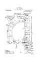
- FIG. 1 is a front elevation of a sewing I 1ectsabove and overhangs machine, with a portion of the worksupport removed, which embodies my lnventlon;
- Fig. 2 is an end View of themachine showreference marked An object 'mer. blade
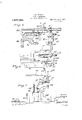
- Fig. 4 is a perspective view of the a: plate, the lower trimmer support, and the.
- Fig. ing the operatingmechanism for themov- 5 is a transverse sectional View showessreivoa'ro UNION sPEoIAnMAoninn able: trimming blade and the member for shifting the lower trimming blade;
- Fig. 6 is a plan View showing the trim ming mechanism and the devices for shiftmg the lower trimming member
- Fig. 7 isa front view. of the partsshown in Fi 6., b
- this trimming otherwise located relative to the stitching mechanism may tirely independent of erally in. providing a blade which cooperates with-a'ledger blade
- This ledger blade is tionary-that is,
- Theinvention consists gene r reciprocating trimmer p no movement in the normalcutting action of the blade on the fabric, it will bereferred to hereinafter as a fiXedor stationary bring mounted at the will of the operatorjand without stopping the stitching mechanism,
- blade f tionary blade above the range of action of the movable cutting blade, oler said movable cutting My invention is especially related to a trimming mechanism wherein the movable cutting blade is mounted and actuated by v and thereby ren-p bladeineflective;
- blade is formed with a forwardly pro ecting penetrating fixed This fixed or above noted, is 1 mounted" in afmovable carrier or support so that 1t may be raised and lowered and therebycause the material to eltherpass over the projecting "point; of the 'movable trimming blade or else all-ow'saidmovable' point to become effective to penetrate the vmaterial and the cutting blade to cut the material.
- the needle i-bar' is reciproc'a'tediby a-needlelever 6,-which is operated from the main shaft 7in the usualmanner.
- This feed rocker 13 is oscillated iby an arm 14: connected by a link. -15' to crank pin '16? on the'end of the main shaft-7.
- the feedbar is :raised' an dlowered 1 'tli e usualmanner.
- a movable trim- I kmin'gblade 17 Locatedlshghtly,an advanceof'the 'needles, (as shown in Fig. 5, is a movable trim- I kmin'gblade 17.
- blade ismountedon a supporting '18, located beneath the Work support, and said This movable trimming blade projects I above the work support and cuttingfed'ge will-cooperate with a 'fixed or which rests upon an eccentric stationary blade '19 to. perform :a shearing cut on the fabric.
- Said movable :eutting blade-' is' also provided with a penetrating pointin-"
- the bar :18 is preferably pivoted at QO-toi an operating-yoke 2 1, which, in turn, ispivoteclbto a link 22' attached at its other end toa'post or lug on the .bed plate.
- This yoke is provlded with bearing plates '23, 24: carried by thezm-ain'sh-aft A spring '25, see Fig.5,
- the fixed or stationaryblade 1:9 is mount ed in a support 27," Whl0ll is pivotally car ried by downwardly projecting lugs '28 I and, 29, as herein shown formed 'in'tegrah with the throat plateiSO of ithe sewing machine; Saidsupport 27: is free .to move on asupporting shaft 81.
- the throatplate is cut away so as to allow the supporting shaft and the upper face of the stationary blade 19 to rest'flush with the upper face of the throat plate "when the parts are positioned, as shownin Figs. 2, 4t and 5.
- This arm 42' is normally raised by a spring liisoasitohold theadjustable stud 34: away the knee shift, will more the stud 34- into contact with the arm'38 :and this willswing the support 27 on the -'.-shaft 31 and thus raise the innernend of the stationary blade 19, asshown, for example, in Fig. 3 of the drawings.
- the stud 34- By adjusting the stud 34-, the position to which lthis stationary member is raised unay be varied.
- the bearing 40 is provided with stops 44:, which limit the swing. of the rockshaft forfcontrolling the position of the stationary trimming blade.
- This stationary trimming blade 19 is detachably secured to the support27 therefor by a clamping plate 45,
- the blade is formed with inclined edges and the plate overlaps one of said inclined'edges.
- the trimming mechanism is effective for trimming
- the stationaryblade is in horizontaliposition, as show-n in Fig. t.
- the movable blade 17 reciprocating up and down. relative to said fixed or stationary blade, will cut the material passing underneath said movable blade by a downward shearing cutting action.
- This blade is so shaped that a plurality of layers of mate rial, if desired, may be pressed to. the cutting blade and the point will penetrate between the layers causing one ofthef-layers to pass ov-er said movable blade, While the other layer passes underneath the same and is out.
- the position of point e of the .movable blade varied-to setthe same for penetratin wbetween layers of material of a certain thick ness by shifting the bolt 26, which moves. relative to the actu atthe supporting bar 18 ing yoke for thetrimmer blade.
- the trimming mechanism is preferably located inadvance of the stitching mechanism, and whensodisposed an j edge of fabric may be trimmed and prepared for the stitching mechanism.
- the trimming mechanism is in advance of a tvvoneedle single thread carrymglooper stitching nechanisnna cut edge may be prepared and directed between the needles, and said out edge covered by the crossloops ofthe looper thread.
- a trimming mechanism including in combination a Work support, a reciprocat ing trimming blade, a cooperating normally stationary blade, and means for moving said stationary blade in a vertical plane above the cutting surface of the reciprocating trimming blade to render the cutting action ofthe reciprocating blade ineffective Withlgut stopping the action of said reciprocating lade.
- a trimming mechanism including a reciprocating trimmingblade, a cooperating normally stationary blade, and means for moving said stationary blade to renderthe cuttingaction. of the movable blade ineffective and automatic meansffor moving said stationary blade for rendering the movable blade effective When released by the operator, i l
- trimming 'mechanism including in combination a worksupport, a reciprocating trimmingblade mounted beneath theavork support,and projecting above and overhang ing said ork support, a normally station 5 ary triii'nning blade cooperating with said movableblade, and means for moving said stationary blade so as to direct the material over the top of the movable blade and there 1 by render the same ineffective.
- a trimming mechanism including in oo nbinationa Work support, a reciprocating trimming blade mounted beneath the Work support, and projecting above and overhangmg said Work support, a normally station- 5 ary trimming blade cooperating with said movableblade, and means for moving said stationary blade so as to direct the material over the top of the movable blade and thereby render the same ineffective, said means y for moving the stationary blade being under the control of the operator and shiftable ithout-stopping the reciprocations of the movable blade.
- a trimming mechanism including a 2 Worksupport, a reciprocating trimmer blade mounted beneath said Work support and proi ectmg above and overhanging the same, said movable blade. having a penetrating point, a normally stationary blade cooperat.
- a trimming mechanism including a work support, a reciprocating trimmer blade -1 :.-moimted beneath said work support and PIOIIGCtIHgELbOVQitlltl overhanging the same,
- saidwmovable blade havinga penetrating point, anormally stationary blade cooperating with said movable blade, and normally flush with the work support during the trimming action, means whereby said sta tionary blade may be moved above the path of reciprocation ofthe cuttingedge of the movable blade, andautomatic means for returningsa1d stationary blade to its normal normally stationary trimmer blade nor- -mally flush with the surface of the work support, and cooperating with said .overhanging blade, and means for shifting said stationary blade whereby the same may be moved .to a position above the path of re- 40 ciprocation of said penetrating point.
- a trimming mechanism including in combination a work support, areciprocating trimming blade, a supporting bar located beneath the work support for said trimming blade, said trimming blade being soconstructed as to project above and overhang the work support, said blade having a forwardly projecting penetrating point, an actuating yoke for the supporting bar and means'whereby the position of the bar relative to the yoke may be adjusted, a nor-" mally stationary trimmer blade normally flush with the surface of the work support, and cooperating, with said overhanging blade, means for shifting-said stationary blade 'wliereby the same may be moved to 1 a position above the path of reciprocation of said penetrating point,and a spring for returning said stationary blade to its normal position when released by the operator. 10.
- a trimming mechanism including in combination a work support, a reciprocat mg trlmming blade, a supporting bar located beneath the :work support for said 615- :trimming blade, saidtrimming blade being so constructed as to project above and overhang the work support, said blade having a forwardly projecting penetrating point, an actuating yoke for the supporting bar and means whereby the position of the bar 7e relative to the yoke may be adjusted, a normally stationary trinnning blade normally flush with the urface of the work support during vthe trimming action, a pivoted support for said stationary blade, a spring for 71 holding said blade in said normal flush position, and means under the control of the, operator for shi fting said support.
- a trimming mechanism including in combination a work support, a reciprocatgo ing trimming blade, a supporting bar located beneath the work support for said trimming blade, said trimming blade being so constructed as to project above and overhang the work support, said blade having a forwardly projecting penetrating point, an actuating yoke for the supporting bar and means whereby the position of the bar relative to the yoke may be adjusted, a normally stationary trimming blade noras mally flush with the surface of the work support "during the trimming action, a pivoted support for said stationary blade, a spring for holdingsaid blade in said normal flush position, and means under the control of the operator for shifting said support, said last named means including limiting stops and an adjustable member whereby the extreme upward throw of the stationary blade may be varied.
- a sewing machine including in combination stitch forming mechanism and a trimming mechanism having trimming blades located in advance of the stitching mechanism, a work support,.one of said trimming blades being movable and so con; structed as to'project above and overhang the work support, said movable blade having a penetrating point, means for reciprocatingsaid movable blade, the other of said 113 trimming blades being normally stationary, and means for supporting said blade, whereby the position thereof may be shifted vertically for rendering the action of the movable blade effective or ineffective.
- a sewing machine including in combination stitch forming mechanism and a trimming mechanism having trimming blades located in advance of the stitching mechanism, a work support, one of said 1 trimming blades being movable and so constructed as to project above and overhang the work support, said movable blade having apenetrating point, means for reciprocating said movable blade, the other of said trimming blades being normally stationary,
- a throat plate, and a trimming mechanism including a movable trimming member and a normally stationary trimming member adapted to rest on and be supported bysaid throat plate, and means whereby said stationary member may be shifted in a vertical plane to render the trin'miingmechanism effective or ineiiective.
- 19. The combinatlon of a throat plate having a recess formed in its upper face adapted to receive a normally stationary trlmmer blade, feed slots extending through said throat plate, lugs formed integral With said throat plate, and adapted to support said stationary trimmer blade, whereby said stationarytrimmer blade may be shifted in a vertical plane relative to the upperiace of.
- awvork support and a trimming mechanism including a niovabletrimmer blade and a normally stationary trimmer blade, means for: clamping and holding the stationary trimmerblade from lateral movement relativeto the movable blade, and meanswherebysaid clamping and holding-means forthe stationary blade may be shifted to move thecutting edge of the stationary blade vertically in a direction parallel to the planeof of the movable cutting blade.
- a feeding mechanism and a trimming mechanism including a movabletrimming blade movable in a vertical plane parallel ber, and means for supportingsaid station"- ary trimming member whereby it is held from lateral movement relative to said movable member, and 'Whereby said stationary.
- a trimmmg mechanism for sewing machines comprising a work support, amovable; trimming blade, means for operating said trimming blade in a fixed path, a stationary :trimmmg blade cooperatlng' with said movable blade and a treadle' operated means for shifting said stationary blade, for defleetin'gythe material out of the path of beneath the work support and projecting above and: overhanging said work support, means for oscillating said movable trimming blade ina fixed path, a normally stationary trimming blade cooperating with said mov- Copies of this'patent maybe obtained for .able blade and a treadle operated means for shifting said normally stationary trimming blade for rendering'the cutting action of the movable trimming blade ineffective.
- a trimming mechanism for sewing machines including in combination, a work support, a movable trimming blade mounted beneath the work support and projecting above and overhanging said work support, means for oscillating said movable trimming blade in a fixed path, saidblade having its cutting. edge on the lower face of said overhanging portion, treadl'e operated controlling means for deflecting the maternal over said blade for rendering the cutting action thereof in'efiective, and a spring for returning said controlling means to normal posi-- tion for-rendering said trimming blade effective.
Landscapes
- Engineering & Computer Science (AREA)
- Textile Engineering (AREA)
- Sewing Machines And Sewing (AREA)
- Harvester Elements (AREA)
Description
J. R. MOFFATT.
TRIMMING MECHANISM.
APPLICATION FILED SEPT.3, 1913.
Patented Aug. 21,- 1917.
3 SHEETSSHEET 2.
J. R. MOFFATT.
TRIMMKNG MECHANISM.
APPLICATION FILED same. 1913.
Patented Aug. 21, 1917.
3 SHEETS-SHEET 3 JAMES R. Morrirrr, or GI-IIGAGO,
A CORPORATION or ILLINOIS.
TRIM IivG MEcHANIsM.
memos,
To all whom it may concermr -l.
Be 'itknown that 1, JAMES R..MOFFATT, a citizen. of the United] States, residing at :(lhicago, in the county of Cook, State of llliuois, have invented certain new and use ful Improvements'in Trimming: Mechanism,
of which the following is a description,ref-
erence being had to the accompanying drawing and to the figures of thereon.
The invention relates to new useful improvements in trimming mechanisms, and
' more particularly totrimmingmechanisms 11F$6Cl 111 connection with sewing machines which are capable of being rendered effective a or inefliective without stopping thestitching mechanism ofthesewing machine.
Prior to' myv invention it has been common the art to provide means for shlftlng the in position of the movable trimming member without stoppingthe stltching mechanism in order to render the cutting action of the. trimming mechanism ineffective,
of thepresent invention is to provide a simplified mechanism: for. accomplishing this result of rendering the trimming mechanism ineifec'tive without shifting the position "of this movable trimming member.
A further object of the inventionis to provide .a trimmingmechanism, which includes a movable trimming member overhanging the work support so as to penetrate between superposed layersof material and trim certain of said layers only, with devices whereby the lower cooperating' trimming.
member may be shifted during the stitching operation to cause the material being cut to pass over said overhanging blade,- or shifted so as to permit said overhanging blade to become eltective to perform itscuttingaction'.
These and other obvious, and will in part behereinafter more "fully described.
In 'the drawings, which show by way of illustration one embodiment ofthe invention, I
Y a Figure 1 is a front elevation of a sewing I 1ectsabove and overhangs machine, with a portion of the worksupport removed, which embodies my lnventlon;
Fig. 2 is an end View of themachine showreference marked An object 'mer. blade,
objects Ywill in part be Specification of Letters Patent. I Patented A111 1917. Application fiIed September 3, 1913. Serial No. 787,935. i i i moved to. render the trimming mechanism 1neflect1ve;";
Fig. 4 is a perspective view of the a: plate, the lower trimmer support, and the.
lower trimming blade;
Fig. ing the operatingmechanism for themov- 5 is a transverse sectional View showessreivoa'ro UNION sPEoIAnMAoninn able: trimming blade and the member for shifting the lower trimming blade;
Fig. 6 is a plan View showing the trim ming mechanism and the devices for shiftmg the lower trimming member; 1
. Fig. 7 isa front view. of the partsshown in Fi 6., b
In the. drawings I haveqshownmy invention applied to a sewing machine wherein the stitching occurssubsequently tovthe trima It will be obvious however, that from certain aspects of the mechanism may be ming of the material.
invention, this trimming otherwise located relative to the stitching mechanism, and may tirely independent of erally in. providing a blade which cooperates with-a'ledger blade This ledger blade is tionary-that is,
It is, however, movable to render the cutting '75 be, in fact, used en-II: any stitching mecha-,%
nism if desired. Theinvention consists gene r reciprocating trimmer p no movement in the normalcutting action of the blade on the fabric, it will bereferred to hereinafter as a fiXedor stationary trimis mounted at the will of the operatorjand without stopping the stitching mechanism,
so as to bring the cutting edge of the sta- This stationary trimmer. blade f tionary blade above the range of action of the movable cutting blade, oler said movable cutting My invention is especially related to a trimming mechanism wherein the movable cutting blade is mounted and actuated by v and thereby ren-p bladeineflective;
devices beneath the work support, and pro.- 3
the work support. This overhanging cutting point, and said blade cooperates with a orstationary ledger blade. stationary ledger blade, as
blade is formed with a forwardly pro ecting penetrating fixed This fixed or above noted, is 1 mounted" in afmovable carrier or support so that 1t may be raised and lowered and therebycause the material to eltherpass over the projecting "point; of the 'movable trimming blade or else all-ow'saidmovable' point to become effective to penetrate the vmaterial and the cutting blade to cut the material.
- a :needle bar '3', carrying, asherein shown,
two needles 4 and 5. The needle i-bar'is reciproc'a'tediby a-needlelever 6,-which is operated from the main shaft 7in the usualmanner. Cooperating witl1' the two needles t -and5isa threaded looper 8, wliich'is oscilsupport' lO, and islfed across the-same and to the 'st tchlng HIQCllitIllSIIl by a feed dog ll,
? overhangs the-same-soas it-reciprocates, its
lated' "into and out of 'the needle loops by I a I link 9' connected to an extension on'th'e neeedle'lever.v 1
The materialrt "becutre'stsbn a work whichiscarried bya feed bar 12 pivoted to a feed rocker 13. This feed rocker 13 is oscillated iby an arm 14: connected by a link. -15' to crank pin '16? on the'end of the main shaft-7. The feedbar is :raised' an dlowered 1 'tli e usualmanner.
v Locatedlshghtly,an advanceof'the 'needles, (as shown in Fig. 5, is a movable trim- I kmin'gblade 17. blade ismountedon a supporting '18, located beneath the Work support, and said This movable trimming blade projects I above the work support and cuttingfed'ge will-cooperate with a 'fixed or which rests upon an eccentric stationary blade '19 to. perform :a shearing cut on the fabric. Said movable :eutting blade-' is' also provided with a penetrating pointin-"The bar :18 is preferably pivoted at QO-toi an operating-yoke 2 1, which, in turn, ispivoteclbto a link 22' attached at its other end toa'post or lug on the .bed plate. This yoke is provlded with bearing plates '23, 24: carried by thezm-ain'sh-aft A spring '25, see Fig.5,
is located between gthe bar 18 and the yoke, anda'bo'lt 26 compresses the springn-and holds" the-bar1 8 apredetermined position: relative to the yoke. So far; as a my present moved up and down by .an. .actuating'mech.- 1 anism so as :to cooperate. with'the relatively Tnve'ntion is :concerned, however, this spring I connectionbetween the trimmer supportrn barandits operating yoke may {be dispensed withi The essential features consistmerely in providing a trimmer blade which is fixed or stationary" blade.
The fixed or stationaryblade 1:9: is mount ed in a support 27," Whl0ll is pivotally car ried by downwardly projecting lugs '28 I and, 29, as herein shown formed 'in'tegrah with the throat plateiSO of ithe sewing machine; Saidsupport 27: is free .to move on asupporting shaft 81. The throatplate is cut away so as to allow the supporting shaft and the upper face of the stationary blade 19 to rest'flush with the upper face of the throat plate "when the parts are positioned, as shownin Figs. 2, 4t and 5. A. spring 32 encircling the shaft 31 normally presses said support 27 so as to hold the stationary trimgagedbyan adjustable-stud 34, mounted in i the outer end'o'f a bracket This stud maybe adjusted and held 'in adjusted :position by suitable nut 36. The-bracketfifi is securedto thearm 37 of-a rock shaft 38 by suitable screws 39; This rock shaft is mounted on-a supporting bearing 40, which is attached to the bed plate by suitable screws. The rock shaft is free to rotate or oscillatepn iits'bearing and is moved thereon by an arm 42, which is preferably conneeted withatremlle or knee shift, so that the-same may be shifted without requiring the attention of the hands of the operator. This arm 42' is normally raised by a spring liisoasitohold theadjustable stud 34: away the knee shift, will more the stud 34- into contact with the arm'38 :and this willswing the support 27 on the -'.-shaft 31 and thus raise the innernend of the stationary blade 19, asshown, for example, in Fig. 3 of the drawings. By adjusting the stud 34-, the position to which lthis stationary member is raised unay be varied.-
The bearing 40 is provided with stops 44:, which limit the swing. of the rockshaft forfcontrolling the position of the stationary trimming blade. This stationary trimming blade 19 is detachably secured to the support27 therefor by a clamping plate 45,
which is of well-known construction in this type of machine. The blade is formed with inclined edges and the plate overlaps one of said inclined'edges.
hen the trimming mechanism is effective for trimming, the stationaryblade is in horizontaliposition, as show-n in Fig. t. The movable blade 17 reciprocating up and down. relative to said fixed or stationary blade, will cut the material passing underneath said movable blade by a downward shearing cutting action. This blade is so shaped that a plurality of layers of mate rial, if desired, may be pressed to. the cutting blade and the point will penetrate between the layers causing one ofthef-layers to pass ov-er said movable blade, While the other layer passes underneath the same and is out. The position of point e of the .movable blade varied-to setthe same for penetratin wbetween layers of material of a certain thick ness by shifting the bolt 26, which moves. relative to the actu atthe supporting bar 18 ing yoke for thetrimmer blade.
Let us suppose that the trimmer isin acs tion and cutting the material, and thatai point is reached in the WOIk Whereit is desired to render this cutting bladeineflective. The operator, by depressing the arm 42, WillSlll-ft the support 27- for the stationary trimmer blade and raise the same at the trimming point tothe position shown in Fig. 8. This raising of the lower tr.im-
ming blade brings the same above the path of reciprocation of the penetrating point of .the trimmer, or substantially so, and
causes the layer- 0f material Which is beingcut, to belifted and carried over-this movable trimmer blade by the action of the feed. This mayall be accomplished without stopping the stitchingmeohanism, and in fact,
Without retarding its action. .Then again, let us suppose that .it'is desirableto throw the trimming member into action while the stitching is going on, andvvhile the material is passing over this trimming blade. The operator drops the lever 42 and this allows the stationarybladelto be swung to its normal horizontal position, and the penetrating point is then exposed so that it Will engage the material, press into the same, and begin its cutting action. M
From the above construction it Will be apparent that I have provided means whereby a movable trimming blade may be rendered effective or ineffective Without varying the position of said movable blade.
be made feW and of simple construction. Furthermore, the parts Which are shiftable for rendering the trimmer blade effective or I ,As above noted, the trimming mechanism ispreferably located inadvance of the stitching mechanism, and whensodisposed an j edge of fabric may be trimmed and prepared for the stitching mechanism. In the present embodiment of the invention, Where the trimming mechanism is in advance of a tvvoneedle single thread carrymglooper stitching nechanisnna cut edge may be prepared and directed between the needles, and said out edge covered by the crossloops ofthe looper thread. i
It is obvious-that minor changes in the. de-
the penetrating.
may be readily Therefore, the parts for accomplishing thisresult may tails of construction and the arrangement of parts may be made Without departing fromw the spirit of the invention, as set .fortlrin theappended claims. 7 if 1 1 Having thusdescribed my invention, What Iclaim is:
1. A trimming mechanism including in combination a Work support, a reciprocat ing trimming blade, a cooperating normally stationary blade, and means for moving said stationary blade in a vertical plane above the cutting surface of the reciprocating trimming blade to render the cutting action ofthe reciprocating blade ineffective Withlgut stopping the action of said reciprocating lade.
combination a work support, a reciprocating h trimming blade, a cooperating normally stationary blade, and means for moving said stationary blade in a vertical plane above the cutting surface of the reciprocating trimming blade whereby the cutting action of the reciprocating blade maybe rendered effective or ineffective Without stopping the action of said reciprocating blade.
A trimming mechanism including a reciprocating trimmingblade, a cooperating normally stationary blade, and means for moving said stationary blade to renderthe cuttingaction. of the movable blade ineffective and automatic meansffor moving said stationary blade for rendering the movable blade effective When released by the operator, i l
trimming 'mechanism including in combination a worksupport, a reciprocating trimmingblade mounted beneath theavork support,and projecting above and overhang ing said ork support, a normally station 5 ary triii'nning blade cooperating with said movableblade, and means for moving said stationary blade so as to direct the material over the top of the movable blade and there 1 by render the same ineffective.
5..A trimming mechanism including in oo nbinationa Work support, a reciprocating trimming blade mounted beneath the Work support, and projecting above and overhangmg said Work support, a normally station- 5 ary trimming blade cooperating with said movableblade, and means for moving said stationary blade so as to direct the material over the top of the movable blade and thereby render the same ineffective, said means y for moving the stationary blade being under the control of the operator and shiftable ithout-stopping the reciprocations of the movable blade. i
.6. A" trimming mechanism including a 2 Worksupport, a reciprocating trimmer blade mounted beneath said Work support and proi ectmg above and overhanging the same, said movable blade. having a penetrating point, a normally stationary blade cooperat.
ing with said' movable blade, and normally flushwith .=.the work support during the trimming action, and means whereby .said stationary: blade may be moved above the wonksupport-andabove the path of reciprocation of the cutting edge of the movable blade.
7 .w A trimming mechanism including a work support, a reciprocating trimmer blade -1 :.-moimted beneath said work support and PIOIIGCtIHgELbOVQitlltl overhanging the same,
saidwmovable blade havinga penetrating point, anormally stationary blade cooperating with said movable blade, and normally flush with the work support during the trimming action, means whereby said sta tionary blade may be moved above the path of reciprocation ofthe cuttingedge of the movable blade, andautomatic means for returningsa1d stationary blade to its normal normally stationary trimmer blade nor- -mally flush with the surface of the work support, and cooperating with said .overhanging blade, and means for shifting said stationary blade whereby the same may be moved .to a position above the path of re- 40 ciprocation of said penetrating point.
7 9. A trimming mechanismincluding in combination a work support, areciprocating trimming blade, a supporting bar located beneath the work support for said trimming blade, said trimming blade being soconstructed as to project above and overhang the work support, said blade having a forwardly projecting penetrating point, an actuating yoke for the supporting bar and means'whereby the position of the bar relative to the yoke may be adjusted, a nor-" mally stationary trimmer blade normally flush with the surface of the work support, and cooperating, with said overhanging blade, means for shifting-said stationary blade 'wliereby the same may be moved to 1 a position above the path of reciprocation of said penetrating point,and a spring for returning said stationary blade to its normal position when released by the operator. 10. A trimming mechanism including in combination a work support, a reciprocat mg trlmming blade, a supporting bar located beneath the :work support for said 615- :trimming blade, saidtrimming blade being so constructed as to project above and overhang the work support, said blade having a forwardly projecting penetrating point, an actuating yoke for the supporting bar and means whereby the position of the bar 7e relative to the yoke may be adjusted, a normally stationary trinnning blade normally flush with the urface of the work support during vthe trimming action, a pivoted support for said stationary blade, a spring for 71 holding said blade in said normal flush position, and means under the control of the, operator for shi fting said support.
11. A trimming mechanism including in combination a work support, a reciprocatgo ing trimming blade, a supporting bar located beneath the work support for said trimming blade, said trimming blade being so constructed as to project above and overhang the work support, said blade having a forwardly projecting penetrating point, an actuating yoke for the supporting bar and means whereby the position of the bar relative to the yoke may be adjusted, a normally stationary trimming blade noras mally flush with the surface of the work support "during the trimming action, a pivoted support for said stationary blade, a spring for holdingsaid blade in said normal flush position, and means under the control of the operator for shifting said support, said last named means including limiting stops and an adjustable member whereby the extreme upward throw of the stationary blade may be varied.
12. A sewing machine including in combination stitch forming mechanism and a trimming mechanism having trimming blades located in advance of the stitching mechanism, a work support,.one of said trimming blades being movable and so con; structed as to'project above and overhang the work support, said movable blade having a penetrating point, means for reciprocatingsaid movable blade, the other of said 113 trimming blades being normally stationary, and means for supporting said blade, whereby the position thereof may be shifted vertically for rendering the action of the movable blade effective or ineffective.
13. A sewing machine including in combination stitch forming mechanism and a trimming mechanism having trimming blades located in advance of the stitching mechanism, a work support, one of said 1 trimming blades being movable and so constructed as to project above and overhang the work support, said movable blade having apenetrating point, means for reciprocating said movable blade, the other of said trimming blades being normally stationary,
and means for supporting said blade, whereby the position thereof may be shifted for rendering the action of the movable blade i eflective or ineffective, said shiftable means 139 support carried by the action, of the shaft, and an adjustable means for engagmg and shifting. the stationary trimmer blade.
i A 1 1. The combination-of stitch forming 1116011211118111, a-Work support, a throat plate mounted on said Worksupport, a trimmer said throat plate, a normally stationary trimmer blade mounted on said trimmer support, a movable trimmer blade mounted beneaththe Work sup port, and projecting above and overhang ing said throat plate, and cooperating With said-stationary blade, a spring for shifting said; trimmer support to normally hold the stationaryblade flush With the surface of the throat plate, and means under the control of'the operator for shifting the support for the vstationary trimmer for rendering movable trimmer eflective or ineffective; I f
15. The combination of a Work support having a slot formedtherein, a trimming mechanism including a movable trimming member and a normally stationary trimming member, said stationary trimmin member being mountedv in said slot, and means for moving said stationary member in said slot to cover the cutting edgeof the movable trimming member for rendering said trimming mechanism ineffective.
16. The combination of stitch forming mechanism, a Work support having a slot formed therein, a trimming mechanism including a movable trimming member and a normally stationary trimming member, said stationary trimming member being mounted in said slot, means for moving said stationary member in said slot to cover the cutting edge of the trimming member for rendering the trimming mechanism ineffective, and devices for moving said stationary trimming member without stopping the stitching mechanism. a a
17. The combination of stitch forming mechanism, of a Work support having a slot formed therein, a trimming mechanism including a movable trimming member and a normally stationary trimming member, said stationary trimming member being mounted in said slot, means whereby said stationary member may be moved in said slot to render the trimming mechanism effective or ineffective, and devices for moving saidstationary trimming member Without stopping the stitch forming mechanism, said means for moving the stationary trimming member including tWo levers cooperating With each other.
18. The combination of a throat plate, and a trimming mechanism including a movable trimming member and a normally stationary trimming member adapted to rest on and be supported bysaid throat plate, and means whereby said stationary member may be shifted in a vertical plane to render the trin'miingmechanism effective or ineiiective. 19. The combinatlon of a throat plate having a recess formed in its upper face adapted to receive a normally stationary trlmmer blade, feed slots extending through said throat plate, lugs formed integral With said throat plate, and adapted to support said stationary trimmer blade, whereby said stationarytrimmer blade may be shifted in a vertical plane relative to the upperiace of.
the throat plate.
20. The combination of awvork support and a trimming mechanism, including a niovabletrimmer blade and a normally stationary trimmer blade, means for: clamping and holding the stationary trimmerblade from lateral movement relativeto the movable blade, and meanswherebysaid clamping and holding-means forthe stationary blade may be shifted to move thecutting edge of the stationary blade vertically in a direction parallel to the planeof of the movable cutting blade.
21. The combination of a feeding mechanis 1n,a Work support and atrimming mechanism, including a movable trimming blade and a normally stationary trimming blade, means for pivotally supporting said istationary trimming blade so that the same may be swung in a vertical plane parallel with the line of feed.
22. The combination of a feeding mechanism and a trimming mechanism, including a movable trimming blade movable in a vertical plane parallel with the line of feed, and
movement a a normally stationary trimming member,
and means for supporting said stationary trimming member whereby it is held from lateral movement relative to said movable member, and whereby said stationary member may be moved in a vertical. plane parallel. with the line of feed for rendering the trimming mechanism eii'ective or ineffective.
23. The combination of a feeding mechanism and a trimming mechanism, including a movabletrimming blade movable in a vertical plane parallel ber, and means for supportingsaid station"- ary trimming member whereby it is held from lateral movement relative to said movable member, and 'Whereby said stationary.
with the line a of feed, "and a normally statlonary trimming memmeans iior i-enderin'g; said trimming blade meiiectlve comprlslng a member normally disposed in a plane below theeutting edge o l said trimming blade,meansfor'pivotally supporting said member at the forward end I thereof, whereby the rear end of said men1 ber may be raised todefieet the materialover said trimming blade.
25. A trimmmg mechanism for sewing machines comprising a work support, amovable; trimming blade, means for operating said trimming blade in a fixed path, a stationary :trimmmg blade cooperatlng' with said movable blade and a treadle' operated means for shifting said stationary blade, for defleetin'gythe material out of the path of beneath the work support and projecting above and: overhanging said work support, means for oscillating said movable trimming blade ina fixed path, a normally stationary trimming blade cooperating with said mov- Copies of this'patent maybe obtained for .able blade and a treadle operated means for shifting said normally stationary trimming blade for rendering'the cutting action of the movable trimming blade ineffective.
27. A trimming mechanism for sewing machines including in combination, a work support, a movable trimming blade mounted beneath the work support and projecting above and overhanging said work support, means for oscillating said movable trimming blade in a fixed path, saidblade having its cutting. edge on the lower face of said overhanging portion, treadl'e operated controlling means for deflecting the maternal over said blade for rendering the cutting action thereof in'efiective, and a spring for returning said controlling means to normal posi-- tion for-rendering said trimming blade effective.
In testimony whereof, I aflix my signature, in the presence of two witnesses.
JAMES R. MOFFATT.
VVitnesses':
vA. B. C'Lorrrnnn,
C. MeNnm.
five cents each, by addressingthe Commissioner of Patents, Washington D. G."
Priority Applications (1)
| Application Number | Priority Date | Filing Date | Title |
|---|---|---|---|
| US78793513A US1237802A (en) | 1913-09-03 | 1913-09-03 | Trimming mechanism. |
Applications Claiming Priority (1)
| Application Number | Priority Date | Filing Date | Title |
|---|---|---|---|
| US78793513A US1237802A (en) | 1913-09-03 | 1913-09-03 | Trimming mechanism. |
Publications (1)
| Publication Number | Publication Date |
|---|---|
| US1237802A true US1237802A (en) | 1917-08-21 |
Family
ID=3305619
Family Applications (1)
| Application Number | Title | Priority Date | Filing Date |
|---|---|---|---|
| US78793513A Expired - Lifetime US1237802A (en) | 1913-09-03 | 1913-09-03 | Trimming mechanism. |
Country Status (1)
| Country | Link |
|---|---|
| US (1) | US1237802A (en) |
-
1913
- 1913-09-03 US US78793513A patent/US1237802A/en not_active Expired - Lifetime
Similar Documents
| Publication | Publication Date | Title |
|---|---|---|
| US1237802A (en) | Trimming mechanism. | |
| US1353534A (en) | Trimming mechanism for sewing-machines | |
| US2009747A (en) | Sewing machine | |
| US2189657A (en) | Feed mechanism for sewing machines and the like | |
| US1255489A (en) | Thread-cutting mechanism. | |
| US1326026A (en) | Sewing-machine | |
| US3756174A (en) | Device for sewing machines for cutting the edging of sewed materials | |
| US2165313A (en) | Trimming mechanism | |
| US1136846A (en) | Trimming mechanism for sewing-machines. | |
| US2143679A (en) | Tufting machine | |
| US1433705A (en) | Trimming mechanism for sewing machines | |
| US1117589A (en) | Trimming mechanism for sewing-machines. | |
| US1232365A (en) | Trimming mechanism for sewing-machines. | |
| US1240753A (en) | Trimming mechanism for sewing-machines. | |
| US1117607A (en) | Trimming mechanism for sewing-machines. | |
| US1147047A (en) | Differential feeding mechanism. | |
| US1143421A (en) | Cutting mechanism. | |
| US1227843A (en) | Thread-cutter for sewing-machines. | |
| US1274666A (en) | Trimming mechanism for sewing-machines. | |
| US1312413A (en) | Trimming mechanism for sewing machines | |
| US1363652A (en) | Trimming mechanism for sewing-machines | |
| USRE13182E (en) | To union | |
| US3176640A (en) | Cutting device for sewing machines | |
| US3602171A (en) | Thread cutting device for sewing machines | |
| US1928587A (en) | Trimming mechanism for sewing machines |