US1237795A - Combination-valve. - Google Patents
Combination-valve. Download PDFInfo
- Publication number
- US1237795A US1237795A US11744216A US1237795A US 1237795 A US1237795 A US 1237795A US 11744216 A US11744216 A US 11744216A US 1237795 A US1237795 A US 1237795A
- Authority
- US
- United States
- Prior art keywords
- valve
- casing
- ports
- plate
- outlet
- Prior art date
- Legal status (The legal status is an assumption and is not a legal conclusion. Google has not performed a legal analysis and makes no representation as to the accuracy of the status listed.)
- Expired - Lifetime
Links
Images
Classifications
-
- B—PERFORMING OPERATIONS; TRANSPORTING
- B60—VEHICLES IN GENERAL
- B60R—VEHICLES, VEHICLE FITTINGS, OR VEHICLE PARTS, NOT OTHERWISE PROVIDED FOR
- B60R25/00—Fittings or systems for preventing or indicating unauthorised use or theft of vehicles
- B60R25/01—Fittings or systems for preventing or indicating unauthorised use or theft of vehicles operating on vehicle systems or fittings, e.g. on doors, seats or windscreens
- B60R25/04—Fittings or systems for preventing or indicating unauthorised use or theft of vehicles operating on vehicle systems or fittings, e.g. on doors, seats or windscreens operating on the propulsion system, e.g. engine or drive motor
- B60R25/042—Fittings or systems for preventing or indicating unauthorised use or theft of vehicles operating on vehicle systems or fittings, e.g. on doors, seats or windscreens operating on the propulsion system, e.g. engine or drive motor operating on the fuel supply
-
- Y—GENERAL TAGGING OF NEW TECHNOLOGICAL DEVELOPMENTS; GENERAL TAGGING OF CROSS-SECTIONAL TECHNOLOGIES SPANNING OVER SEVERAL SECTIONS OF THE IPC; TECHNICAL SUBJECTS COVERED BY FORMER USPC CROSS-REFERENCE ART COLLECTIONS [XRACs] AND DIGESTS
- Y10—TECHNICAL SUBJECTS COVERED BY FORMER USPC
- Y10T—TECHNICAL SUBJECTS COVERED BY FORMER US CLASSIFICATION
- Y10T137/00—Fluid handling
- Y10T137/8158—With indicator, register, recorder, alarm or inspection means
- Y10T137/8175—Plural
- Y10T137/8192—Unobvious - "combination lock" type
Definitions
- This invention has for its object topro vide an improved valvewhich may-not be opened'by unauthorized persons and is par- I ticularly adapted forusein controlling the flow of liquid fuel to the explosive engine of a motor vehicle, although it isnot necessarily limited to suoh iuse,
- Another object is the provision of a valve having the inlet and outlet 1 ports arranged out of line with the ports 1 in the valve sections, so as to prevent an unauthorized pera son disconnectingthe pipes'leading to and 25 fromsthe valve and inserting an instrument inwthe valveports in order to ascertain the combination of the valve.
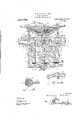
- Figure 1 represents a longitudinal sectional view through the improved valve
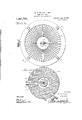
- Fig. 2 represents a top plan view thereof
- Fig; 3 represents a horizontalhsectional view on the line 3+3 of Fig. 1
- v a Fig. 4 represents-a fragmentary sectional viewon the line 4-4 of Fig. 1
- Fig. 5 represents a detail sectional View on the line 5-5 of Fig. ,1.
- v s 7 Referring to the drawingin detail, wherein similar reference numerals designate cor responding parts throughout the several views, the numeral 5 indicates the cylindrical-casing of the valve, having theeXternal flange 6 at the upper open end thereof upon which is supported the top plate 7 The top plate 7 is secured in positionupon theflange' Specification of Letters Iatent.
- a plurality of a e ns 12, is at 14L arranged in posed relation PatentedAug,21, 19 7, i Application filed August 29,1916.
- Serial No.117,442 i lplateii is formed with ajcircu-i i 1 within ,the casing 5 and are formedwith ports 15, 16 and 17, when moved into a registration, free passage of liquid lowermost valve section to permit 14 is arranged in respectively, adapted, F therethrough.
- valve cas ng spaced relation to the bottom; 18 ofthe valve cas ng, providing an inlet chamber 19, com- 3 mun cating with an inlet passage ,20 ar ranged substantially at right angles to the port l? 1n the lowermost valve section 1 1,
- Thelowermost valve section 1 1 is formed with an integral lug 21, which projects axially therefrom and i i s engaged by anadjustable screw 22 fitted in a plug 23 securedin an aperture formed in thebottomvof the casing-5.
- the screw 22 normally retainsthe Valve sections in p0: sition in thecasin'g and the loose move mentof thepvalve fsections incident to the wear of the screw 22 is compensated for by an expansion spring 241, which is confined betweenthe plug 23 andithe lowermost valve section 14; v h I; a a a A relatively stationary, circular plate 25 is fitted in a groove 26 formed in the upper openend of the casing 5 and is locked in position therein Joya-pin 27 .1
- the plate 25 is iormed with a transverse passage 28' adapted tobe alined withthe ports in the several valve sections, so as to permit fluid to pass from the chamber. 19 through the ports 17, 16,15 and 28 tothe .outlet chama beI' v i j m 1 1
- a supporting plate 29 issecured, in position above the top plate 7 by the bolts Sand.
- the upper terminals of the several stems 32 33 and- 34 are of polygonal formation and are'engaged in "correspondingly shaped openings in a plurality of. arms 235,; 36 and 37 which are 's'ecure'd' in position onwthe respective v'alve -stems
- the extreme'upper'end of the relatively longf-valve' -'s tem 34 is externallyscrew threadediand' awvingnut-38 is fitted thereon; whereby theseveral arms 35; seems?- are secured in position-upon the.
- ecti've stem'sw --use,-a person familiar with the combin tion of: th'e valve-may adjust severalarms 35, stand 37 upon the dial so as toregisten-the several ports l5g l6' and117 with the ports 28 in'tlie plate 25,*and thusopen'coin' munication between theinlet and outlet chambers 19 and 26 and permit liquid to have "free passage between these chambers.
- valve including; aca'sing having inlet and 5 outlet portstherein, an adjustable plate having a port therein, 'means sec'ur-' irig said plate in adjnsted position-, a pluralityof valve sections rotatably mounted in said casi-ng having ports therein adapted to be moved into registration with each other and with the ports in said plate,"and means for adjusting said valve sectionsi 215Avalve including a casing' having inlet and-"ioutletports-therein; adjustable 'pl'a secured in said casing-having a port therein; a -plurality of valve sections rotatab'ly mounted in said casing" having port's therein adapted to be moved into registration with each" other and w-iththe-port in said plate the ports in said valve sections and said plate being disposed in angular relation to the inlet and outlet ports in said casing, and means for adjusting said valve sections.
- a valve including acasing, a top plate secured upon'said casing; said casing and top plate having inlet and outlet ports, a plate ad ustablysecured 111 said casing having a port therein, a plurality of valve sections rotatably mounted in said casing having ports the-reinadapted to be moved into registration with the port in said plate to open communication between the inlet and outletports insaidcasingand top plate, stems carried by said valve sections and extending eXteriorly-oi said casing, a dial supportedabove said casing, and arms carried bythe several stems andmovable over said dial to adjust said valve sections.
- a valve including-a casing having in-- lot and outlet ports and a circular outlet passage communicating with the outlet )ort an ad'ustable slate havin a trans l a v a verselyextending port permanently communicatl'ngwith the clrcular outlet passage, and a valve arranged in said casing adapted to be moved into registration with the port in the plate to open coirnnunication between the. inlet and outlet ports of the casing;
- A- valve including a casing having inlet and outlet ports and a circular outlet passage communicating withthe outlet port, a plate adjustably positioned in the casing having a transversely"extending port munication between the inlet and outlet the outlet passage, means for securing said plate in various adjusted positions in said casing, and a plurality of valve sections arranged in said casing having ports therer in adapted to be moved into registration with the ports in said plate to open comnatures in presence of two Witnesses.
Landscapes
- Engineering & Computer Science (AREA)
- Mechanical Engineering (AREA)
- Check Valves (AREA)
Description
M. M. LlFF & W. R. HON.
COMBINATION VALVE.
APPLICATION FILED AuG.29. I916.
Patented Aug. 21, 1917.
2 SHEETS-SHEET l.'
mam STATES mwiow "iiapison M. LIFE la WILLIAM a. non, or 'coiicnr'rrolv JUNCTION, lviissouiiilf I T all whom it may concern: H v
a Be it known that wefMAnIsoN M. LIFF andWILLIAM R. HoN, citizens of the United States, residing at Conception Junction, in
thecounty of Nodaway and State of Missouri, have invented certain new and useful Improvements in Combinationwvalves; and we do hereby declare the following to be a full, clear, andexact description oftheinvention, suchjas will enable other skilled in the 'art to which it appertains to make and use the, same. a
This invention has for its object topro vide an improved valvewhich may-not be opened'by unauthorized persons and is par- I ticularly adapted forusein controlling the flow of liquid fuel to the explosive engine of a motor vehicle, although it isnot necessarily limited to suoh iuse,
Another object is the provision of a valve having the inlet and outlet 1 ports arranged out of line with the ports 1 in the valve sections, so as to prevent an unauthorized pera son disconnectingthe pipes'leading to and 25 fromsthe valve and inserting an instrument inwthe valveports in order to ascertain the combination of the valve.
1 With these and other objects in view,.the
invention consists in the novel construction,
combination and arrangement of parts as will be hereinafter specifically described,
claimed and illustratedin the accompanying drawings, in which: A
Figure 1 represents a longitudinal sectional view through the improved valve,
Fig; 2 represents a top plan view thereof, Fig; 3 represents a horizontalhsectional view on the line 3+3 of Fig. 1, v a Fig. 4 represents-a fragmentary sectional viewon the line 4-4 of Fig. 1, and
' Fig. 5 represents a detail sectional View on the line 5-5 of Fig. ,1. v s 7 Referring to the drawingin detail, wherein similar reference numerals designate cor responding parts throughout the several views, the numeral 5 indicates the cylindrical-casing of the valve, having theeXternal flange 6 at the upper open end thereof upon which is supported the top plate 7 The top plate 7 is secured in positionupon theflange' Specification of Letters Iatent.
with a radial outletport 11.
' COMBINATION-VALVE.
A plurality of a e ns 12,, is at 14L arranged in posed relation PatentedAug,21, 19 7, i Application filed August 29,1916. Serial No.117,442 i lplateiiis formed with ajcircu-i i 1 within ,the casing 5 and are formedwith ports 15, 16 and 17, when moved into a registration, free passage of liquid lowermost valve section to permit 14 is arranged in respectively, adapted, F therethrough. The
spaced relation to the bottom; 18 ofthe valve cas ng, providing an inlet chamber 19, com- 3 mun cating with an inlet passage ,20 ar ranged substantially at right angles to the port l? 1n the lowermost valve section 1 1,
so as to prevent an unauthorized person i from inserting an instrument through the port 20 and the ports in the several valve sect onsito aline the latter. Thelowermost valve section 1 1 is formed with an integral lug 21, which projects axially therefrom and i i s engaged by anadjustable screw 22 fitted in a plug 23 securedin an aperture formed in thebottomvof the casing-5. The screw 22 normally retainsthe Valve sections in p0: sition in thecasin'g and the loose move mentof thepvalve fsections incident to the wear of the screw 22 is compensated for by an expansion spring 241, which is confined betweenthe plug 23 andithe lowermost valve section 14; v h I; a a a A relatively stationary, circular plate 25 is fitted in a groove 26 formed in the upper openend of the casing 5 and is locked in position therein Joya-pin 27 .1 The plate 25 is iormed with a transverse passage 28' adapted tobe alined withthe ports in the several valve sections, so as to permit fluid to pass from the chamber. 19 through the ports 17, 16,15 and 28 tothe .outlet chama beI' v i j m 1 1 A supporting plate 29 issecured, in position above the top plate 7 by the bolts Sand.
through the intermediate valve 13 and the stems, 33-and 32 terminates above the upper terminalbfthe stem 33. The upper terminals of the several stems 32 33 and- 34: are of polygonal formation and are'engaged in "correspondingly shaped openings in a plurality of. arms 235,; 36 and 37 which are 's'ecure'd' in position onwthe respective v'alve -stems The extreme'upper'end of the relatively longf-valve' -'s tem 34 is externallyscrew threadediand' awvingnut-38 is fitted thereon; whereby theseveral arms 35; seems?- are secured in position-upon the. ecti've stem'sw =--use,-a person familiar with the combin tion of: th'e valve-may adjust severalarms 35, stand 37 upon the dial so as toregisten-the several ports l5g l6' and117 with the ports 28 in'tlie plate 25,*and thusopen'coin' munication between theinlet and outlet chambers 19 and 26 and permit liquid to have "free passage between these chambers. Tdcut off communication the arms 35, 36' and 3'7T' areadj-ustedso as to move the ports of theseveralfvalve sections out of -aline-v ment: 5 In order to" change the combination of the valve the pin 27 {is removed from the aperturein the 'plate 25fa'nd 1n the casings,
' and theposition oftheplate ischanged with relation -t(';) the--casing. The; plate as subseqnentl y secured in adjustedposition by inserting apin 27' in an aperture therein and in any onefof'the several recesses 40;-tormed in the asing. The combination of thelock also-be changed by removing the several arms 85,-36and 37iand replacing them in adiflerent 1 position upon the upper terminals of the several stems 32, 38 and 3a.
What I we claim is;-
f "1 rik valve including; aca'sing having inlet and 5 outlet portstherein, an adjustable plate having a port therein, 'means sec'ur-' irig said plate in adjnsted position-, a pluralityof valve sections rotatably mounted in said casi-ng having ports therein adapted to be moved into registration with each other and with the ports in said plate,"and means for adjusting said valve sectionsi 215Avalve including a casing' having inlet and-"ioutletports-therein; adjustable 'pl'a secured in said casing-having a port therein; a -plurality of valve sections rotatab'ly mounted in said casing" having port's therein adapted to be moved into registration with each" other and w-iththe-port in said plate the ports in said valve sections and said plate being disposed in angular relation to the inlet and outlet ports in said casing, and means for adjusting said valve sections.
, 3. A valve including acasing, a top plate secured upon'said casing; said casing and top plate having inlet and outlet ports, a plate ad ustablysecured 111 said casing having a port therein, a plurality of valve sections rotatably mounted in said casing having ports the-reinadapted to be moved into registration with the port in said plate to open communication between the inlet and outletports insaidcasingand top plate, stems carried by said valve sections and extending eXteriorly-oi said casing, a dial supportedabove said casing, and arms carried bythe several stems andmovable over said dial to adjust said valve sections.
' Avalve-including a casing having inlet'and outlet ports-therein and an outlet passage communicating with the outlet port, a plate arranged in'said casing and having a port therein communicating with theoutlet passage, means arranged within the casing' 'fo'r securing the plate in adjusted position; and a plurality of valve;
sections having ports-therein adapted to be moved intoregistration to-open commumca-- troiibetween the-inlet and outlet ports.
5. A valve including-a casing having in-- lot and outlet ports and a circular outlet passage communicating with the outlet )ort an ad'ustable slate havin a trans l a v a verselyextending port permanently communicatl'ngwith the clrcular outlet passage, and a valve arranged in said casing adapted to be moved into registration with the port in the plate to open coirnnunication between the. inlet and outlet ports of the casing;
6. A- valve including a casing having inlet and outlet ports and a circular outlet passage communicating withthe outlet port, a plate adjustably positioned in the casing having a transversely"extending port munication between the inlet and outlet the outlet passage, means for securing said plate in various adjusted positions in said casing, and a plurality of valve sections arranged in said casing having ports therer in adapted to be moved into registration with the ports in said plate to open comnatures in presence of two Witnesses.
MADISON M. LIFF. WILLIAM R. HON.
Witnesses LEROY C. SMITH,
ports of said casing. HENRY J. BERG.
@opies of this patent may be obtained for five cents each, by addressing the Commissioner of Eatemts. Washington, D. G.
In testimony whereof We aifix our sig
Priority Applications (1)
| Application Number | Priority Date | Filing Date | Title |
|---|---|---|---|
| US11744216 US1237795A (en) | 1916-08-29 | 1916-08-29 | Combination-valve. |
Applications Claiming Priority (1)
| Application Number | Priority Date | Filing Date | Title |
|---|---|---|---|
| US11744216 US1237795A (en) | 1916-08-29 | 1916-08-29 | Combination-valve. |
Publications (1)
| Publication Number | Publication Date |
|---|---|
| US1237795A true US1237795A (en) | 1917-08-21 |
Family
ID=3305612
Family Applications (1)
| Application Number | Title | Priority Date | Filing Date |
|---|---|---|---|
| US11744216 Expired - Lifetime US1237795A (en) | 1916-08-29 | 1916-08-29 | Combination-valve. |
Country Status (1)
| Country | Link |
|---|---|
| US (1) | US1237795A (en) |
Cited By (1)
| Publication number | Priority date | Publication date | Assignee | Title |
|---|---|---|---|---|
| US3411525A (en) * | 1964-04-28 | 1968-11-19 | Distillers Co Yeast Ltd | Fluid sampling valves |
-
1916
- 1916-08-29 US US11744216 patent/US1237795A/en not_active Expired - Lifetime
Cited By (1)
| Publication number | Priority date | Publication date | Assignee | Title |
|---|---|---|---|---|
| US3411525A (en) * | 1964-04-28 | 1968-11-19 | Distillers Co Yeast Ltd | Fluid sampling valves |
Similar Documents
| Publication | Publication Date | Title |
|---|---|---|
| US1237795A (en) | Combination-valve. | |
| US759246A (en) | Faucet. | |
| US711121A (en) | Hydraulic balanced valve. | |
| US1240734A (en) | Lock-valve. | |
| US873984A (en) | Compressed-fluid charging and discharging device. | |
| US87538A (en) | Improvement in steam-engine rotary valves | |
| US396858A (en) | Relief-valve | |
| US673165A (en) | Device for controlling flow of water in pipes. | |
| US49624A (en) | Improvement in globe oil-cups | |
| US585383A (en) | Teain pipe valte foe steam cae heating systems | |
| US1226796A (en) | Automatic drain-valve. | |
| US378140A (en) | Throttle-valve | |
| US722058A (en) | Reducing-valve. | |
| US77517A (en) | Albert moore and a | |
| US166393A (en) | Improvement in globe-valves | |
| US586740A (en) | Indicator for valves | |
| US75952A (en) | Improvement in valves foe watee-pipes | |
| US51329A (en) | Improvement in balanced plug-valves | |
| US992069A (en) | Safety attachment for gas-pipes. | |
| US601244A (en) | Magnus p | |
| US690098A (en) | Cut-off valve. | |
| US150344A (en) | Improvement in fluid-meters | |
| US475585A (en) | Reducing-valve | |
| US90696A (en) | Improvement in steam-engine governors | |
| US57418A (en) | Improvement in steam-engine oil-cups |