US1237762A - Wheelwright-machine. - Google Patents
Wheelwright-machine. Download PDFInfo
- Publication number
- US1237762A US1237762A US7258016A US7258016A US1237762A US 1237762 A US1237762 A US 1237762A US 7258016 A US7258016 A US 7258016A US 7258016 A US7258016 A US 7258016A US 1237762 A US1237762 A US 1237762A
- Authority
- US
- United States
- Prior art keywords
- wheel
- bed plate
- shaft
- sprocket
- machine
- Prior art date
- Legal status (The legal status is an assumption and is not a legal conclusion. Google has not performed a legal analysis and makes no representation as to the accuracy of the status listed.)
- Expired - Lifetime
Links
- 241000600039 Chromis punctipinnis Species 0.000 description 2
- 238000010276 construction Methods 0.000 description 2
- 230000000994 depressogenic effect Effects 0.000 description 2
- 210000002832 shoulder Anatomy 0.000 description 2
- 210000003141 lower extremity Anatomy 0.000 description 1
- 210000001364 upper extremity Anatomy 0.000 description 1
Images

Classifications
-
- B—PERFORMING OPERATIONS; TRANSPORTING
- B23—MACHINE TOOLS; METAL-WORKING NOT OTHERWISE PROVIDED FOR
- B23Q—DETAILS, COMPONENTS, OR ACCESSORIES FOR MACHINE TOOLS, e.g. ARRANGEMENTS FOR COPYING OR CONTROLLING; MACHINE TOOLS IN GENERAL CHARACTERISED BY THE CONSTRUCTION OF PARTICULAR DETAILS OR COMPONENTS; COMBINATIONS OR ASSOCIATIONS OF METAL-WORKING MACHINES, NOT DIRECTED TO A PARTICULAR RESULT
- B23Q3/00—Devices holding, supporting, or positioning work or tools, of a kind normally removable from the machine
- B23Q3/155—Arrangements for automatic insertion or removal of tools, e.g. combined with manual handling
- B23Q3/157—Arrangements for automatic insertion or removal of tools, e.g. combined with manual handling of rotary tools
- B23Q3/15706—Arrangements for automatic insertion or removal of tools, e.g. combined with manual handling of rotary tools a single tool being inserted in a spindle directly from a storage device, i.e. without using transfer devices
-
- Y—GENERAL TAGGING OF NEW TECHNOLOGICAL DEVELOPMENTS; GENERAL TAGGING OF CROSS-SECTIONAL TECHNOLOGIES SPANNING OVER SEVERAL SECTIONS OF THE IPC; TECHNICAL SUBJECTS COVERED BY FORMER USPC CROSS-REFERENCE ART COLLECTIONS [XRACs] AND DIGESTS
- Y10—TECHNICAL SUBJECTS COVERED BY FORMER USPC
- Y10T—TECHNICAL SUBJECTS COVERED BY FORMER US CLASSIFICATION
- Y10T29/00—Metal working
- Y10T29/51—Plural diverse manufacturing apparatus including means for metal shaping or assembling
- Y10T29/5104—Type of machine
- Y10T29/5105—Drill press
-
- Y—GENERAL TAGGING OF NEW TECHNOLOGICAL DEVELOPMENTS; GENERAL TAGGING OF CROSS-SECTIONAL TECHNOLOGIES SPANNING OVER SEVERAL SECTIONS OF THE IPC; TECHNICAL SUBJECTS COVERED BY FORMER USPC CROSS-REFERENCE ART COLLECTIONS [XRACs] AND DIGESTS
- Y10—TECHNICAL SUBJECTS COVERED BY FORMER USPC
- Y10T—TECHNICAL SUBJECTS COVERED BY FORMER US CLASSIFICATION
- Y10T408/00—Cutting by use of rotating axially moving tool
- Y10T408/55—Cutting by use of rotating axially moving tool with work-engaging structure other than Tool or tool-support
- Y10T408/557—Frictionally engaging sides of opening in work
Definitions
- This invention relates to machines for the use of'wheelwrights, blacksmiths and others, the object in view being toproduce a machine which will facilitate the various operations upon vehicle wheels including the original construction of the wheel, the repairing of the same, the application of new spokes and tires to the felly and the boring of holes and placing of bolts and nuts to secure the parts together.
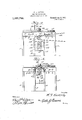
- Fig. 2 1s a vertical longitudinal section through the same showing a wheel partly in elevation and partly lliSGCtlOIl.
- FIG. 3 is an end elevation of the same showing the rack bars.
- Fig. sis avertical cross section on the line H of Fig. 1.
- the main frame of the wheel stand is rectangular in plan comprising the parallel. side bars 1, the end bars 2 connecting the same and the intermediate cross bars 3, all of said parts being fastenedtogether in rigid relation to each other.
- y I p x Extending outwardly from the side bars 1' at about'the center thereof are wings 4, the latter being hinged at 5 to the side bars 1 in order that they may be folded inwardly against the side bars 1 for the sake of compactness and to enable the machine as a whole to be stored in a small space.
- Hooks 6 are employed to hold the wings 4: at right angles to the side bars 1, said hooksbeing shown as pivotally connected at 7 to the side bars 1 and movable into and out of engagement with eyes 8 on the wings 4.
- the main frame is supported at a suitable elevation by means of legs 9 connected by cross braces 10 and the wings 4 are also supported by additionallegs 11.
- a horizontal guide bar 12 extends across the elevated frame and connects the side bars 1 thereof, said guide bar being formed with a guide opening 13in which is slidably mounted a vertical wheel supporting'shaft 14 upon which the vehicle wheel is adapted to be rotatably mounted, said wheel being indicated at 15.
- the lower extremity of the shaft or spindle is supported by a hand operated lever 16to which the shaft 14L is shown as pivotally connected at
- the lever 16 is hinged atone end as shown at 18 to the supporting legs at one end of the frame a'ndthe opposite end of said lever extends beyond the opposite end of the frame and bet'weena pair of vertical rack bars 19: andQO onelof which is provided with shoul-- ders or teeth 21 for supporting the end of the lever.
- the other rack bar being 'pr'ovided with shoulders or teeth 22 for holding-the end of the lever depressed.
- the collar 23 on the shaft or spindle 1 1 forms a support on which the hub of the wheel 15 rests.
- a nut 24 is threaded'on the upper extremity of the shaft or spindle 14 so as to clamp the wheel 15 on said shaft and enable said wheelto be raised andlowered until the rim and felly thereof are brought into the desired relation to the drill and socket wrench hereinafter described.
- the 26 designates a bed plate whichisslidable longitudinally of thehorizontal main frame of the stand, said bed plate cooperating with guides 27.
- the bed plate is providedwithan upstanding head stock 28 and a tail stock 29.
- a live spindle 30 is journaled in the headstock 28 and another live spindle 31 is journaled in thetail stock 29.
- the spindle 30 is provided with a chuck 32 adapted to receive a drill 33 while the live spindle 31 is provided with achuck 34 adapted to'receive a socket wrench 35.
- the spindles 30 and 31 are in alinement with each other and when the vehicle wheel 15 is in place the felly and tire of the wheel lie between the said live spindles.
- Each of the spindles 30 and 31 has fast thereon a sprocket wheel 36 from which a sprocket chain 37 extends downwardly around another sprocket wheel 38 on a rotary driving shaft 39 located below the bed plate 26 and journaled in bearings on the frame, said driving shaft 39 being immovable longitudinally.
- the sprocket wheels 38 have a sliding and feathered engagement with the shaft 39 and are shifted longitudinally of said shaft in accordance with the movement of the sliding bed plate 26, the sprocket wheels 38 being connected with the bed plate 26 by means of arms 40 carried by the bed plate and extendvided with a folding hand crank 45pivot ally connected thereto at 46, the hand crank beingused whenever found necessary and being merely an adjunct to the power transmitting belt LL- I I
- the live spindle 30 passes througha journal boX 47 which is pivotally mounted on a verticalaXis as shown at 48 in a movable hearing or support 49 which is slidable transversely of the bed plate 26. Means are provided for adjusting the bearing 49, the
- Fig,- 4 comprising a pair of eccentric or cam levers 50 having connected thereto clamping bolts 51 which extend downwardly through slots 52 in'the bed plate 26 and having on their lower ends heads 53 which engage the under side of said bed plate.
- the cam levers 50 By loosening the cam levers 50, the bearingor support 49,1naybe shifted laterally to one side or the other of the center, thereby correspondingly chang ing the angle of the live spindle 30.
- a hole may be drilled directly through the tire and felly on a true diametrical line of the vehicle wheel or the hole maybe drilled at an angle to one side or the other of the'diametrical line of the. wheel.
- the lever 16 Whenit is necessary tov revolve the wheel, as is the case when boring holes in the tire and felly to. receive the bolts, the lever 16 may be elevated or depressed and brought into engagement withthe desired tooth of the" supporting rack bar.19.. In case it is desired to clamp the wheel against rotation,
- a wheel. stand embodying a horizontal frame, a vertically'adjustable wheel supporting shaft, a horizontally slidable bed plate, guiding means for said plate on said frame, a stock and live spindle carried by said bed plate, a driving shaft, sprocket wheels in said live spindle and driving shaft, the sprocket wheel on the driving shaft being feathered and slidable thereon, a sprocket chain passing around said sprocket wheels, and an arm onthe bed plate engaging the sprocket wheel on the driving shaft to shift the last named sprocket wheel.according to the movement of the bed plate.
- a wheel stand embodying a horizontal frame, a vertically adjustable wheel supporting shaft, a horizontally slidable bed plate, guiding means for said plate on said frame, a stock and live spindle carried by said bed plate, a driving shaft, sprocket .wheels in said live spindle and driving shaft,
- the sprocket wheel on'the, driving shaft being feathered and slidable thereon, a sprocket chain passing, around said sprocket wheels, an arm on the bed plate engaging the sprocket wheel on the driving shaft to shift the last named sprocket wheel according to the movement of the bed plate, a live spindle bearing adjustable transversely of the bed plate, a spindle journal box pivotally supported by said bearing, and means for adjusting and fasteningsaid hearing.
Landscapes
- Engineering & Computer Science (AREA)
- Mechanical Engineering (AREA)
- Testing Of Balance (AREA)
Description
W. S. EASTERLY.
WHEELWRIGHT MACHINE.
APPLICATION FILED JAN. I7, 1916. 'LQEWWQI 4 Patented.A11g.2I,1917.
2 SHEETS-SHEET I.
Elmw/m Witwwaea I myam w. s. EASTERLY. WHEELWRIGHT MACHINE.
'APPLlCATION FILED MN. H, 191-6.
3% u. Patented Allg- 2 SHEETS-SHEET 2- l if wi-rirnLwmenr-iiacriiivn- I Specification of underwent.- Patentediiugl 21', 19 1 '7.
Application filed January 17, 1916. Serial No. 7%,580."
To all whom it may concern:
"Be it known that I, VVILBERT S. EASTERLY, a citizen of theUnited States, residing at WValdron, in the county of Harper and State of Kansas, have invented new and useful Improvements in Wheelwright Machines, of which the following is a specification.
This invention relates to machines for the use of'wheelwrights, blacksmiths and others, the object in view being toproduce a machine which will facilitate the various operations upon vehicle wheels including the original construction of the wheel, the repairing of the same, the application of new spokes and tires to the felly and the boring of holes and placing of bolts and nuts to secure the parts together.
With the above and other objects in view, the invention consists inf the novel construction, combination and arrangement of parts, as herein described; illustrated and claimed.
In the accompanying drawings Figurel is a plan View of a machine embodying the present invention.
Fig. 2 1s a vertical longitudinal section through the same showing a wheel partly in elevation and partly lliSGCtlOIl.
.Fig. 3 is an end elevation of the same showing the rack bars. t
Fig. sis avertical cross section on the line H of Fig. 1.
The main frame of the wheel stand is rectangular in plan comprising the parallel. side bars 1, the end bars 2 connecting the same and the intermediate cross bars 3, all of said parts being fastenedtogether in rigid relation to each other. y I p x Extending outwardly from the side bars 1' at about'the center thereof are wings 4, the latter being hinged at 5 to the side bars 1 in order that they may be folded inwardly against the side bars 1 for the sake of compactness and to enable the machine as a whole to be stored in a small space. Hooks 6 are employed to hold the wings 4: at right angles to the side bars 1, said hooksbeing shown as pivotally connected at 7 to the side bars 1 and movable into and out of engagement with eyes 8 on the wings 4.
The main frame is supported at a suitable elevation by means of legs 9 connected by cross braces 10 and the wings 4 are also supported by additionallegs 11., A horizontal guide bar 12 extends across the elevated frame and connects the side bars 1 thereof, said guide bar being formed with a guide opening 13in which is slidably mounted a vertical wheel supporting'shaft 14 upon which the vehicle wheel is adapted to be rotatably mounted, said wheel being indicated at 15. The lower extremity of the shaft or spindle is supported by a hand operated lever 16to which the shaft 14L is shown as pivotally connected at The lever 16 is hinged atone end as shown at 18 to the supporting legs at one end of the frame a'ndthe opposite end of said lever extends beyond the opposite end of the frame and bet'weena pair of vertical rack bars 19: andQO onelof which is provided with shoul-- ders or teeth 21 for supporting the end of the lever. the other rack bar being 'pr'ovided with shoulders or teeth 22 for holding-the end of the lever depressed. The collar 23 on the shaft or spindle 1 1 forms a support on which the hub of the wheel 15 rests. A nut 24 is threaded'on the upper extremity of the shaft or spindle 14 so as to clamp the wheel 15 on said shaft and enable said wheelto be raised andlowered until the rim and felly thereof are brought into the desired relation to the drill and socket wrench hereinafter described.
26 designates a bed plate whichisslidable longitudinally of thehorizontal main frame of the stand, said bed plate cooperating with guides 27. The bed plate is providedwithan upstanding head stock 28 and a tail stock 29. A live spindle 30 is journaled in the headstock 28 and another live spindle 31 is journaled in thetail stock 29. i The spindle 30 is provided with a chuck 32 adapted to receive a drill 33 while the live spindle 31 is provided with achuck 34 adapted to'receive a socket wrench 35. The spindles 30 and 31 are in alinement with each other and when the vehicle wheel 15 is in place the felly and tire of the wheel lie between the said live spindles. Each of the spindles 30 and 31 has fast thereon a sprocket wheel 36 from which a sprocket chain 37 extends downwardly around another sprocket wheel 38 on a rotary driving shaft 39 located below the bed plate 26 and journaled in bearings on the frame, said driving shaft 39 being immovable longitudinally. The sprocket wheels 38 have a sliding and feathered engagement with the shaft 39 and are shifted longitudinally of said shaft in accordance with the movement of the sliding bed plate 26, the sprocket wheels 38 being connected with the bed plate 26 by means of arms 40 carried by the bed plate and extendvided with a folding hand crank 45pivot ally connected thereto at 46, the hand crank beingused whenever found necessary and being merely an adjunct to the power transmitting belt LL- I I The live spindle 30 passes througha journal boX 47 which is pivotally mounted on a verticalaXis as shown at 48 in a movable hearing or support 49 which is slidable transversely of the bed plate 26. Means are provided for adjusting the bearing 49, the
same being best illustrated in Fig,- 4 and comprisinga pair of eccentric or cam levers 50 having connected thereto clamping bolts 51 which extend downwardly through slots 52 in'the bed plate 26 and having on their lower ends heads 53 which engage the under side of said bed plate. By loosening the cam levers 50, the bearingor support 49,1naybe shifted laterally to one side or the other of the center, thereby correspondingly chang ing the angle of the live spindle 30. In this way a hole may be drilled directly through the tire and felly on a true diametrical line of the vehicle wheel or the hole maybe drilled at an angle to one side or the other of the'diametrical line of the. wheel.
Whenit is necessary tov revolve the wheel, as is the case when boring holes in the tire and felly to. receive the bolts, the lever 16 may be elevated or depressed and brought into engagement withthe desired tooth of the" supporting rack bar.19.. In case it is desired to clamp the wheel against rotation,
blocks may be placed upon the main frame of the stand and the vehicle wheel drawn downward tightly thereon and so held by moving the lever.16 into engagement with Copies of thispatent may be obtained for the proper tooth of the rack bar 20. The machine as a whole is adapted to vehicle wheels of different sizes and will be found of great utility to wheelwrights, blacksmiths and-mechanics in general.
Having thus described my invention, I claim 1. A wheel. stand embodying a horizontal frame, a vertically'adjustable wheel supporting shaft, a horizontally slidable bed plate, guiding means for said plate on said frame, a stock and live spindle carried by said bed plate, a driving shaft, sprocket wheels in said live spindle and driving shaft, the sprocket wheel on the driving shaft being feathered and slidable thereon, a sprocket chain passing around said sprocket wheels, and an arm onthe bed plate engaging the sprocket wheel on the driving shaft to shift the last named sprocket wheel.according to the movement of the bed plate.
2. A wheel stand embodying a horizontal frame, a vertically adjustable wheel supporting shaft, a horizontally slidable bed plate, guiding means for said plate on said frame, a stock and live spindle carried by said bed plate, a driving shaft, sprocket .wheels in said live spindle and driving shaft,
the sprocket wheel on'the, driving shaft being feathered and slidable thereon, a sprocket chain passing, around said sprocket wheels, an arm on the bed plate engaging the sprocket wheel on the driving shaft to shift the last named sprocket wheel according to the movement of the bed plate, a live spindle bearing adjustable transversely of the bed plate, a spindle journal box pivotally supported by said bearing, and means for adjusting and fasteningsaid hearing.
In testimony whereof I aiiiX my signature in presence of two witnesses.
, WILBERT S. EASTERLY. Witnesses:
vJOHN WV. VARREL,
Nona E. JonNsoN.
five cents each, by addressing the Commissioner of-Patents, Washington, Q.
Priority Applications (1)
| Application Number | Priority Date | Filing Date | Title |
|---|---|---|---|
| US7258016A US1237762A (en) | 1916-01-17 | 1916-01-17 | Wheelwright-machine. |
Applications Claiming Priority (1)
| Application Number | Priority Date | Filing Date | Title |
|---|---|---|---|
| US7258016A US1237762A (en) | 1916-01-17 | 1916-01-17 | Wheelwright-machine. |
Publications (1)
| Publication Number | Publication Date |
|---|---|
| US1237762A true US1237762A (en) | 1917-08-21 |
Family
ID=3305579
Family Applications (1)
| Application Number | Title | Priority Date | Filing Date |
|---|---|---|---|
| US7258016A Expired - Lifetime US1237762A (en) | 1916-01-17 | 1916-01-17 | Wheelwright-machine. |
Country Status (1)
| Country | Link |
|---|---|
| US (1) | US1237762A (en) |
-
1916
- 1916-01-17 US US7258016A patent/US1237762A/en not_active Expired - Lifetime
Similar Documents
| Publication | Publication Date | Title |
|---|---|---|
| US1237762A (en) | Wheelwright-machine. | |
| US548298A (en) | Island | |
| US896579A (en) | Wheelwright's machine. | |
| US575538A (en) | Drill and tap machine | |
| US1003340A (en) | Harrow-disk sharpener. | |
| US726662A (en) | Boring and reaming machine. | |
| US610036A (en) | ensign | |
| US611540A (en) | Tire-bolting machine | |
| US519752A (en) | yarnell | |
| US1138130A (en) | Tire-bolting machine. | |
| US576305A (en) | Chijsetts | |
| US493738A (en) | Pulley-lathe | |
| US290303A (en) | Machine for gilding cards | |
| US697056A (en) | Rubber-tire-setting machine. | |
| US1063497A (en) | Barrel-head-shaping machine. | |
| US332699A (en) | Meets | |
| US1152215A (en) | Bolt-tightener. | |
| US334647A (en) | Car-wheel-truing machine | |
| US1117920A (en) | Head-stock. | |
| US1175969A (en) | Turning and fluting machine. | |
| US920493A (en) | Work-holder for drill-presses. | |
| US960002A (en) | Portable boring-machine. | |
| US1039503A (en) | Wheel boring and facing machine. | |
| US418520A (en) | kauffman | |
| US427021A (en) | John m |