US1237703A - Calculating-machine. - Google Patents
Calculating-machine. Download PDFInfo
- Publication number
- US1237703A US1237703A US71027312A US1912710273A US1237703A US 1237703 A US1237703 A US 1237703A US 71027312 A US71027312 A US 71027312A US 1912710273 A US1912710273 A US 1912710273A US 1237703 A US1237703 A US 1237703A
- Authority
- US
- United States
- Prior art keywords
- multiplier
- indicators
- digits
- denomination
- gear
- Prior art date
- Legal status (The legal status is an assumption and is not a legal conclusion. Google has not performed a legal analysis and makes no representation as to the accuracy of the status listed.)
- Expired - Lifetime
Links
Images


Classifications
-
- G—PHYSICS
- G06—COMPUTING OR CALCULATING; COUNTING
- G06C—DIGITAL COMPUTERS IN WHICH ALL THE COMPUTATION IS EFFECTED MECHANICALLY
- G06C15/00—Computing mechanisms; Actuating devices therefor
- G06C15/08—Multiplying or dividing devices; Devices for computing the exponent or root
Definitions
- Calculating machines for performing the ordinary arithmetical computations may be grouped into those primarily adapted to perform addition and subtraction, herein termed adding machines, and those primarily adapted to perform multiplication and division, herein termed multiplying machines"
- adding machines those primarily adapted to perform addition and subtraction
- multiplying machines The essential diflerences in construction of machines of these two groups results from the operations involved in addition as distinguished from the operations involved in multiplication.
- Addition may be considered as the operation of finding the sum of the products of each number to be added and the digit 1 of the units denomination
- multiplication consists in finding the product of the multiplicand factor and the multiplier factor wherein the multiplier digits have different denominations and any value from 0 to 9.
- the separate products to be added are not indented in denomination relatively to each other since the multiplier digit is always of units denomination, and furthermore the separate di 'ts 0f the numbers to be added are registere on the adding mechanism without modification since the multiplier digit always has a value of 1.
- the partial results obtained by multi lying the multiplicand factor by each mu tiplier di it must be registered on difierent series 0 the indicators of the adding mechanisms in accordance with the different denominations of the multiplier, and furthermore each multiplicand digit must be multiplied by digits of values ranging from O to 9.
- the multiplying mechanism may comprise driving mechanisms including variable-ratio ,gearings which'are set in accordance with the individual digits of one factor and which are actuated in accordance with the digits of the other factor to register the partial results on the product indicators; or they may comprise driving mechanisms hav ing members on which are represented the separate digits of partial products and which are positioned in accordance with the digits to be multiplied together to register the partial products on the adding mechanism. In all cases the partial results are registered in proper denominational relation on the adding mechanism to indicate thereon the product of the multiplicand and multiplier.
- the present invention relates to calculating machines of the kind herein termed multiplying machines, and more specifically to one primarily adapted to mechanically attain an indication of the product of factors having any number of dlgits up to the number provided for, wherein the factors may have di its of any value and in any sequence.
- T e machine also readily performs division, addition and subtraction, and may easily be provided with printing mechamsm and other devices suitable for auditing and analogous work.
- An object of the invention is to provide a non-indenting adding mechanism on which the partial results are added or subtracted without shifting the indicators in denomination, together with a multiplying mechanism which is likewise non-shiftable in denomination, in combination with suitable devices for connecting the multiplying mechanism with difierent series of the indicators of the adding mechanism in accordance with the different denominations of the n'iultiplier.
- any suita 1e form of at ding mechanism may be used, and the transfer of the units to higher denominations may be delayed or may be made simultaneously with the adding movements.
- any suitable form of multiplying mechanism may be used, and the driving mechanisms thereof may comprise variable-ratio gearings, members on which partial products are represented, or otherwise, and they may be operated by hand or by any suitable form of motor.
- the connections between the multiplying and adding mechanisms may be constructed in many ways, the-essential condition being that means be provided for connecting the two mechanisms in various denominational relations without shifting either one relatively to the other...
- each mechanism comprises difi'erential gearings arranged like those in our copending-application Serial No. 680246, filed February 27, 1912-, but provided with a rectifier of novel form and actuated in a novel way for completing the transfer of units between the indicators after each partial result is registered thereon.
- the multiplying mechanism comprises variable-ratio gearings of novel "form and equal in number to the number of 'Inulti-plicand digits provided for.
- Each variable-ratio gearing com prises a disk of novel "form and a gear driven thereby in amounts determined by the position to which the gear is set relatively to the disk. and b'y the amount ofrotation of disk.
- each gear is controlled by a bank of keys, 0 to 9, so that any multiplicand digit may be set up by each variable-ratio gearing, and any multiplicand factor Within the capacity of the machine may be set up by the series of variableratio gearings.
- the disks are collectively turned by a spring motor, and the amount of movement'is controlled by multiplier keys and associated stopping mechanism of novel construction.
- the arrangement of the transmitting connections embodies a novel idea in multiplying machines, and comprises a shaft extending from each indicator of the adding mechanism, except from the one of highest denomination, and anactuating shaft from each gear of the variablematio gearings.
- the actuating shafts areoperatively connected with a d-i.fferent series of indicator shafts for each denomination of the multi lier by depressing any key in the bank 0? that denomination.
- any multiplier key first operatively connects the series of actuating shafts with a series of indicator shaftsin accordance with the denomination of the key and then the spring motor is released to actuate the disks in accordance with the value of the key, so that the products of the separate digits of the multiplicand and multiplier are registered in proper denominational relation on the adding mechanism to indicate thereonthe product of the multiplicand and multiplier.
- Figure 1 represents a top plan of the machine
- Fig. 2 represents an elevation of a part of the clearing mechanism
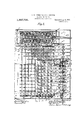
- Fig. 3 represents a plan, partly in section, with the cover removed;
- Fig. 4 represents a plan, partly in section, showing some of the operating parts
- Fig. 5 is an elevation on section line 55 of. Fig. 3;
- Fig. 6 is an elevation on section line 66 of Fig. 3;
- Fig. 7 is an elevation on section line 7-7 of Fig. 3.;
- Fig. 8 represents an enlarged section of the clutches for the multiplier indicators
- Fig. 9 is an enlarged elevation on section line 9-9 of Fig. 3;
- Fig. 10 is a plan on sectionline 10-10 of Fig. 9;
- Fig. 11 is an enlarged elevation on section line 11-11 of Fig. 10;
- Fig. 12 is an enlarged elevation on section line 12-1201? Fig. 3;
- Fig. 13 isan enlarged elevation on section line 1313 of Fig. 3;
- Fig. 14 represents an enlarged plan, partly in section, of a part of the adding audaccumulating mechanisms
- Fig. 15 is an elevation on section line 15-15 of Fig. 3;
- Fig. 16 is an elevation on section line 1610 of Fig. 14;
- Fig. 17 is an enlarged front elevation on section line 17-47 of Fig. 3;
- Fig. 18 is an enlarged elevation on section line 1818 of Fig. 3.
- a machine may be constructed in accordance with the invention for any number of digits in any of the numbers, and. any machine so constructed is also capable of per forming all the mathematical operations on numbers having any lesser number of digits.
- the machine herein shown has a capacity in multiplication of five digits in each of the factors.
- the machine is provided with a casing A having suitable openings for the exteriorly extending parts, and suitable Win- (lOWS for the indicators. 1
- the adding mechanism comprises; the. result indicators and the transfer mechanism for carrying units to next higher denominations, While the accumulating mechanism is similar to the adding mechanism and ac cumulates or totalizes the separate results.
- the construction is similar in many respects to one of the forms described in our co-pending application Serial No. 680246 referred to above, and therefore, it will sufi ice to briefly describe the construction in this application.
- Each difi'erential gearing comprises a driving component, the bevel gear B, fastened on the indicator shaft B; a transfer receiving component, the bevel gear Bf, loosely mounted on shaft 13; and a transfer actuating component, the bevel gear B in mesh with gears B and B and loosely mounted on a stud B of a carrier B which is loosely mounted for rotation on the shaft .B. and fastened to the dial l3 .bya pin B. (See Figs. 3, 9, l4, l5 and 16).
- the digits 0 to 9 are arranged consecutively in the same direction around each of the dials and the windows B and B are provided in the top of the casing A (Fig. 1).
- a cut- .cut-o-ut gear B engages with the ten-tooth .out disk B? secured to a two-tooth segment B.
- the periphery of the cut-out disk runs in the cut-out part of a six-tooth intermediate transfergear B while the segment 13 engages with the six teeth thereof to turn the gear two teeth or. one-third of a rotation when the corresponding dial is passingfrom 9 to Oin addition, or from 0 to 9 in subtraction.
- the six-tooth-part ofthis .75 transfer gear B which is fastened to the transfer receiving component B of the differential gearing.
- the cut-out disk B and the segment B are omitted fromthe highest denomination, while the ten-tooth transfer gear B is omitted from the lowest denomination of both the adding and the accumulating mechanisms.
- the adjacent. differential gearings arereversely arranged so as to bring the ten-tooth transfer gear 13 of one denomination in .line with the toothed segment .B of next lower denomination.
- The-arrangement of the addingi and accumulating" mechanism is such t at upon turningany indicator shaft B the correspondingdriving components B of the add- ;ing and accumulating mechanisms are turned through the same amount.
- the transfer receiving components B of those diiferentialgearings are locked in position as a result of the engagement of the intermediate transfergears B with the respective transfer ears B and 'with the cut-out disks B ⁇ , while the transfer receiving components B oflowest denomination are fastenedto a fixed part of the machine as shown at the right of Fi 14.
- the bevel gears B of the di erential gearings are rolled on their respective transfer receiving components B and turn the dials B through one-half of the amount of rotation ofthe indicator shaft.
- the toothed-segment B advances theten-tooth transfer gear B of the next higher denomination two teeth in theisame direction as the dial, through the intermediate transfer gear B, the transfer receiving component B of that next higher denomination being turned through one fifth of .,a rotation.
- the component B is turned thereby through one-tenth of a rotation in the same direction as by its driving component B, and through the amount produced byone-fifth of a rotation of the shaft 1 B or one'digit. Units are transferred in this way to a higher denomination when the shaft B of that denomination is not being actuated.
- the five shafts B of highest denomination shown at the left'in Fig. 17,- are provided with disks B having five pins,'between which the toes B" of the spring pressed locks 'B" areadapted to fit so as to normally prevent'the respective shafts from turning.
- the locks are so shaped that when any one is pressed from between the pins it also carries all others of lower denomination out of-engagement. In this'way, all shafts up to and including the one of highest denomination engaged by the multi' lying mechanism at any time become-unloc ed, while those of still higher denominations remain locked.
- the means for depressing the toes B out of locking engagement with the disks 13 during the operation of the machine and when clearing indicators will be described hereinafter.
- Each of the dials is polygonal shaped in outline and each of the cam surfaces is round and adapted to engage with the bottom face of its dial to turn the dial ih one direction or the other from a slightly offset position which it may have after the operation of the machine in either direction to a position in which the top and bottom faces are horizontal.
- Each cam D or D comprises a segment of a disk fastened on its shaft I) or 1), respectively.
- the cam D operating on the adding mechanism dial B of lowest denomination i. e.
- each mechanism is rectified from the lowest to the highest denomination in turn, so that the lost motion and back lash between adjacent dials is successively taken up, and all carry movements of the transfer devices, which may have not been finished, are then completed throughout the entire adding mechanism, and all the dials brought to an accurate reading position after the rectifier has done its work. Furthermore. each dial is held in position against movement by the remaining portion of the cam surface just after the dial is rectified, and finally all the dials are simultaneously released by the cams, when the shafts D and D complete their rotation and come to the position shown in 'Fig. 16, whereby the dials B and B may again be actuated by the driving mechanism without interference from the rectifiers.
- the devices provide for rotatin the shafts D and D one rotation after ea h partial result has been registered on the adding and accumulating mechanisms will be described hereinafter.
- the multiplying mechanism comprises the driving mechanism for registering the partial results on the indicators of the adding and accumulating mechanisms.
- Five driving mechanisms are shown, each comprising a variableratio gearing consisting of a disk having actuating means in the form of holes E arranged in circles on the face of the disk and ten radially disposed slots E together with a five-tooth gear E adapted to be moved radially of the disk along any one of the slots so as to be positioned in alinement with any selected circle of holes in accordance with a multiplicand digit.
- the innermost circle comprises ten slots 'so'that when the gear E" is set to this position correspond ing to the digit 1, it is turned throughone j tooth when the disk E is turned through one sector or one-tenth of a rotation.
- the gear will be turned through" a number of teeth equal to the pr'odu'ct'of the having five or less digits, the products of the separate multiplicand digits and *the mill tiplierdigit corresponding to the number of sectors through which the -disks "are] turned, may be registered on the adding and accumulating mechanisms by connecting the gears E with the indicator shafts B without any speed change between them, since each one-fifth rotationof an indicator shaft B advances the respective indicator B one digit, as noted above.
- the gears E engage the locks G as they are being disengaged from the disks E, and vice 'versa.
- variable-ratio gearing of this kind, that is one in'which the ratio of the driving'to the driven speed may be varied in the ratio of the elementary digits 0 to 9, possesses characteristic"advantages in application to calculating machines.
- the disks E may be machined, cast, stamped, or built up in any suitable way with any desired number of sectors having holes, depressions, teeth or other forms of actuating mean s,and the gear may be constructed in a variety of suitable ways and may have other number of teeth or engaging means if desired, the essential condition being that the proper relation be provided between the movement of the variable-ratio gearing and the resulting actuation of the indicators.
- a keyboard comprising five/columns or banks G of multiplicand keys '0 to 9' are provided for positionin 'i-the five gears E relatively to the *disks'i? to set up any multiplicand digits at Willi
- the bank of keys G at the extrem',left in Fig. I is of the highest denomination and positions the upperniost gear E in 'Fig. 3, while the banks tow'ard the"ri'ght are'of successively lower denominations and position the 'gears E toward the bottom respectively.
- each mnltipli and bank has a tapered 'end' but no cut out portion and f simply movesthe locking plate of that bank forwardfto release any key. but without becoming locked itself, and is for thepurpose of changing to'O any multiplicand digit previously setup in its bank.
- Each spring G has sufiicient force to raise the respective key to the position determined by the stop G and the top casing Awhen the key is released from engagement with the locking plate G", and. at the same time to move the corresponding gear E to its 0 position.
- multiplicand indicators "i are fastened on the individual shafts G and show the'multiplicand factor set up thrpu thewindpws G in thetop of easing A. he end of, the shaftfi which carries thegear E is 'ournaled in a bearing block Gr and this look moves alon a slot in the rail G" to support that end oi the shaft whatever position the car may have;
- the journaled pedestals 3r are provided for sup orting the shafts Gtwhere desired. (See igs. 5 and 18).
- b iine stopping atchets E" are nionnted on the shaft f an are associated with control devices to e eqt oneg tent to nine-tenths of a complete rotation of the shafts 1 3 mm E 7, and 9,)
- Each ratchet is provided with ten"te'etli and with a, pirr abulgrnengE'.
- 'he disks 8' have projections 9 o di'fl'erent angiilar eirt'en't which arsarmngedyo strike against the abiitments ,E, o the respective rat'ch'ets- E.
- the ratchet wlll Since the spring.,E is Wound up during; this movement of the disk, the ratchet wlll, when released, be bronght by the spring to its normal position shown in Fig. 9, wherein the front of fl1e a'but ment lies against the projection.
- the ratchet E and disk E for nine-tenths of a rotation are shown in their nor l position, the projection E and the pi occn-' pyin 'the reni aining one-tenth 0 the circum erenee.
- the other ratchets and disk are like this one except that the pro'ections E have the angular extent determined, by the amount of rotation to be permitted in each case.
- the shaft E with the di s E and the shaft E with the stop inge'yice are turned by a spring motorw ich willbe described hereinafter.
- the mechanism associated with the stopping devices to control the rotationof the disks E comprise a multiplier keyboard having five banks H of keys, 1; to 9, and-nine shiftable bars 1 operated thereb and snitably supported, together with e deyices tor releasing the spring motor. see'Figg.
- the bankH of highest denomination is arranged at the left of the multiplier keyboard while the remaining banks decrease in denomination toward the right in' Fig. 1,
- Each bank is provided with a longitudinally shi'ftable bar H for connecting the yariable-ratio gearings with a series of indicators in accordance with the denomination of the multiplier digit, as will be described hereinafter, and each of these bars is arranged to be operated upon dep essionlof any multiplier key in the bank a tapered bottom adaptedto move tothe right in Fig. 6, duri ngthe later part of the depression stroke,- that bar H which corresponds tot-he digit represented by the key.
- the sliifitable bar H corresponding to the denomination of the multiplier digit but irrespecti-veof its value is first moved and then the shiftable bar H correspondingto the value of the multiplier digit but irrespective of its denomination is then moved.
- he springs H? restore the individual keys to their normally raised position determined by; a shoulder on the part H of the key shank and the cover of the casin ,A.
- the mechanism for'the purpose comprises a plurality of balls H arranged; in a traverse race H between the screws H, the balls having the proper size relative to spacing oi: the shiftable bars H and being so arranged that the end H? of any one bar H may enter between the balls through an opening in: the race, but no more than one at a time.
- the variable-ratio gearings cannot be connected to more thanoneseries of indicators at a time, and a multiplier key of one bank cannotbe depressed before a depressed key of another bank is restored.
- the springs H return the bars 2 to their normal position when the multiplier keys are released.
- the bars H have slots H through which extend stationary guide pins H", and are provided with springs H for returning the bars to normal position after actuation.
- the tapered bottom ofthe part H of each multiplier key and the engagingfingers H are so arranged that the bar H reaches its extreme rig t hand position in Fig. 6 inen agement with the corresponding ratchet f near the end of the depression stroke of thekey.
- Each of the bars H is also provided with a dependingpin H engaging a slot in a pivoted frame H rovided with a spring H tending to keep it in the normal position shown in Fig. 9.
- This frame carries a lever H" (see Fig.
- a spring motor is provided for rotating the shafts E, E upon depression of the multiplier keys. (See Figs. 3, 4, 6 and 7). It comprises a spiral spring J, with its inner end fastened to the shaft J and its outer end fastened to the frame of the'machine.
- the gear J carries the springpressed pawl J and is loose on the shaft J but meshed with the gear J
- This gear J is fastened on the shaft J 5 and the bevel gear J is likewise fastencd on this shaft in engagement with-the bevel gear J 7 on the shaft E.
- the mechanism for winding the spring motor comprises a handle J B tight on the shaft J and a toothed segment J loose on the shaft and carrying a pin abutment J adapted to be engaged by the handle.
- the teeth of the segment are in mesh with a gear J to which is fastened a ratchet J tight on the shaft J
- the handle When the handle is pulled in the direction of the arrow in Fig. 4, it strikes against'the abutment J, and then rotates the ratchetJ to wind the spring J from the position to which it previously unwound to a fully wound position, the gear J being locked from theshaftE.
- the spring J returns the handle when'it is released by the operator.
- the spring motor J has sufficient strength and the gearing in terposed between the'spring and the shafts E is suitable for rotating theshafts E and F. through the number of revolutions re+ quired for the various calculations.
- the disks E are rotated in the direction of the arrow in Fig. 18 and'the stopping devices on the shaft E are rotated in the same direction, but for subtraction and division the direction of rotation of the disks E is reversed while that of the shaft E remains as before.
- the handle K is in the position shown in Fig. 1, indicating addition and multiplication, the ten-tooth clutch members K are engaged while the gear K slidably mounted in a key way on the shaft E is out of mesh with the gear K which is loose on the stud K". (See Figs. 3 and 18).
- the clutch members K are disengaged by means of the pivoted arm K which carries a finger engaging the collar of that clutch member which slides in a key way on the shaft E, while the gears K and K become engaged'at the same time.
- the gears, K, 'K and K are permanently in engagement, and since K is fastened to K while K is fast on the shaft E, the direction of rotation of the disks E is then opposite to that of the shaft- E on which the controlling disks are mounted.
- the arrangement is such that the gears K and-K' are i completely disengaged only when the clutch members .K are completely engaged, and
- the digits set up by the keys H are indicated on the multiplier indicators L to show the multiplier factor through the windows L in the cover of the casing A. (See Figs. 1,-3, 4, 7, 8 and 12).
- the indicators have two series of digits 0 to 9 disposed consecutively around the periphery.
- the indicators L are loosely mounted on' the shaft L and are normally held in position by the engagement of the spring fingers L and the muti-' lated gears L fastened to the indicators.
- the bevel gear L ' is fast on the shaft L and the engaging bevel gear L is fast on the shaft-L which is driven by the gearing L from the shaft E.
- the arrangement is such that the shaft L turns one-tenth of a rotation while the disks E turn through one sector, and the direction of rotation is such as to turn the larger figures on the indicators L from 1 to 9 when the disks turn in the direction of the arrow in Fig. 7 for addition and multiplication, while the smaller figures turn from 1 to 9 when the disks turn in opposite direction for snhstraction and division.
- Each indicator L carries a tentooth clutch member L", while the coiiperating clutch members L slidably mounted in keyways on the shaft L are'adapted to engage therewith at any position of rest to turn the individual indicators when the disks are turned.
- the cooperating clutch members of each denomination are engaged when the bar H is moved by a multiplier key in the corresponding bank to connect the dial L to the shaft L thereby causing it to turn to indicate the number of sectors through which the disks E are turned, which corresponds to the value of the multiplier digit.
- the means for engaging the clutch members comprise the obliquely extending slots L in the bars H which engage individual pins L and turn them about their pivots I. to slide the cooperating clutch members into engagement. As soon as the multiplier key is released the bar ll moves away and the clutch members become disengaged.
- the geags E are fastened on individual shafts M, which extend across the machine. (See Figs. 3, 5 and 18.) Each of these shafts is provided with a keyway M and is mounted in a hollow shaft M There are live spiral gears M, (IUYLQSPOIltllIlg to the five multiplier digits provided for, loosely mounted between collars on each hollow shaft.
- the spiral gears on each shaft are arranged opposite live adjacent indicator shafts B, but those gears on adjacent shafts are indented or offset in denomination in such manner that the gears in the right hand oblique line in Fig.
- the gears in the second oblique line from the right be ing opposite the series of indicator shafts comprising the tens denomination to the hundred-tl1ousands denomination; the gears of the third oblique line being opposite the hundreds to the millions denomination; the fourth being opposite the thousands to the tenanillions denomination; and the fifth from the right. or the first from the left, being opposite the series of indicator shafts of highest denomination comprising the tenthousands to the hundred-millions denomination.
- each spiral gear actuated by the disk E of highest denomination is opposite the indicator shaft of the highest denomination of the series, while the other spiral gears of each series are opposite the indicator shafts of correspondingly lower denominations.
- Each spiral gear carries a ten-tooth clutch member M with which a cooperating clutch member M is adapted to engage.
- Each of the clutch members M is provided with a collar, and with a pin which extends into the keyway M in the shaft M, so that the clutch member is slidable into and out of engagement with the clutch member M, and is adapted at all times to turn with the shaft M.
- Each shiftable bar H has a diagonal slot M into which extends a pin M projecting from a diagonal bar M which is arranged to be guided in a transverse movement of parallel translation by the stationary pins M engaging with transverse slots therein.
- Each diagonal bar M" has five fingers M adapted to engage the collars of the five clutch members M corresponding to one series of indicator shafts B. The arrangen'ient is such that when any mul tiplier key H of a bank is depressed, the corresponding diagonal bar M connects the gears E with;the series of indicators corresponding to the denomination of the multiplier digit.
- each diagonal bar M is provided with a finger M arranged to depress the lock B" of its denomination in moving across the inclined top surface, and thereby depress all those of lower denomination as well, so that all the indicator shafts B engaged by the multiplying mechanism are free to be turned while the indicator shafts of higher denomination remain locked against rotation. (See Fig. 17).
- the rectifier shafts D and D are each turned through one complete rotation after each partial result is registered on the adding and accumulating-mechanisms during each actuation of the driving mechanism, whether the disks E be turned through one or any other number of sectors (Figs. 3, 9. 10, 11, 14 and 16.)
- the spring P has its outer end fastened at P to a stationary post, while its inner end is fastened to a sleeve tight on the shaft P to which are also fastened the gear P and the ratchet P, the latter being engaged by the spring pressed pawl P carried by the gear P.
- the segment P pivoted at P engages the gear 1? and also projects within the path of the pins 1?
- the gear P and the engaging gears P and 1 are turned the amount required to effect one rotation of the rectifier shaft D in the direction indicated in Fig. 10, by means of the engaging bevel gears P.
- the rectifier shaft D is turned in the same direction as D through the pairs of spiralgears P" and P one gear of the latter pair being slidably mounted in a keyway in the shaft P so as to remain in engagement with the cooperating gear of the pair when the adding mechanism is disengaged from the accumulating mechanism in clearing, as will be noted hereinafter.
- the indicators of the adding mechanism, the multiplicand indicators, and the multiplier indicators are cleared or reset to 0, while the spring motor is being wound. (Figs, 2, 3, 4, 7, 12, 14, 15 and 16.)
- the bevel gear S is carried by the handle J and is in engagement with a bevel gear S tight on the shaft S which also carries the bevel gear S and the cams S and S".
- the cam S forces the slidable bar S with the inclined fingers S against the locking bars G shifting them forward until the cut out places are opposite the shanks of the multiplicand keys to release all those which may be locked in de ressed position.
- the springs S return the bars G to their normal position during the latter part of the rotation of the cam S.
- the adding mechanism is first pushed away from the accumulating mechanism to disengage the clutch members C so that the indicators B of the accumulating mechanism will not be cleared at the same time.
- the gears E are positioned and the multiplicand factor 74092 appears on the multiplicand indicators, while the'depressed keys are held down.
- the multiplier keys are then fully depressed successively in any order. If the key of highest denomination having the value of 5 is depressed first, the gears E are first operatively connected with the series of indicators B corresponding to the highestdenomination. Upon further depression of the multiplier key, the disks E are turned through five sectors.
- the gear E of highest denomination is turned through 35 teeth, the next gear through 20 teeth, the next gear through 0 teeth, the next gear through 45 teeth, and the gear of lowest denomination through 10 teeth, while the indicators B of the adding and accumulating mechanisms will be turned through the same number of digits, respectively, the units being transferred to next higher denominations simultaneously with the adding movements.
- the multiplier key is released, the indicators of the adding and accumulating mechanisms are rectified'and each mechanism will then indicate theproduct of 74092 and 50,000 or 8,704,600,000.
- the machine is then ready for the next multiplier digit, the multiplicand setting remaining as before and the multiplier digit 5 being shown on the multiplier indicator of highest denomination.
- the multiplier key 1 of the thousands denomination may then be depressed and the machine will operate as before, excepting that the disks will be turned through one sector and the partial result 74092 will be registered on the series of indicators cor responding to the second highest denomination and will be added to the previous partialresult on the adding and accumulating mechanisms to indicate thereon 3,778,092,000, which the producet of 74-092 and 51000.
- the other multiplier digits are then set up in like manner, the digit 0 of tens denomination not requiring the depression of a key.
- At the end of the operation 7 1092 will be shown on the multiplicand indicators, 51803 will-be shown on the multiplier indicators, and their product 3,838,187,876 will be shown on theadding mechanism and also on the accumulating mechanism.
- any one orinore of the multiplier dig ts may be changed and the new product Wlll disposedmediatelyindicated.
- the multiplier key 1 in the hundreds bank is depressed, and the adding and. accumulating mechanisms will theireach show3,845,597,070, which is the productof the multiplicand 74092 and the new multiplier 51,903, the latter being shown on the multiplier indicators.
- the handle K ,issetnto indicate-subtraction and division
- multiplier. indicators and the indicatorsof the addingmechanism. However, the indicators qf the accumulating mechanism wlll remainin .the position to which they were previously actuated, showing 3,838,187,870. T he new multiplicand 30296, and the multiplier 387 are setup as before. These factors will-.then be shown on the multiplicand and multiplier indicators, while their product 2,430,5,52 will be shown on theadding lllCClHllLlSlIh iLlid tile sum of the two prodmam 3,840,624,428avill be shown on the accumulating mechanism.
- the handle K set'to addition, the first item is set up on the multiplicand key board, and the 1 key of the multiplier bank of units denomination-is depressed, whereupon the first number appears on the addin and accumulating mechanisms, while 1 is indicated by .the multiplier dial of unitsdenomination.
- the next item is then set up after the previously depressed keys have been released by striking the 0 keys of the difi'erent banks.
- the multiplier key 1 of units denomination is then dopressed as before, and the new item is added to the first one both on the adding and accumulating mechanisms. This process may be continued as far as desired within the capacity of the machine, the multiplier indicator of units denomination always indicating the units of the number of items added.
- Sub-totals may be taken off, the adding mechanism being cleared after each one is ascertained by pulling the handle J- and the grand total being shown at; all times on the accumulating mechanism, which may be cleared by pushingthe knob S".
- An item may be subtracted at anyv time -fromthe sums on the adding and accumulating mechanisms by throwing the handle K over to the subtraction, setting the number to be subtracted, :on the multiplicand key board, and then depressing the multiplier key 1 of units denomination.
- the handle Kis set to additiomthe dividend is set up on the multiplicand keyboard, and
- the mutliplier key 1 of highest denomination is depressed, Whereuponthe dividend will appear on the adding and accumulating mechanisms. If the dividend contains more than five digits, the five digits of highest denomination are registered in the manner noted, and then theremainingdigits are set up on the multiplica'nd:keyboard, starting with the bank of second-highest denomination, and depressing the multiplier key, 1 of lowest. denomination, whereupon the complete dividend .will appear on the adding and accumulating 'mechanisms, ⁇ vit-h the first digit of the dividend showing on the indicators of seoondhighest denomination and with zeros. followin the digit of lowest denomination inithe, ividend.
- the multiplicand indicators, the multiplier indicators, and the indicators of the adding mechanism are then cleared by -pulling the handle J", the dividend remaining on the accumulating mechanism.
- the handle K is then thrown over to division, thedivisor is set up on the multiplicand key board, starting with the bank of proper denomination, and then the multiplier key 1 of proper denomination is depressed again-and again until the divisor just becomes greaterthan the number given by the same number of digits of highest denomination on the accumulating mechanism. This process is repeated using the multiplier key 1 of the proper bank each time.
- the divisor remains on the multiplicand indicators, the quotient is shown by the smaller figures on the multiplier indicators, and the remainder appears on the accumulating' in division using the multiplier key 1 of units denomination.
- the handle K is then set to subtraction, the subtrahend is set up on the multiplicand keyboard, andthe m'ultiplier key 1 of units denomination is depressed, whereupon 'the'difi'erence will be shown.
- the combination with an adding mechanism comprising a plurality of indicators a n'd transfer devices therefor, and a driving mechanism for registering the products of digits on the adding mechanism, of means for connecting the driving mechanism with a'di'iferent series of said indicators for each denomination of the multiplier to register said products in proper denominational relation on the adding mechanism to indicate thereon the product of a multiplicand and multiplier having any number of digits up to the number provided for;'substantially as described.
- a multiplying machine the combination with a non-indenting adding mecha nism comprising a plurality of indicators and transfer devices therefor, and a multiplying mechanism comprising a plurality of non-indenting driving mechanisms for registering the products of digits on the adding mechanism, of means for connecting the multiplying mechanism with a ditferent series of said indicators for each denomination of the multiplier to register said products in proper denominational relation on the adding mechanism to indicate thereon the product of a multiplicand and multiplier having any number of digits up to the number provided for; substantially as described.
- a multiplying machine the combination with a non-indenting adding mechanism comprising a plurality of indicators and transfer devices therefor, and a multiplying mechanism comprising a plurality of driving mechanisms arranged in constant connective relation with different series of saidindicators and adapted to register the products of digits on the adding mechanism, of means for operatively connecting the series of driving mechanisms with a different series of said indicators for each denomination of tbemultiplier to register said products in proper denominational relation on the adding mechan sm to indicatethereon the product of a multiplicand and multi j plier having any number of digits up to the number provided for; substantially as described.
- the combination vitha non-indenting adding mechacordance with the product of a multiplicand digit and a multiplier digit of means for connecting the series of driving mechanisms with a different series of indicators for each denomination of the multiplier to register the products in proper denominational relation on the adding mechanism to indicate thereon the product of a multiplicand and multiplier having any number of digits up to the number provided for; substantially as j described.
- the combi nation with a non-indenting adding mechanism comprising a plurality of indicators and transfer devices therefor, a series of non-indenting variable-ratio gearings, and means for actuating the gearings, of means for connecting the series of gearings with a difl'erent'series of indicators for each denomination of the multiplier to register the products of digits in proper denominational relationon the adding mechanism to indi cate thereon the product of a multiplicaml and multiplier having any number of digits up to the number provided for; substantially as described.
- a non-indenting adolink mechanism comprising a plurality of indicators and transfer devices therefor, a series of driving mechanisms arranged in constant connective relation with the indicators and adapted to register the products of di its on the adding mechanism. and selectors or operatively connecting the series of driving mechanisms with (lifTcrent series of the indicators for the different dcncininations of the multiplier to register said products in proper denominational relation on the adding mechanism to indicate thereon the product of a multiplicand and multiplier having any number of digits up to the number provided for; substantially as described.
- a non-indenting adding mechanism comprising a plurality of indicators and transfer devices therefor, a series of driving nu-chanisms equal in number to the number of multiplicand digits provided for ⁇ vbcreih each driving mechanism is adapted to register the product of digits on the adding mechanism, and a number of selectors equal to the number of multiplier digits provided for wherein each selector is adapted to connect the series of drivin mechanisms with a different series of indicators to register said products in proper denominational relation on the adding mechanism to indicate thereon the product of a multiplicand and n'mltiplier having any number of digits up to the number provided for; substantiallv as described.
- a non-indenting adding mechanism comprising a plurality of indicators and transfer devices therefor, a series of driving mechanisms iii" iii
- a non-in denting adding mechanism comprising :1 pl: ality of indicators and transfer devices therefor, a series of variableiatio gearings equal in number to the number of multiplicand digits provided for wherein each gearing is arranged in constant connective relation with a number of indicators equal to the number of multiplier digits provided for, means for actuating the gen-rings, and means for operatively connectin each gearing with a different indicator or each denomination of the multiplier toregist'er the products of digits in proper denominational relation on the adding mechanism to indi- Y "ate thereon the product of a multiplicand and multiplier having any number of digits up to the number provided for; substantially as described.
- an adding mechanism having a plurality of indicators provided with receiving members a-pliirality of driving mechanisms provided with actuating members for registering theprodnets of digits on the adding mechanism, said actuating members crossing said receiving members and being arranged in constant connective relation therewith at certain crossing points, and selecting mechanism for operatively connecting said actuating members with a different series of said receiving members for the different denominations of the multiplier to register the products of digits in proper denominational relation'on the adding mechanism to indicate thereon the product of a multiplicand and multiplier having any number of digits up to the number provided for; substantially as described.
- an adding mechanism having a plurality of indicators provided each with a receiving member, a plurality of variable-ratio gearings provided each with an actuating member, the actuating me'mbers crossing the receiving members and being arranged in constant connective relation therewith at certain crossing points,
- an adding mechanism having a plurality of indicators provided each with a receiving member, a number of driving mechanisms equal to the number of multiplicand digits provided for wherein eacli driving mechanism is provided with an actuating member arranged across and in const'ant connective relation with a number of receiving members equal to the number of multiplier digits rovided for, and a' selector for each denomination of the multiplier for operatively connecting the actuating members with a different series of receiving members toregister the products of digits in proper denominational relation on the adding mechanism to indicate thereon the product ot a multiplicand and multiplier having any number of digits up to the number provided for; substantially as de scribed.
- an adding mechanism comprising a plurality of indica'tors and transfer devices therefor, a driving mechanism including a positively-engaged gearing adapted to register the product of any digits 1 to 9 on theadding mechanism and to be meshed in positive engagement at all times, and transmitting connections between the gearing and the adding mechanism; substantially as described.
- an addin mechanism comprising a pluralitv of indicators and transfer devices therefor, a plurality of positively-engaged variable-ratio gea'rings each adapted to register the product o'f any digits lto 9 on the adding mecln anism and tobe meshed at all times during such 'ope ation, transmitting connections between'the' gearmg's and the adding mechanisni, and means for actuating the gcarings; substantially as described.
- an adding mechanism comprising a plurality of indicators and transfer devices therefor, a number .of positively-engaged variable-ratio gearings equal to the number of multiplicand digits provided for wherein each gearing is adapted to register the product of any digits 1 to 9 on the adding mechanism and to be meshed at all times during such operation, setting devices for predeterniining the actuation of the adding mechanism effected by cachgearina in accordance with the digits of the multiplicand, transmitting connection between the gearings and the adding mechanism, and means for actuating the gearings in accordance with each digit of the multiplier; substantially as described.
- an adding mechanism comprising a plurality of indicators and transfer devices therefor; a plu rality of variable-ratio gearings each comprising a disk having actuating means arranged in circular arcs containing numbers thereof proportional to the digits 1 to 9, and a device registering with said actuating means and adapted to be positioned to any one of said arcs to set up a multiplicand digit; iransmitting connections between the gearings and the adding mechanism; and means for actuating the gearings in accordance with each digit of the multiplier for registering the products of the separate multiplicand and multiplier digits on the adding mechanism; substantially as described.
- an adding ua-clrinism comprising a plurality of indicators and transfer devices therefor; a plurality of disks each having actuating means arranged in circular arcs containing numbers thereof proportional to the digits 1 to 9; a gear for each disk adapted to be positioned to any one of said arcs to set up a multiplicand digit: transmitting connections from the gears to the adding mechanisms; and means for actuating the disks in accordance with each digit of the multiplier for registcring the products of the separate multiplicand and multiplier digits on the adding mechanism; substantially as described.
- an adding mechanism comprising a plurality of indicators and transfer devices therefor; a pluralitv of disks each having radially-disposed slots and other actuating means therebetween disposed in circular arcs containing a number thereof increasing from the center of the disk: a gear for each disk having teeth adapted to slide along any of said slots to position the gear in accordance with a multiplicand digit, and also to continually mesh with the slots and the other actuating means so as to be positively engaged thereby at all times; transmitting connections from the gears to the adding mechanism; and means for actuatin the disks in accordance with each multiplier digit for registering the products of the separate multiplicand and multiplier digits on the adding mechanism; substantially as described.
- an adding mechanism comprising a plurality of indicators and transfer devices therefor; a plurality of disks each having actuating means comprising radially-disposed slots forming sectors thereon, and indentations disposed in circular arcs between the slots, the arrangement being such that each sector has nine arcs of actuating means containing numbers thereof, including one slot in each case, proportional to the digits 1 to 9; a gear for each disk having teeth adapted to slide along any of the slots to position the gear in accordance with a multiplicand digit, and also to a continually mesh with the slots and indentations so as to be positively engaged thereby at-all times; transmitting connections from the gears to the adding'mcchanism; and means for actuating the disks in accordance with a multiplier digit to actuate each gear in accordance with the product of the multiplicand digit set up thereby and the'multiplier digit; substantially as described.
- an adding mechanism comprising a plurality of indicators and transfer devices therefor; a plurality of disks each having more than eight radially disposed slots extending to the outer periphery of the disk to form sectors thereon. and holes disposed in circular arcs between the slots, the arrangement being such that each sector has an innermost arc containing one slot alone, the next are containing one slot and one hole, the third are containing one slot and two holes, and so on to the outermost are which contains one slot and eight holes; a gear for each disk having teeth adapted to slide along the slots to position the gear in accordance with a multiplicand digit; transmitting connections from the gears to the adding mechanism; and means for turning the disks through 1 to 9 sectors iii-accordance with a multiplier digit to actuate each gear in accordance with the product of the multiplicand digit set up thereby and the multiplier digit; substantially as described.
- an adding mechanism comprising a'plurality of indicators and transfer devices therefor, a plurality of disks having actuating means arranged in circular arcs containing different numbers thereof, said disks being mounted fast on a common shaft, a registering device for each disk adapted to be positioned relatively to the actuatin means thereon in accordance with a multip icand digit, trans mitting connections from the gears to the adding mechanism, and means for turning said shaft in accordance with a multiplier digit to register the products of the sepa'' rate multiplicand and multiplier digits on the adding mechanism; substantially as de scribed.
- an adding mechanism comprising a plurality of indi cators and transfer devices therefor, a plurality of disks having radially-disposed slots and other actuating means thercbetween, said disks being mounted fast on a common shaft with their slots in angular alinement, a gear for each dish adapted to slide along the slots to be positioned therein in accordance with a multiplicand digit. transmitting connections from the gears to the adding mechanism, and means for turning said, shaft through the angular separa' tion of: a number of the slots proportional to a multiplier digit, the arrangement being such that the gears may slide along the slots at any position of rest of the disks; substantially as described.
- a calculating machine the combination with a differential adding mecha nism, of a multiplying mechanism comprising a rotatable multiplying meinber a gear wheel cotiperative'with a driving component of the adding mechanism and designed to be moved into engagement with the multiplying member to set up the multiplicand digits 1 to 9, respectively, and a lock designed to be engaged by the gear wheel to setup 0 and lock the gear wheel and said driving component against rotation during rotation of-the-multiplying member; substantially as described.
- I1ra calculating machine the combination with a differential adding mechanism, of a multiplying mechanism comprising a rotatable multiplying member, a gear wheel cooperative with a driving component of the adding mechanism and-designed to be moved into engagen'ient with the 'multiplying member to set up the'inultiplicand digits 1 to 9, respectively, and a lock do signed to be engaged by the gear wheel to set up 0 and lock the gear wheel and said driving component against rotation during rotation of the multiplying member, said gear wheel engaging said lock 'while disengaging the multiplying member and vice rersa substantially as described.
- each driving mechanism includes a gear adapted to be positioned relatively to the actuating means therefor, rotatable shafts on'which'the gears are individually fastened, setting means for independ ently moving the rotatably shafts axially to position the individual gears in accordance with the separate digits of a number, and connections from the rotatable shafts to the adding mechanism to drive the indicators thereof from the, driving mechanism; substantially as described.
- an adding mechanism comprising a plurality of'indi cators'and transfer devices therefor, a plurality. of driving mechanisms for register ing the products of digits on the adding mechanism wherein each driving mechanism includes a gear adapted to be positioned relatively to the actuating means therefor, rotatable shafts on which the individual ears are fastened, hollow shafts in'closingIsaid rotatable shafts and turned thereby'at all positions of the respective gears, 'setting means for independently moving said rotatable shafts axially through the hollow shafts to position the individual gears in accordance with the separate digits of a number, and connections from the hollow shafts to the addin ,mechanis'm to drive the indicators thereof" rom the driving mechanism'; substantially as described;
- an adding mechanism comprising a plurality of indicators and transfer devices therefor; a plumay of driving mechanisms for registering the products of'digits on the addin mechanism, wherein each driving mechanism includes a gear adapte'd to be positioned relatively to the actuating means therefor; rotatable shafts on which the'individual gears are fastened; setting means for in'depend eutly moving the rotatable shafts axially to position the individual gears in accordance with the separate digits of a number; said setting means comprising a bank of keys for each denomination of the iniiltiplicand, a shaft for each bank actuated in accordance with the value of the key depressed mum bank, and gearing interposed between the last named shafts and the rotatable shafts of corresponding denomination; and connections from the rotatable shafts to the adding mechanism to actuate the indicators thereof from the driving mechanism, substantially as described.
Landscapes
- Physics & Mathematics (AREA)
- Mathematical Physics (AREA)
- Engineering & Computer Science (AREA)
- Computer Hardware Design (AREA)
- Computing Systems (AREA)
- General Physics & Mathematics (AREA)
- Theoretical Computer Science (AREA)
- Transmission Devices (AREA)
Description
L. W. ROSENTHAL & M. C. HOPKINS-I CALCULATING MACHINE. APPLICATION FILED JULY IBQIQIZ.
1 237,703. Patented Aug. 21, 1917.
5 SHEETS-SHEET I.
I i i I L. W. ROSENTHAL 45 M C. HOPKINS.
CALCULATING MACHINE.
APPLICATION FILED IULY 8.1912.
u m 2. w 5% A H o, v d w m 6 u .M. m M .wm P Wc my 6M 1% L 4 F a 3. O 1 M WM 7 a. L 3 1 MM 2 m a a mv M 1 L. W. ROSENTHAL & M. C. HOPKINS. CALCULATING MACHINE.
AFPLICAHON HIE IULY \B. IQIZ. 1,237,703. Patented Aug. 21, 1917.
6 SHEETS-$HEfT 3- pitch/121 0 v;
L. W. ROSENTHAL & M. C. HOPKINb.
CALCULATING MACHINE. APPucmoN men JULY 18.1912.
1,237,703. Patented Aug. 21, 1917.
6 SHEETS-SHEU 44 L. W. ROSENTHAL & M. C. HOPKINS.
CALCULAHNG MACHINE.
APPLICATION FILED JULY 18. I912.
1 237,703 Patented Aug. 21, 1917.
6 SHEETS-SHEET 5.
V/ 7/l/ ////l 'l/ ///////f L. W. ROSENTHAL & M. C. HOPKINS.
CALCULATING MACHINE.
fly/4,
APPLICATION FILED IULY 1B. lQlZ.
Patented Aug. 21, 1917.
G SHEETS-SHEET 6.
l vibvwoaeo O 0 000C o a t 0 00000 0 141mm ow o 00 0 0 0/: M/Paseozk *fmrrag/aphnr My M UNITED STATES PATENT OFFICE.
LEON W. ROSENTHAL, OF NEW YORK, N. Y., AND MARCUS C. HOPKINS, OF JERSEY CITY, NEW JERSEY; SAID HOPKINS ASSIGNOR TO SAID ROSENTHAL.
CALCULATING-MACHINE.
Specification of Letters Patent.
Patented Aug, 21, 191 '7.
Application filed July 18, 1912. Serial No. 710,273.
To all whom it may concern:
Be it known that we, Leon W. ROSENTHAL and MARCUS C. HorKINs, citizens of the United States, and residing, respectively, at No. 240 West 137th street, in the city, county, and State of New York, and No. 101 Sip avenue, Jersey City, Hudson county, State of New Jersey, have invented certain new anduseful Improvements in Calculatin -Machines; and we do hereby declare the 0 lowing to be a full, clear, and exact descriptionof the invention, such as will enable others skilled in the art to which it appertains to make and use the same.
Calculating machines for performing the ordinary arithmetical computations may be grouped into those primarily adapted to perform addition and subtraction, herein termed adding machines, and those primarily adapted to perform multiplication and division, herein termed multiplying machines" The essential diflerences in construction of machines of these two groups results from the operations involved in addition as distinguished from the operations involved in multiplication. Addition may be considered as the operation of finding the sum of the products of each number to be added and the digit 1 of the units denomination, whereas multiplication consists in finding the product of the multiplicand factor and the multiplier factor wherein the multiplier digits have different denominations and any value from 0 to 9. Hence in addition the separate products to be added are not indented in denomination relatively to each other since the multiplier digit is always of units denomination, and furthermore the separate di 'ts 0f the numbers to be added are registere on the adding mechanism without modification since the multiplier digit always has a value of 1. However, in multiplication the partial results obtained by multi lying the multiplicand factor by each mu tiplier di it must be registered on difierent series 0 the indicators of the adding mechanisms in accordance with the different denominations of the multiplier, and furthermore each multiplicand digit must be multiplied by digits of values ranging from O to 9.
So far as we are aware, all multiplying machines disclosed heretofore efi'ect denominational indentation by shifting the adding mechanism after each partial result is reg istered on the product indicators. In the copending application of Leon W. Rosenthal, Serial No. 608622, filed February 14, 1911, denominational indentation is effected by shifting the multiplying mechanism stepby-step, while in the co-pending applications of the same applicant Serial No. 621874 filed April 18, 1911, and Serial No. 630162, filed May 29, 1911, the driving mechanisms for registering the partial results are arranged in indented relation, and like the product indicators, are non-shiftable in denomination so that intermittent disengagement and ren agement of the parts is eliminated. In mu tiplying machines the multiplying mechanism may comprise driving mechanisms including variable-ratio ,gearings which'are set in accordance with the individual digits of one factor and which are actuated in accordance with the digits of the other factor to register the partial results on the product indicators; or they may comprise driving mechanisms hav ing members on which are represented the separate digits of partial products and which are positioned in accordance with the digits to be multiplied together to register the partial products on the adding mechanism. In all cases the partial results are registered in proper denominational relation on the adding mechanism to indicate thereon the product of the multiplicand and multiplier.
The present invention relates to calculating machines of the kind herein termed multiplying machines, and more specifically to one primarily adapted to mechanically attain an indication of the product of factors having any number of dlgits up to the number provided for, wherein the factors may have di its of any value and in any sequence. T e machine also readily performs division, addition and subtraction, and may easily be provided with printing mechamsm and other devices suitable for auditing and analogous work. An object of the invention is to provide a non-indenting adding mechanism on which the partial results are added or subtracted without shifting the indicators in denomination, together with a multiplying mechanism which is likewise non-shiftable in denomination, in combination with suitable devices for connecting the multiplying mechanism with difierent series of the indicators of the adding mechanism in accordance with the different denominations of the n'iultiplier. By this arrangement the denominational shifting of the adding mechanism and of the multiplying mechanism is avoided, while the number of driving mechanisms is equal tothe number of multiplicand digits arovided for.
'1 Any suita 1e form of at ding mechanism may be used, and the transfer of the units to higher denominations may be delayed or may be made simultaneously with the adding movements. Likewise, any suitable form of multiplying mechanism may be used, and the driving mechanisms thereof may comprise variable-ratio gearings, members on which partial products are represented, or otherwise, and they may be operated by hand or by any suitable form of motor. Furthermore, the connections between the multiplying and adding mechanisms may be constructed in many ways, the-essential condition being that means be provided for connecting the two mechanisms in various denominational relations without shifting either one relatively to the other... However, novel forms of construction are disclosed herein foreach of these three elements and each element specifically disclosed has advantageous characteristics in combination with various forms of other elements in application to adding and other calculating machines as well as to multiplying machines. Therefore, it willbe apparent that many forms of calculating machines may be constructed in accordance with one or more of the ideas embodiedin this invention, and that the devices described for carrying out the different functions may be variously modified, so that in showing and describing the preferred form of machine, we do not in any 'way limit ourselves to thesespecific arrangements, details of construction, or modes of operation, but on the contrary, we propose to cover all structures within-the broad interpretation of the appended claims.
In the preferred embodiment-of our invention, we show two adding mechanisms connected together to indicate each product and the accumulated sum of a number of products wherein each mechanism comprises difi'erential gearings arranged like those in our copending-application Serial No. 680246, filed February 27, 1912-, but provided with a rectifier of novel form and actuated in a novel way for completing the transfer of units between the indicators after each partial result is registered thereon. The multiplying mechanism comprises variable-ratio gearings of novel "form and equal in number to the number of 'Inulti-plicand digits provided for. Each variable-ratio gearing com prises a disk of novel "form and a gear driven thereby in amounts determined by the position to which the gear is set relatively to the disk. and b'y the amount ofrotation of disk.
The position of each gear is controlled by a bank of keys, 0 to 9, so that any multiplicand digit may be set up by each variable-ratio gearing, and any multiplicand factor Within the capacity of the machine may be set up by the series of variableratio gearings. The disks are collectively turned by a spring motor, and the amount of movement'is controlled by multiplier keys and associated stopping mechanism of novel construction. There is a bank of keys, 1 to 9, for, each multiplierdenomination, and the keys of the same value in the difi'erent banks permit the same amount of rotation of the, disks, irrespective of their denomination. The arrangement of the transmitting connections embodies a novel idea in multiplying machines, and comprises a shaft extending from each indicator of the adding mechanism, except from the one of highest denomination, and anactuating shaft from each gear of the variablematio gearings. The shafts from the indicators and the. shafts from the gearscross each other and are arranged in constant cormective relation at certain points of crossing. The actuating shafts areoperatively connected with a d-i.fferent series of indicator shafts for each denomination of the multi lier by depressing any key in the bank 0? that denomination. In this way, any multiplier key first operatively connects the series of actuating shafts with a series of indicator shaftsin accordance with the denomination of the key and then the spring motor is released to actuate the disks in accordance with the value of the key, so that the products of the separate digits of the multiplicand and multiplier are registered in proper denominational relation on the adding mechanism to indicate thereonthe product of the multiplicand and multiplier.
The preferredform of construction and mode of operation employed in performing multiplication and the other arithmetical operation for which the machine is adapted, and for indicating the results, will now be described in detail in connection with the accompanying drawings in which,
Figure 1 represents a top plan of the machine;
Fig. 2 represents an elevation of a part of the clearing mechanism;
Fig. 3 represents a plan, partly in section, with the cover removed;
Fig. 4 represents a plan, partly in section, showing some of the operating parts;
Fig. 5 is an elevation on section line 55 of. Fig. 3;
Fig. 6 is an elevation on section line 66 of Fig. 3;
Fig. 7 is an elevation on section line 7-7 of Fig. 3.;
Fig. 8 represents an enlarged section of the clutches for the multiplier indicators;
Fig. 9 is an enlarged elevation on section line 9-9 of Fig. 3;
Fig. 10 is a plan on sectionline 10-10 of Fig. 9;
Fig. 11 is an enlarged elevation on section line 11-11 of Fig. 10;
Fig. 12 is an enlarged elevation on section line 12-1201? Fig. 3;
Fig. 13 isan enlarged elevation on section line 1313 of Fig. 3;
Fig. 14 represents an enlarged plan, partly in section, of a part of the adding audaccumulating mechanisms; p
Fig. 15 is an elevation on section line 15-15 of Fig. 3;
Fig. 16 is an elevation on section line 1610 of Fig. 14;
Fig. 17 is an enlarged front elevation on section line 17-47 of Fig. 3; and
Fig. 18 is an enlarged elevation on section line 1818 of Fig. 3.
A machine may be constructed in accordance with the invention for any number of digits in any of the numbers, and. any machine so constructed is also capable of per forming all the mathematical operations on numbers having any lesser number of digits. The machine herein shown has a capacity in multiplication of five digits in each of the factors. The machine is provided with a casing A having suitable openings for the exteriorly extending parts, and suitable Win- (lOWS for the indicators. 1
The adding mechanism comprises; the. result indicators and the transfer mechanism for carrying units to next higher denominations, While the accumulating mechanism is similar to the adding mechanism and ac cumulates or totalizes the separate results. The construction is similar in many respects to one of the forms described in our co-pending application Serial No. 680246 referred to above, and therefore, it will sufi ice to briefly describe the construction in this application.
The adding mechanism -is shown at the extreme top of Fig. 3 and the accumulating mechanism is shown directly below it, the two mechanisms being disengageably connected by the five point clutch-members C. Each difi'erential gearing comprises a driving component, the bevel gear B, fastened on the indicator shaft B; a transfer receiving component, the bevel gear Bf, loosely mounted on shaft 13; and a transfer actuating component, the bevel gear B in mesh with gears B and B and loosely mounted on a stud B of a carrier B which is loosely mounted for rotation on the shaft .B. and fastened to the dial l3 .bya pin B. (See Figs. 3, 9, l4, l5 and 16). The digits 0 to 9 are arranged consecutively in the same direction around each of the dials and the windows B and B are provided in the top of the casing A (Fig. 1). On the sleeve B carrying the dial B is also fastened a cut- .cut-o-ut gear B engages with the ten-tooth .out disk B? secured to a two-tooth segment B. The periphery of the cut-out disk runs in the cut-out part of a six-tooth intermediate transfergear B while the segment 13 engages with the six teeth thereof to turn the gear two teeth or. one-third of a rotation when the corresponding dial is passingfrom 9 to Oin addition, or from 0 to 9 in subtraction. The six-tooth-part ofthis .75 transfer gear B, which is fastened to the transfer receiving component B of the differential gearing. The cut-out disk B and the segment B are omitted fromthe highest denomination, while the ten-tooth transfer gear B is omitted from the lowest denomination of both the adding and the accumulating mechanisms. The adjacent. differential gearings arereversely arranged so as to bring the ten-tooth transfer gear 13 of one denomination in .line with the toothed segment .B of next lower denomination.
:The-arrangement of the addingi and accumulating" mechanism is such t at upon turningany indicator shaft B the correspondingdriving components B of the add- ;ing and accumulating mechanisms are turned through the same amount. The transfer receiving components B of those diiferentialgearings are locked in position as a result of the engagement of the intermediate transfergears B with the respective transfer ears B and 'with the cut-out disks B}, while the transfer receiving components B oflowest denomination are fastenedto a fixed part of the machine as shown at the right of Fi 14. Hence, the bevel gears B of the di erential gearings are rolled on their respective transfer receiving components B and turn the dials B through one-half of the amount of rotation ofthe indicator shaft. Thus by turning a shaft B through two rotations, the correspondingdials of the addin and accumulating mechanisms are eac turned through one rotation, or 10 digits. When any dialis passing from 9 to 0 in one directionorfrom .0 to9 in the other direction, as
the case may be, the toothed-segment B advances theten-tooth transfer gear B of the next higher denomination two teeth in theisame direction as the dial, through the intermediate transfer gear B, the transfer receiving component B of that next higher denomination being turned through one fifth of .,a rotation. The component B is turned thereby through one-tenth of a rotation in the same direction as by its driving component B, and through the amount produced byone-fifth of a rotation of the shaft 1 B or one'digit. Units are transferred in this way to a higher denomination when the shaft B of that denomination is not being actuated. However, when the shaft B of a denomination is being rotated one fifth of 1 0 a rotation at the sametime that a transfer movement is being imposed upon that denomination, the bevel gears B and B move in the same direction and carry the compo- 'nent B one-fifth of a rotation or two digits on the indicator, thereby indicating the sum of the adding and transfer movements. During this operation the gear 13 is not rotated upon its stud B.
In transferring units, it is necessary to lock against rotation those indicator shafts to which the units are to be carried. Since units can neverbe transferred to the indi- (atom of the five lowest denominations at any time other than when they are connected to the multiplying mechanism, only the indicator shafts of the five highest denominations in the machine herein shown are provided with special locking devices.
For this purpose the five shafts B of highest denomination, shown at the left'in Fig. 17,- are provided with disks B having five pins,'between which the toes B" of the spring pressed locks 'B" areadapted to fit so as to normally prevent'the respective shafts from turning. The locks are so shaped that when any one is pressed from between the pins it also carries all others of lower denomination out of-engagement. In this'way, all shafts up to and including the one of highest denomination engaged by the multi' lying mechanism at any time become-unloc ed, while those of still higher denominations remain locked. The means for depressing the toes B out of locking engagement with the disks 13 during the operation of the machine and when clearing indicators will be described hereinafter.
We have found in constructing adding mechanisms of this kind comprising a plurality of denominations, that the transfer movements may be gradually lost" in a long succession of carrying operations as a result of the back lash and lost motion in'the positively engaged elements. To overcome this diihcult we have provided rectifiei's of novel-form or the addi and accumulating mechanisms. Each rectih e'r completely positions the dials progressively from the lowest to the highest denominations and holds each one looked until the operation is entirely completed, after each partial result is registered thereon, thereby completing all partial transfers which may'h'ave occurred in the mechanism. (Figs. 3, 9, 10, 11, 14 and 16.} For this purpose, there is provided a rectifier shaft D with the cams D for the adding mechanism, and a rectifier shaft 1) with the cams D for the accumulating mechanism, there being one cam directly below each or the dials B and B'. Each of the dials is polygonal shaped in outline and each of the cam surfaces is round and adapted to engage with the bottom face of its dial to turn the dial ih one direction or the other from a slightly offset position which it may have after the operation of the machine in either direction to a position in which the top and bottom faces are horizontal. Each cam D or D comprises a segment of a disk fastened on its shaft I) or 1), respectively. The cam D operating on the adding mechanism dial B of lowest denomination (i. e. at the extreme right in Fig. 3) is shown in full lines in Fig. 16, and the cam D for the corresponding dial B of the accumulating, mechanism is similar thereto. The cam D for the dial of next higher denomination has a somewhat greater cutaway portion, the cam surface starting a little farther back and ending in the same line, so that upon rotation in the direction indicntctl by the arrow in Fig. 10, it engages its dial a little later than the cam for the dial of the lowest denomination, but both disengage their respective dials at the same time. Similarly the cams D and D engage the dials B and B of successively higher denominations at progressively later periods of the turning operation of the shafts D and D but as bcfore they disengage therefrom at the same period. In this way. the dials of each mechanism are rectified from the lowest to the highest denomination in turn, so that the lost motion and back lash between adjacent dials is successively taken up, and all carry movements of the transfer devices, which may have not been finished, are then completed throughout the entire adding mechanism, and all the dials brought to an accurate reading position after the rectifier has done its work. Furthermore. each dial is held in position against movement by the remaining portion of the cam surface just after the dial is rectified, and finally all the dials are simultaneously released by the cams, when the shafts D and D complete their rotation and come to the position shown in 'Fig. 16, whereby the dials B and B may again be actuated by the driving mechanism without interference from the rectifiers. The devices provide for rotatin the shafts D and D one rotation after ea h partial result has been registered on the adding and accumulating mechanisms will be described hereinafter.
The multiplying mechanism comprises the driving mechanism for registering the partial results on the indicators of the adding and accumulating mechanisms. Five driving mechanisms are shown, each comprising a variableratio gearing consisting of a disk having actuating means in the form of holes E arranged in circles on the face of the disk and ten radially disposed slots E together with a five-tooth gear E adapted to be moved radially of the disk along any one of the slots so as to be positioned in alinement with any selected circle of holes in accordance with a multiplicand digit. The innermost circle comprises ten slots 'so'that when the gear E" is set to this position correspond ing to the digit 1, it is turned throughone j tooth when the disk E is turned through one sector or one-tenth of a rotation. When the gear is set to the second circle corresponding to the digit 2, which contains'ten-holes 8th and 9th circles, whereupon the" gear is turned through the corresponding number f of teeth during the passage of each sector of the disk. And finally when th'egear'is positioned beyond the outer periphery of the disk, as shown in Figs. 3, 5 and 18, it is not actuated at all upon rotation of the disks, thus corresponding to the multiplicand digit 0.
tiplicand digit set up thereby,'and by turning the disk through any number of sectors from. 0 to 9 in accordance'with the multi-" plier digit, the gear will be turned through" a number of teeth equal to the pr'odu'ct'of the having five or less digits, the products of the separate multiplicand digits and *the mill tiplierdigit corresponding to the number of sectors through which the -disks "are] turned, may be registered on the adding and accumulating mechanisms by connecting the gears E with the indicator shafts B without any speed change between them, since each one-fifth rotationof an indicator shaft B advances the respective indicator B one digit, as noted above. The gears E engage the locks G as they are being disengaged from the disks E, and vice 'versa.
It will be apparent that a variable-ratio gearing of this kind, that is one in'which the ratio of the driving'to the driven speed may be varied in the ratio of the elementary digits 0 to 9, possesses characteristic"advantages in application to calculating machines. The disks E may be machined, cast, stamped, or built up in any suitable way with any desired number of sectors having holes, depressions, teeth or other forms of actuating mean s,and the gear may be constructed in a variety of suitable ways and may have other number of teeth or engaging means if desired, the essential condition being that the proper relation be provided between the movement of the variable-ratio gearing and the resulting actuation of the indicators. The circumferential length of the'circles of holes increases in a direct proportion to the digits 1 to 9. so that adjacent circles are separated by equal radial dis tances, while the gears E are positively locked, or in other words, meshed in'positive engagement at all times, either with Now by turning the disk through one sector, the gear will be turned through a number of teeth equal to the mulen 'agedfi'dhi' its diskjE. Each key'shank,
g resents, andthe gears multiplicand and multiplier digits set up. Hence, by setting up a multiplicand factor thereby? (SeeFigs 'fi, 6 and 13). A'gear i G is also fastened on each shaft Gand enthe disk E 'or 'with the locks G, and can only be moved in radial position from one multiplicand setting to another. when in engagement with a slot El 'Sofar as we are aware the idea embodied in this form of variable ratio gearing is broadly new, and
therefore our claims in this connection should be; broadly interpreted.
A keyboard comprising five/columns or banks G of multiplicand keys '0 to 9' are provided for positionin 'i-the five gears E relatively to the *disks'i? to set up any multiplicand digits at Willi The bank of keys G at the extrem',left in Fig. I is of the highest denomination and positions the upperniost gear E in 'Fig. 3, while the banks tow'ard the"ri'ght are'of successively lower denominations and position the 'gears E toward the bottom respectively. When none ofthe rl'n'lltiplican'd keys of a bank is depressedfthecorresponding gear E is dis-' ex" ept those corresponding to '0 has teeth G feqiialniimber to ten minus the value of the,digitwliich"the articular ,key, rep- V 'fastened on the commonshaft Gf are adapted toen'gage the teletH-dfii'the individual keys to be, turned gages the teeth'faround the corresponding shaft G on thepther end of which is fastened the gear Ej When any key of a bank is depressed,jthe"corresponding shaft G is turned to -rno've th'gear E of tha'tdenomination along'the slot E to a position in disk E corresponding to the/ number of digits representedby the key. -The lower end of each key shank,except of" the 0 key,
has a cut-out portion and each one is tapered 2 below the 'clit out portion, sdthat toward the end 'of the stroke the tapered partmoves alinement with that circle of holes of the the'locking plate G sidewise against spring pressure and then "becomes locked in de pressed position. (See Fig. 4). In this way any key except the 0 key is held at a certain depressed position by the locking plateG" and' the gear E positioned there- .by is held in proper alineinent with its disk.
The 'zero key of each mnltipli and bank has a tapered 'end' but no cut out portion and f simply movesthe locking plate of that bank forwardfto release any key. but without becoming locked itself, and is for thepurpose of changing to'O any multiplicand digit previously setup in its bank. Each spring G has sufiicient force to raise the respective key to the position determined by the stop G and the top casing Awhen the key is released from engagement with the locking plate G", and. at the same time to move the corresponding gear E to its 0 position. The
multiplicand indicators "i are fastened on the individual shafts G and show the'multiplicand factor set up thrpu thewindpws G in thetop of easing A. he end of, the shaftfi which carries thegear E is 'ournaled in a bearing block Gr and this look moves alon a slot in the rail G" to support that end oi the shaft whatever position the car may have; The journaled pedestals 3r are provided for sup orting the shafts Gtwhere desired. (See igs. 5 and 18).
T e five disks with their new accurarely if anfiul' r allnement are fast ned on a common s aft E, which isof su ciently small diameter to' allow the respective gears E to engage the innermost circleicornprising only'the' te'n slots. This shaft. {is in axial aline'men't with an; shaft E and is connected, thereto by reyersinggearing hereinaft'er' described. b iine stopping atchets E" are nionnted on the shaft f an are associated with control devices to e eqt oneg tent to nine-tenths of a complete rotation of the shafts 1 3 mm E 7, and 9,) Each ratchet is provided with ten"te'etli and with a, pirr abulgrnengE'. 'he disks 8' have projections 9 o di'fl'erent angiilar eirt'en't which arsarmngedyo strike against the abiitments ,E, o the respective rat'ch'ets- E. V All the disks are,ti ht on the shaft E whereas the ratchets ii are loose on the shaft, and each diskis connected to as rath r b a coil spring E When a multiplier key depressed, the corresp'ond'inga ratchet, 1 is held against rotation, while its disk Eis rotated by the shaft E until the projection E ,strikes ainst the backpf the abutment E and t ereby prevents fnrther, movement of the shaft, the amount of rotation thus depending upon the' angular extent of the projection and the abutment. Since the spring.,E is Wound up during; this movement of the disk, the ratchet wlll, when released, be bronght by the spring to its normal position shown in Fig. 9, wherein the front of fl1e a'but ment lies against the projection. In Fig. 9,. the ratchet E and disk E for nine-tenths of a rotation are shown in their nor l position, the projection E and the pi occn-' pyin 'the reni aining one-tenth 0 the circum erenee. The other ratchets and disk are like this one except that the pro'ections E have the angular extent determined, by the amount of rotation to be permitted in each case. The shaft E with the di s E and the shaft E with the stop inge'yice are turned by a spring motorw ich willbe described hereinafter.
The mechanism associated with the stopping devices to control the rotationof the disks E comprise a multiplier keyboard having five banks H of keys, 1; to 9, and-nine shiftable bars 1 operated thereb and snitably supported, together with e deyices tor releasing the spring motor. see'Figg.
in accordance the multiplier digits 1 60,9. (Figs. 3,6,
1, 3(6, 7,9 and1-2.) The bankH of highest denomination is arranged at the left of the multiplier keyboard while the remaining banks decrease in denomination toward the right in' Fig. 1, Each bank is provided with a longitudinally shi'ftable bar H for connecting the yariable-ratio gearings with a series of indicators in accordance with the denomination of the multiplier digit, as will be described hereinafter, and each of these bars is arranged to be operated upon dep essionlof any multiplier key in the bank a tapered bottom adaptedto move tothe right in Fig. 6, duri ngthe later part of the depression stroke,- that bar H which corresponds tot-he digit represented by the key. In this way, the sliifitable bar H corresponding to the denomination of the multiplier digit but irrespecti-veof its value is first moved and then the shiftable bar H correspondingto the value of the multiplier digit but irrespective of its denomination is then moved. he springs H? restore the individual keys to their normally raised position determined by; a shoulder on the part H of the key shank and the cover of the casin ,A.
Lot; ing means are provided to prevent the simultaneous depression of two or more multiplier keys of different banks. (See Figs. 4, 16 and 17). The mechanism for'the purpose comprises a plurality of balls H arranged; in a traverse race H between the screws H, the balls having the proper size relative to spacing oi: the shiftable bars H and being so arranged that the end H? of any one bar H may enter between the balls through an opening in: the race, but no more than one at a time. In this way the variable-ratio gearings cannot be connected to more thanoneseries of indicators at a time, and a multiplier key of one bank cannotbe depressed before a depressed key of another bank is restored. The springs H return the bars 2 to their normal position when the multiplier keys are released. The bars H have slots H through which extend stationary guide pins H", and are provided with springs H for returning the bars to normal position after actuation. The tapered bottom ofthe part H of each multiplier key and the engagingfingers H are so arranged that the bar H reaches its extreme rig t hand position in Fig. 6 inen agement with the corresponding ratchet f near the end of the depression stroke of thekey. Each of the bars H is also provided with a dependingpin H engaging a slot in a pivoted frame H rovided with a spring H tending to keep it in the normal position shown in Fig. 9. This frame carries a lever H" (see Fig. 7) having a shaped end which engages and positions the gear H to lock the spring motor until a multiplier key is fully depressed, but which unlocks the gear to permit rotation of the disks E when the pivoted frame H is moved far enough by the in and slot connection. However, the shiftable bar H is moved into full engagement with the ratchet E on the down stroke of a multiplier key before the gear H is released, and also the gear is fully locked on the up stroke before the ratchet is released, sothat the shafts E, E are either locked against rotation or else their rotation is controlled at all times.
A spring motor is provided for rotating the shafts E, E upon depression of the multiplier keys. (See Figs. 3, 4, 6 and 7). It comprises a spiral spring J, with its inner end fastened to the shaft J and its outer end fastened to the frame of the'machine. The gear J carries the springpressed pawl J and is loose on the shaft J but meshed with the gear J This gear J is fastened on the shaft J 5 and the bevel gear J is likewise fastencd on this shaft in engagement with-the bevel gear J 7 on the shaft E. When the spring motor J unwinds, the gear J and the shaft E are turned in the direction of the arrows until stopped by the stopping devices previously described. The mechanism for winding the spring motor comprises a handle J B tight on the shaft J and a toothed segment J loose on the shaft and carrying a pin abutment J adapted to be engaged by the handle. The teeth of the segment are in mesh with a gear J to which is fastened a ratchet J tight on the shaft J When the handle is pulled in the direction of the arrow in Fig. 4, it strikes against'the abutment J, and then rotates the ratchetJ to wind the spring J from the position to which it previously unwound to a fully wound position, the gear J being locked from theshaftE. The spring J returns the handle when'it is released by the operator. The spring motor J has sufficient strength and the gearing in terposed between the'spring and the shafts E is suitable for rotating theshafts E and F. through the number of revolutions re+ quired for the various calculations.
In addition and multiplication, the disks E are rotated in the direction of the arrow in Fig. 18 and'the stopping devices on the shaft E are rotated in the same direction, but for subtraction and division the direction of rotation of the disks E is reversed while that of the shaft E remains as before. When the handle K is in the position shown in Fig. 1, indicating addition and multiplication, the ten-tooth clutch members K are engaged while the gear K slidably mounted in a key way on the shaft E is out of mesh with the gear K which is loose on the stud K". (See Figs. 3 and 18). However, when the handle K is moved to indicate subtraction and division, the clutch members K are disengaged by means of the pivoted arm K which carries a finger engaging the collar of that clutch member which slides in a key way on the shaft E, while the gears K and K become engaged'at the same time. The gears, K, 'K and K are permanently in engagement, and since K is fastened to K while K is fast on the shaft E, the direction of rotation of the disks E is then opposite to that of the shaft- E on which the controlling disks are mounted. The arrangement is such that the gears K and-K' are i completely disengaged only when the clutch members .K are completely engaged, and
vice versa, so that the spring motor can only be released by depression of a multiplier key. -A pin projecting from the lever K engages a spring finger K to hold the handleK in one-position or the other.
The digits set up by the keys H are indicated on the multiplier indicators L to show the multiplier factor through the windows L in the cover of the casing A. (See Figs. 1,-3, 4, 7, 8 and 12). The indicators have two series of digits 0 to 9 disposed consecutively around the periphery. The indicators L are loosely mounted on' the shaft L and are normally held in position by the engagement of the spring fingers L and the muti-' lated gears L fastened to the indicators. The bevel gear L 'is fast on the shaft L and the engaging bevel gear L is fast on the shaft-L which is driven by the gearing L from the shaft E. The arrangement is such that the shaft L turns one-tenth of a rotation while the disks E turn through one sector, and the direction of rotation is such as to turn the larger figures on the indicators L from 1 to 9 when the disks turn in the direction of the arrow in Fig. 7 for addition and multiplication, while the smaller figures turn from 1 to 9 when the disks turn in opposite direction for snhstraction and division. Each indicator L carries a tentooth clutch member L", while the coiiperating clutch members L slidably mounted in keyways on the shaft L are'adapted to engage therewith at any position of rest to turn the individual indicators when the disks are turned. The cooperating clutch members of each denomination are engaged when the bar H is moved by a multiplier key in the corresponding bank to connect the dial L to the shaft L thereby causing it to turn to indicate the number of sectors through which the disks E are turned, which corresponds to the value of the multiplier digit. The means for engaging the clutch members comprise the obliquely extending slots L in the bars H which engage individual pins L and turn them about their pivots I. to slide the cooperating clutch members into engagement. As soon as the multiplier key is released the bar ll moves away and the clutch members become disengaged.
The geags E are fastened on individual shafts M, which extend across the machine. (See Figs. 3, 5 and 18.) Each of these shafts is provided with a keyway M and is mounted in a hollow shaft M There are live spiral gears M, (IUYLQSPOIltllIlg to the five multiplier digits provided for, loosely mounted between collars on each hollow shaft. The spiral gears on each shaft are arranged opposite live adjacent indicator shafts B, but those gears on adjacent shafts are indented or offset in denomination in such manner that the gears in the right hand oblique line in Fig. 3 are opposite the series of indicator shafts of lowest denomination, that is of units, tens, hundreds, thousands and temthousands denomination; the gears in the second oblique line from the right be ing opposite the series of indicator shafts comprising the tens denomination to the hundred-tl1ousands denomination; the gears of the third oblique line being opposite the hundreds to the millions denomination; the fourth being opposite the thousands to the tenanillions denomination; and the fifth from the right. or the first from the left, being opposite the series of indicator shafts of highest denomination comprising the tenthousands to the hundred-millions denomination. In each oblique line the spiral gear actuated by the disk E of highest denomination is opposite the indicator shaft of the highest denomination of the series, while the other spiral gears of each series are opposite the indicator shafts of correspondingly lower denominations. Each spiral gear carries a ten-tooth clutch member M with which a cooperating clutch member M is adapted to engage. Each of the clutch members M is provided with a collar, and with a pin which extends into the keyway M in the shaft M, so that the clutch member is slidable into and out of engagement with the clutch member M, and is adapted at all times to turn with the shaft M. Thus when a gear IE is turned by the disk E, the five corresponding clutch members M are turned, while that one of the five spiral gears hi which is connected by the cooperating clutch members is turned through the same angular extent. The spiral gears M are fast on the individual indicator shafts B and engage the corresponding spiral gears M, the gear ratio being unity.
Each shiftable bar H has a diagonal slot M into which extends a pin M projecting from a diagonal bar M which is arranged to be guided in a transverse movement of parallel translation by the stationary pins M engaging with transverse slots therein. (See Fig. 4.) Each diagonal bar M" has five fingers M adapted to engage the collars of the five clutch members M corresponding to one series of indicator shafts B. The arrangen'ient is such that when any mul tiplier key H of a bank is depressed, the corresponding diagonal bar M connects the gears E with;the series of indicators corresponding to the denomination of the multiplier digit. The forward end of each diagonal bar M is provided with a finger M arranged to depress the lock B" of its denomination in moving across the inclined top surface, and thereby depress all those of lower denomination as well, so that all the indicator shafts B engaged by the multiplying mechanism are free to be turned while the indicator shafts of higher denomination remain locked against rotation. (See Fig. 17).
The rectifier shafts D and D are each turned through one complete rotation after each partial result is registered on the adding and accumulating-mechanisms during each actuation of the driving mechanism, whether the disks E be turned through one or any other number of sectors (Figs. 3, 9. 10, 11, 14 and 16.) The spring P has its outer end fastened at P to a stationary post, while its inner end is fastened to a sleeve tight on the shaft P to which are also fastened the gear P and the ratchet P, the latter being engaged by the spring pressed pawl P carried by the gear P. The segment P pivoted at P engages the gear 1? and also projects within the path of the pins 1? on the disk 1 fastened on the shaft E During the end portion of the downstroke of a multiplier key, the frame H is swung to the right in Fig. 9, and the shaped end of the arm I? moved thereby slides from undcrneathithe shaped end of the pivoted member 1 and takes the position shown in dotted lines in Fig. 9. \Vhen the shaft E rotates, the disks E turning in one direction or the other, that pin P then in contact with the arm of segment P forces the arm to the dotted position and thereby winds the spring P. However, as soon as the multiplier key is released, the frame H returns to the position shown in Fig. 9, and the finger P being forced down to the position shown in full lines, causes the pin P to trip the. spring-pressed pawl P and allowthe spring -P to unwind until the arm of segment P is brought to the position shown in full lines in contact'with a pin P. During this time, the gear P and the engaging gears P and 1 are turned the amount required to effect one rotation of the rectifier shaft D in the direction indicated in Fig. 10, by means of the engaging bevel gears P. The rectifier shaft D is turned in the same direction as D through the pairs of spiralgears P" and P one gear of the latter pair being slidably mounted in a keyway in the shaft P so as to remain in engagement with the cooperating gear of the pair when the adding mechanism is disengaged from the accumulating mechanism in clearing, as will be noted hereinafter.
The indicators of the adding mechanism, the multiplicand indicators, and the multiplier indicators are cleared or reset to 0, while the spring motor is being wound. (Figs, 2, 3, 4, 7, 12, 14, 15 and 16.) The bevel gear S is carried by the handle J and is in engagement with a bevel gear S tight on the shaft S which also carries the bevel gear S and the cams S and S". The full movement of the handle J 5 effects suflicient rotation of the shafts S and of S, which carries the five multilated gears S engaging the gears L carried by the multiplier indicators L, to thereby resetrthe indicators to 0, from any position which they may have had, the teeth of the=gears 8" coming into the cutout places of the gears L when the indicators L show 0, as will be understood from the well known method of operation of multilated gears and racks for this purpose. At the same time, the cam S forces the slidable bar S with the inclined fingers S against the locking bars G shifting them forward until the cut out places are opposite the shanks of the multiplicand keys to release all those which may be locked in de ressed position. The springs S return the bars G to their normal position during the latter part of the rotation of the cam S. In clearing the indicators B", the adding mechanism is first pushed away from the accumulating mechanism to disengage the clutch members C so that the indicators B of the accumulating mechanism will not be cleared at the same time.
moving the inclined surfaces S of the bar against the separating cams S on the frame of the adding mechanism in the direction of the arrow in Fig. 4 to force back the adding mechanism against the stress of the springs S. The bar S is held in this position by the (21111 S and roller S while the mutilated gen-1r S which is slidablv mounted in a keyway in the shaft 5* in engagement with teeth on the bottom of one of the. rack bars 3" in the direction of the arrow in Fig. 4 far enough to clear the indicators B" of the adding mechanism by engaging the mutilated gears 3 fastened to the indicators The return stroke of the handle J restores the rack bars to normal position, and the spring 8 then returns the bar S to permit ret ngagement of the clutch members C. To clear the indicators B of the accumulating mechanism. the knob 8" is pressed, thereby moving the bar S to first disengage the fully depressed in any order and The "cam S strikes the roller S carried by the bar. S,
adding mechanism in the manner described above and to unlock the indicator shafts B [W reason of the engagement of the finger S with the toe S of the lock B" of highest denomination. (See Fig. 17). Atthe end of this operation, the projections S engage the abutments S"? on one of the rack bars S and thereafter these rack bars are moved in the direction of the arrow in Fig. 4 to engage the mutilated gears S on the indicators of the accumulatingmechanism, the two I'HECllflIllSlllS remaining disengaged and the shafts 13 remaining unlocked. As soon as the knob S is released, the spring S restores the parts to their normal position.
The method of multiplying any two factors, as 74092 by 51803 for instance, will now be described. All the indicators being cleared and the handle K being set to multiplication, the inultiplicand keys offthe proper value and denomination, excepting the 0 key of hundreds denomination, are
either successively or in groups. The gears E are positioned and the multiplicand factor 74092 appears on the multiplicand indicators, while the'depressed keys are held down. The multiplier keys are then fully depressed successively in any order. If the key of highest denomination having the value of 5 is depressed first, the gears E are first operatively connected with the series of indicators B corresponding to the highestdenomination. Upon further depression of the multiplier key, the disks E are turned through five sectors. The gear E of highest denomination is turned through 35 teeth, the next gear through 20 teeth, the next gear through 0 teeth, the next gear through 45 teeth, and the gear of lowest denomination through 10 teeth, while the indicators B of the adding and accumulating mechanisms will be turned through the same number of digits, respectively, the units being transferred to next higher denominations simultaneously with the adding movements. When the disks are stopped by the stopping devices, the multiplier key is released, the indicators of the adding and accumulating mechanisms are rectified'and each mechanism will then indicate theproduct of 74092 and 50,000 or 8,704,600,000. The machine is then ready for the next multiplier digit, the multiplicand setting remaining as before and the multiplier digit 5 being shown on the multiplier indicator of highest denomination. The multiplier key 1 of the thousands denomination may then be depressed and the machine will operate as before, excepting that the disks will be turned through one sector and the partial result 74092 will be registered on the series of indicators cor responding to the second highest denomination and will be added to the previous partialresult on the adding and accumulating mechanisms to indicate thereon 3,778,092,000, which the producet of 74-092 and 51000. The other multiplier digits are then set up in like manner, the digit 0 of tens denomination not requiring the depression of a key. At the end of the operation 7 1092 will be shown on the multiplicand indicators, 51803 will-be shown on the multiplier indicators, and their product 3,838,187,876 will be shown on theadding mechanism and also on the accumulating mechanism.
Any one orinore of the multiplier dig ts may be changed and the new product Wlll beimmediatelyindicated. Thus if it is desiredto change the digit 8 in the multiplier of the-lastexa-mple to 9, the multiplier key 1 in, the hundreds bank is depressed, and the adding and. accumulating mechanisms will theireach show3,845,597,070, which is the productof the multiplicand 74092 and the new multiplier 51,903, the latter being shown on the multiplier indicators. To decrease 'any one: or the multiplier digits, the handle K ,issetnto indicate-subtraction and division,
whereby the direction of rotation of. the disks. will be reversed, the rotation of the shaft Efllmwever, having the same direcnan asjbefore. Thus, to change the multiplierdigit 9 back to 8, the 1 key in the samefcolumn is then depressed, and .the
multiplier. indicators will again show 51,803,
while the adding and accumulating mechanisms willagain indicate the previous prodnot 3,838,187,876.
If the product of any factors, as 6296 and 387'for instance, is now to be found andalso added to the previous products the lever J 8 i3 actuatedto reset the multiplicand. indica orsfto jO, together with the gears E, the
multiplier. indicators, and the indicatorsof the addingmechanism. However, the indicators qf the accumulating mechanism wlll remainin .the position to which they were previously actuated, showing 3,838,187,870. T he new multiplicand 30296, and the multiplier 387 are setup as before. These factors will-.then be shown on the multiplicand and multiplier indicators, while their product 2,430,5,52 will be shown on theadding lllCClHllLlSlIh iLlid tile sum of the two prodmam 3,840,624,428avill be shown on the accumulating mechanism.
Addition, is performed as follows: The
. mafchinebeing entirely cleared, the handle K set'to addition, the first item is set up on the multiplicand key board, and the 1 key of the multiplier bank of units denomination-is depressed, whereupon the first number appears on the addin and accumulating mechanisms, while 1 is indicated by .the multiplier dial of unitsdenomination. The next item is then set up after the previously depressed keys have been released by striking the 0 keys of the difi'erent banks. The multiplier key 1 of units denomination is then dopressed as before, and the new item is added to the first one both on the adding and accumulating mechanisms. This process may be continued as far as desired within the capacity of the machine, the multiplier indicator of units denomination always indicating the units of the number of items added. Sub-totals may be taken off, the adding mechanism being cleared after each one is ascertained by pulling the handle J- and the grand total being shown at; all times on the accumulating mechanism, which may be cleared by pushingthe knob S". An item may be subtracted at anyv time -fromthe sums on the adding and accumulating mechanisms by throwing the handle K over to the subtraction, setting the number to be subtracted, :on the multiplicand key board, and then depressing the multiplier key 1 of units denomination.
Division may be performed as follows: The handle Kis set to additiomthe dividend is set up on the multiplicand keyboard, and
the mutliplier key 1 of highest denomination is depressed, Whereuponthe dividend will appear on the adding and accumulating mechanisms. If the dividend contains more than five digits, the five digits of highest denomination are registered in the manner noted, and then theremainingdigits are set up on the multiplica'nd:keyboard, starting with the bank of second-highest denomination, and depressing the multiplier key, 1 of lowest. denomination, whereupon the complete dividend .will appear on the adding and accumulating 'mechanisms,\vit-h the first digit of the dividend showing on the indicators of seoondhighest denomination and with zeros. followin the digit of lowest denomination inithe, ividend. The multiplicand indicators, the multiplier indicators, and the indicators of the adding mechanism are then cleared by -pulling the handle J", the dividend remaining on the accumulating mechanism. The handle K is then thrown over to division, thedivisor is set up on the multiplicand key board, starting with the bank of proper denomination, and then the multiplier key 1 of proper denomination is depressed again-and again until the divisor just becomes greaterthan the number given by the same number of digits of highest denomination on the accumulating mechanism. This process is repeated using the multiplier key 1 of the proper bank each time. The divisor remains on the multiplicand indicators, the quotient is shown by the smaller figures on the multiplier indicators, and the remainder appears on the accumulating' in division using the multiplier key 1 of units denomination. The handle K is then set to subtraction, the subtrahend is set up on the multiplicand keyboard, andthe m'ultiplier key 1 of units denomination is depressed, whereupon 'the'difi'erence will be shown.
Having thus described our invention, what we claim is: j i
1. In a multiplying machine, the combination with an adding mechanism comprising a plurality of indicators a n'd transfer devices therefor, and a driving mechanism for registering the products of digits on the adding mechanism, of means for connecting the driving mechanism with a'di'iferent series of said indicators for each denomination of the multiplier to register said products in proper denominational relation on the adding mechanism to indicate thereon the product of a multiplicand and multiplier having any number of digits up to the number provided for;'substantially as described.
2. In a multiplying machine, the combination with a non-indenting adding mecha nism comprising a plurality of indicators and transfer devices therefor, and a multiplying mechanism comprising a plurality of non-indenting driving mechanisms for registering the products of digits on the adding mechanism, of means for connecting the multiplying mechanism with a ditferent series of said indicators for each denomination of the multiplier to register said products in proper denominational relation on the adding mechanism to indicate thereon the product of a multiplicand and multiplier having any number of digits up to the number provided for; substantially as described. l
3. In a multiplying machine, the combination with a non-indenting adding mechanism comprising a plurality of indicators and transfer devices therefor, and a multiplying mechanism comprising a plurality of driving mechanisms arranged in constant connective relation with different series of saidindicators and adapted to register the products of digits on the adding mechanism, of means for operatively connecting the series of driving mechanisms with a different series of said indicators for each denomination of tbemultiplier to register said products in proper denominational relation on the adding mechan sm to indicatethereon the product of a multiplicand and multi j plier having any number of digits up to the number provided for; substantially as described.
4. In a multiplying machine, the combination vitha non-indenting adding mechacordance with the product of a multiplicand digit and a multiplier digit, of means for connecting the series of driving mechanisms with a different series of indicators for each denomination of the multiplier to register the products in proper denominational relation on the adding mechanism to indicate thereon the product of a multiplicand and multiplier having any number of digits up to the number provided for; substantially as j described.
In a multiplying machine, the combi nation with a non-indenting adding mechanism comprising a plurality of indicators and transfer devices therefor, a series of non-indenting variable-ratio gearings, and means for actuating the gearings, of means for connecting the series of gearings with a difl'erent'series of indicators for each denomination of the multiplier to register the products of digits in proper denominational relationon the adding mechanism to indi cate thereon the product of a multiplicaml and multiplier having any number of digits up to the number provided for; substantially as described.
6. In' a multiplying machine, a non-indenting adolink mechanism comprising a plurality of indicators and transfer devices therefor, a series of driving mechanisms arranged in constant connective relation with the indicators and adapted to register the products of di its on the adding mechanism. and selectors or operatively connecting the series of driving mechanisms with (lifTcrent series of the indicators for the different dcncininations of the multiplier to register said products in proper denominational relation on the adding mechanism to indicate thereon the product of a multiplicand and multiplier having any number of digits up to the number provided for; substantially as described.
7. In a multiplying machine, a non-indenting adding mechanism comprising a plurality of indicators and transfer devices therefor, a series of driving nu-chanisms equal in number to the number of multiplicand digits provided for \vbcreih each driving mechanism is adapted to register the product of digits on the adding mechanism, and a number of selectors equal to the number of multiplier digits provided for wherein each selector is adapted to connect the series of drivin mechanisms with a different series of indicators to register said products in proper denominational relation on the adding mechanism to indicate thereon the product of a multiplicand and n'mltiplier having any number of digits up to the number provided for; substantiallv as described.
S. In a multiplying machine, a non-indenting adding mechanism comprising a plurality of indicators and transfer devices therefor, a series of driving mechanisms iii" iii
equal in number to the number of the multiplicand digits provided for and arranged in constant connective relation with the indicators, and means for operatively connecting the driving mechanisms with a different series of in llicators for each denomination of the multiplier to register the products of digits in proper denominational relation on the adding mechanism to indicate thereon the product of a niultiplicand and multiplier having any number of digits up to the number provided for; substantially as described.
9. In a multiplying macliine, a non-in denting adding mechanism comprising :1 pl: ality of indicators and transfer devices therefor, a series of variableiatio gearings equal in number to the number of multiplicand digits provided for wherein each gearing is arranged in constant connective relation with a number of indicators equal to the number of multiplier digits provided for, means for actuating the gen-rings, and means for operatively connectin each gearing with a different indicator or each denomination of the multiplier toregist'er the products of digits in proper denominational relation on the adding mechanism to indi- Y "ate thereon the product of a multiplicand and multiplier having any number of digits up to the number provided for; substantially as described. I v
10. In a multiplying machine, an adding mechanism having a plurality of indicators provided with receiving members a-pliirality of driving mechanisms provided with actuating members for registering theprodnets of digits on the adding mechanism, said actuating members crossing said receiving members and being arranged in constant connective relation therewith at certain crossing points, and selecting mechanism for operatively connecting said actuating members with a different series of said receiving members for the different denominations of the multiplier to register the products of digits in proper denominational relation'on the adding mechanism to indicate thereon the product of a multiplicand and multiplier having any number of digits up to the number provided for; substantially as described.
11. In a multiplying machine an adding mechanism having a plurality of indicators provided each with a receiving member, a plurality of variable-ratio gearings provided each with an actuating member, the actuating me'mbers crossing the receiving members and being arranged in constant connective relation therewith at certain crossing points,
means for actuating the gearings, se ectors' for operatively connecting the actuating members with a different series of receiving members for each denomination of tl e multi'plier' to register the product'sof digits in proper denominational relation on the adding mechanism to indicate thereon the product of a multi licand and multiplier having any number 0? digits up to the number provided for; substantially as described.
12. In a multiplying machine, an adding mechanism having a plurality of indicators provided each with a receiving member, a number of driving mechanisms equal to the number of multiplicand digits provided for wherein eacli driving mechanism is provided with an actuating member arranged across and in const'ant connective relation with a number of receiving members equal to the number of multiplier digits rovided for, and a' selector for each denomination of the multiplier for operatively connecting the actuating members with a different series of receiving members toregister the products of digits in proper denominational relation on the adding mechanism to indicate thereon the product ot a multiplicand and multiplier having any number of digits up to the number provided for; substantially as de scribed. I
13. In a multiplying machine, an adding ineclianisinliaving a plurality of indicators provided each with a receiving member, a number of driving mechanisms" equal tothe number of ihultiplicaiid digits provided for wherein each driving mechanism is provided with an actuating member extending across a'nuniber of receiving members equal to .the number of multiplier digits provided for, meshed gearing at certain crossing points comprising one gear fast and the other gear loose on the respective members, and a selector for each denomination of the multiplier forio'pei'atively connecting certain ones ofthe loosely mounted gears to their nein be'rs as register the products of digits in proper denominational relation on the adding mechanism to indicate thereon the prod not of amultiplicand and multiplier having any number of digits up to the number provided for; substantially as described.
14. In a calculating machine, an adding mechanism comprising a plurality of indica'tors and transfer devices therefor, a driving mechanism including a positively-engaged gearing adapted to register the product of any digits 1 to 9 on theadding mechanism and to be meshed in positive engagement at all times, and transmitting connections between the gearing and the adding mechanism; substantially as described.
15. In a calculating machine, an addin mechanism comprising a pluralitv of indicators and transfer devices therefor, a plurality of positively-engaged variable-ratio gea'rings each adapted to register the product o'f any digits lto 9 on the adding mecln anism and tobe meshed at all times during such 'ope ation, transmitting connections between'the' gearmg's and the adding mechanisni, and means for actuating the gcarings; substantially as described.
16. In a calculating machine, an adding mechanism comprising a plurality of indicators and transfer devices therefor, a number .of positively-engaged variable-ratio gearings equal to the number of multiplicand digits provided for wherein each gearing is adapted to register the product of any digits 1 to 9 on the adding mechanism and to be meshed at all times during such operation, setting devices for predeterniining the actuation of the adding mechanism effected by cachgearina in accordance with the digits of the multiplicand, transmitting connection between the gearings and the adding mechanism, and means for actuating the gearings in accordance with each digit of the multiplier; substantially as described.
17. In a calculating machine, an adding mechanism comprising a plurality of indicators and transfer devices therefor; a plu rality of variable-ratio gearings each comprising a disk having actuating means arranged in circular arcs containing numbers thereof proportional to the digits 1 to 9, and a device registering with said actuating means and adapted to be positioned to any one of said arcs to set up a multiplicand digit; iransmitting connections between the gearings and the adding mechanism; and means for actuating the gearings in accordance with each digit of the multiplier for registering the products of the separate multiplicand and multiplier digits on the adding mechanism; substantially as described.
18. In a calculating machine; an adding ua-clrinism comprising a plurality of indicators and transfer devices therefor; a plurality of disks each having actuating means arranged in circular arcs containing numbers thereof proportional to the digits 1 to 9; a gear for each disk adapted to be positioned to any one of said arcs to set up a multiplicand digit: transmitting connections from the gears to the adding mechanisms; and means for actuating the disks in accordance with each digit of the multiplier for registcring the products of the separate multiplicand and multiplier digits on the adding mechanism; substantially as described.
19. In a calculating machine; an adding mechanism comprising a plurality of indicators and transfer devices therefor; a pluralitv of disks each having radially-disposed slots and other actuating means therebetween disposed in circular arcs containing a number thereof increasing from the center of the disk: a gear for each disk having teeth adapted to slide along any of said slots to position the gear in accordance with a multiplicand digit, and also to continually mesh with the slots and the other actuating means so as to be positively engaged thereby at all times; transmitting connections from the gears to the adding mechanism; and means for actuatin the disks in accordance with each multiplier digit for registering the products of the separate multiplicand and multiplier digits on the adding mechanism; substantially as described.
20. In a calculating machine; an adding mechanism comprising a plurality of indicators and transfer devices therefor; a plurality of disks each having actuating means comprising radially-disposed slots forming sectors thereon, and indentations disposed in circular arcs between the slots, the arrangement being such that each sector has nine arcs of actuating means containing numbers thereof, including one slot in each case, proportional to the digits 1 to 9; a gear for each disk having teeth adapted to slide along any of the slots to position the gear in accordance with a multiplicand digit, and also to a continually mesh with the slots and indentations so as to be positively engaged thereby at-all times; transmitting connections from the gears to the adding'mcchanism; and means for actuating the disks in accordance with a multiplier digit to actuate each gear in accordance with the product of the multiplicand digit set up thereby and the'multiplier digit; substantially as described.
21. In a calculating machine; an adding mechanism comprising a plurality of indicators and transfer devices therefor; a plurality of disks each having more than eight radially disposed slots extending to the outer periphery of the disk to form sectors thereon. and holes disposed in circular arcs between the slots, the arrangement being such that each sector has an innermost arc containing one slot alone, the next are containing one slot and one hole, the third are containing one slot and two holes, and so on to the outermost are which contains one slot and eight holes; a gear for each disk having teeth adapted to slide along the slots to position the gear in accordance with a multiplicand digit; transmitting connections from the gears to the adding mechanism; and means for turning the disks through 1 to 9 sectors iii-accordance with a multiplier digit to actuate each gear in accordance with the product of the multiplicand digit set up thereby and the multiplier digit; substantially as described.
22. In a calculating machine, an adding mechanism comprising a'plurality of indicators and transfer devices therefor, a plurality of disks having actuating means arranged in circular arcs containing different numbers thereof, said disks being mounted fast on a common shaft, a registering device for each disk adapted to be positioned relatively to the actuatin means thereon in accordance with a multip icand digit, trans mitting connections from the gears to the adding mechanism, and means for turning said shaft in accordance with a multiplier digit to register the products of the sepa'' rate multiplicand and multiplier digits on the adding mechanism; substantially as de scribed.
23. In a calculating machine. an adding mechanism comprising a plurality of indi cators and transfer devices therefor, a plurality of disks having radially-disposed slots and other actuating means thercbetween, said disks being mounted fast on a common shaft with their slots in angular alinement, a gear for each dish adapted to slide along the slots to be positioned therein in accordance with a multiplicand digit. transmitting connections from the gears to the adding mechanism, and means for turning said, shaft through the angular separa' tion of: a number of the slots proportional to a multiplier digit, the arrangement being such that the gears may slide along the slots at any position of rest of the disks; substantially as described.
24 ."In, a calculating machine, the combination with a differential adding mecha nism, of a multiplying mechanism comprising a rotatable multiplying meinber a gear wheel cotiperative'with a driving component of the adding mechanism and designed to be moved into engagement with the multiplying member to set up the multiplicand digits 1 to 9, respectively, and a lock designed to be engaged by the gear wheel to setup 0 and lock the gear wheel and said driving component against rotation during rotation of-the-multiplying member; substantially as described.
25'. I1ra calculating machine, the combination with a differential adding mechanism, of a multiplying mechanism comprising a rotatable multiplying member, a gear wheel cooperative with a driving component of the adding mechanism and-designed to be moved into engagen'ient with the 'multiplying member to set up the'inultiplicand digits 1 to 9, respectively, and a lock do signed to be engaged by the gear wheel to set up 0 and lock the gear wheel and said driving component against rotation during rotation of the multiplying member, said gear wheel engaging said lock 'while disengaging the multiplying member and vice rersa substantially as described.
26. In a calculating machine, an adding mechanism comprising a plurality of indicators and transfer devices therefor, a plurality of driving mechanisms for registering the products of=digits on the adding mechanism wherein each driving mechanism includes a gear adapted to be positioned relatively to the actuating means therefor, rotatable shafts on'which'the gears are individually fastened, setting means for independ ently moving the rotatably shafts axially to position the individual gears in accordance with the separate digits of a number, and connections from the rotatable shafts to the adding mechanism to drive the indicators thereof from the, driving mechanism; substantially as described.
27. In a calculating machine, an adding mechanism comprising a plurality of'indi cators'and transfer devices therefor, a plurality. of driving mechanisms for register ing the products of digits on the adding mechanism wherein each driving mechanism includes a gear adapted to be positioned relatively to the actuating means therefor, rotatable shafts on which the individual ears are fastened, hollow shafts in'closingIsaid rotatable shafts and turned thereby'at all positions of the respective gears, 'setting means for independently moving said rotatable shafts axially through the hollow shafts to position the individual gears in accordance with the separate digits of a number, and connections from the hollow shafts to the addin ,mechanis'm to drive the indicators thereof" rom the driving mechanism'; substantially as described;
28. Ina calculating machine; an adding mechanism comprising a plurality of indicators and transfer devices therefor; a plumay of driving mechanisms for registering the products of'digits on the addin mechanism, wherein each driving mechanism includes a gear adapte'd to be positioned relatively to the actuating means therefor; rotatable shafts on which the'individual gears are fastened; setting means for in'depend eutly moving the rotatable shafts axially to position the individual gears in accordance with the separate digits of a number; said setting means comprising a bank of keys for each denomination of the iniiltiplicand, a shaft for each bank actuated in accordance with the value of the key depressed mum bank, and gearing interposed between the last named shafts and the rotatable shafts of corresponding denomination; and connections from the rotatable shafts to the adding mechanism to actuate the indicators thereof from the driving mechanism, substantially as described.
29.In a calculating machine; an adding mechanism; actuating'gcaring therefor; and a controlling mechanism comprising a member carrying a'stop' rotatableindependently of the actuating gearing, a' lock engageable with saidme'mber to hold it against rotation upon rotation of the' actuating gearing, a secondmember carrying a cooperative stop rotatable with the actuating gearing and designed to engage the other stop upon coinpletion 'of a predetermined amount of rotation, and lockmechanism designed to release the actuating gearing when the independently rotatable member is engaged by its
Priority Applications (1)
| Application Number | Priority Date | Filing Date | Title |
|---|---|---|---|
| US71027312A US1237703A (en) | 1912-07-18 | 1912-07-18 | Calculating-machine. |
Applications Claiming Priority (1)
| Application Number | Priority Date | Filing Date | Title |
|---|---|---|---|
| US71027312A US1237703A (en) | 1912-07-18 | 1912-07-18 | Calculating-machine. |
Publications (1)
| Publication Number | Publication Date |
|---|---|
| US1237703A true US1237703A (en) | 1917-08-21 |
Family
ID=3305521
Family Applications (1)
| Application Number | Title | Priority Date | Filing Date |
|---|---|---|---|
| US71027312A Expired - Lifetime US1237703A (en) | 1912-07-18 | 1912-07-18 | Calculating-machine. |
Country Status (1)
| Country | Link |
|---|---|
| US (1) | US1237703A (en) |
-
1912
- 1912-07-18 US US71027312A patent/US1237703A/en not_active Expired - Lifetime
Similar Documents
| Publication | Publication Date | Title |
|---|---|---|
| US3314601A (en) | Calculating machine | |
| US1237703A (en) | Calculating-machine. | |
| US2344627A (en) | Computing machine | |
| US121687A (en) | Improvement in calculating-machines | |
| US1221318A (en) | Calculating-machine. | |
| US703785A (en) | Calculating-machine. | |
| US823219A (en) | Calculating-machine. | |
| US832666A (en) | Calculating-machine. | |
| US1260062A (en) | Calculating-machine. | |
| US1064451A (en) | Calculating-machine. | |
| US2131908A (en) | Multiplying machine | |
| US1215219A (en) | Calculating-machine. | |
| US781364A (en) | Calculating-machine. | |
| US209690A (en) | Improvement in adding-maghines | |
| US879449A (en) | Calculating-machine. | |
| US2206724A (en) | Calculating machine | |
| US429486A (en) | sharpe | |
| US2268374A (en) | Calculating machine | |
| US514725A (en) | odhner | |
| US2478365A (en) | Broido | |
| US767468A (en) | Calculating-machine. | |
| US806698A (en) | Calculating-machine. | |
| US1237821A (en) | Calculating-machine. | |
| US209416A (en) | Improvement in calculating-machines | |
| US1029655A (en) | Automatic abacus. |