US1237688A - Explosive method of generating power. - Google Patents
Explosive method of generating power. Download PDFInfo
- Publication number
- US1237688A US1237688A US488015A US488015A US1237688A US 1237688 A US1237688 A US 1237688A US 488015 A US488015 A US 488015A US 488015 A US488015 A US 488015A US 1237688 A US1237688 A US 1237688A
- Authority
- US
- United States
- Prior art keywords
- liquid
- pressure
- tank
- pump
- explosion
- Prior art date
- Legal status (The legal status is an assumption and is not a legal conclusion. Google has not performed a legal analysis and makes no representation as to the accuracy of the status listed.)
- Expired - Lifetime
Links
- 238000000034 method Methods 0.000 title description 16
- 239000002360 explosive Substances 0.000 title description 9
- 239000007788 liquid Substances 0.000 description 66
- 238000004880 explosion Methods 0.000 description 38
- 239000012530 fluid Substances 0.000 description 20
- 239000000203 mixture Substances 0.000 description 20
- 230000006835 compression Effects 0.000 description 5
- 238000007906 compression Methods 0.000 description 5
- 239000000446 fuel Substances 0.000 description 4
- 238000002485 combustion reaction Methods 0.000 description 3
- 230000001276 controlling effect Effects 0.000 description 2
- 238000010304 firing Methods 0.000 description 2
- 239000007789 gas Substances 0.000 description 2
- XUKUURHRXDUEBC-KAYWLYCHSA-N Atorvastatin Chemical compound C=1C=CC=CC=1C1=C(C=2C=CC(F)=CC=2)N(CC[C@@H](O)C[C@@H](O)CC(O)=O)C(C(C)C)=C1C(=O)NC1=CC=CC=C1 XUKUURHRXDUEBC-KAYWLYCHSA-N 0.000 description 1
- 235000014676 Phragmites communis Nutrition 0.000 description 1
- 150000001768 cations Chemical class 0.000 description 1
- 239000003795 chemical substances by application Substances 0.000 description 1
- 238000010276 construction Methods 0.000 description 1
- 230000006698 induction Effects 0.000 description 1
- 108090000623 proteins and genes Proteins 0.000 description 1
- 238000005086 pumping Methods 0.000 description 1
- 230000001105 regulatory effect Effects 0.000 description 1
- 230000000630 rising effect Effects 0.000 description 1
- XLYOFNOQVPJJNP-UHFFFAOYSA-N water Substances O XLYOFNOQVPJJNP-UHFFFAOYSA-N 0.000 description 1
Images


Classifications
-
- F—MECHANICAL ENGINEERING; LIGHTING; HEATING; WEAPONS; BLASTING
- F04—POSITIVE - DISPLACEMENT MACHINES FOR LIQUIDS; PUMPS FOR LIQUIDS OR ELASTIC FLUIDS
- F04F—PUMPING OF FLUID BY DIRECT CONTACT OF ANOTHER FLUID OR BY USING INERTIA OF FLUID TO BE PUMPED; SIPHONS
- F04F1/00—Pumps using positively or negatively pressurised fluid medium acting directly on the liquid to be pumped
- F04F1/06—Pumps using positively or negatively pressurised fluid medium acting directly on the liquid to be pumped the fluid medium acting on the surface of the liquid to be pumped
- F04F1/16—Pumps using positively or negatively pressurised fluid medium acting directly on the liquid to be pumped the fluid medium acting on the surface of the liquid to be pumped characterised by the fluid medium being suddenly pressurised, e.g. by explosion
Definitions
- My invention relates to improvements in explosive method of generating power in which the expansion of-a compressed and ignited combustible mixture of air and fuel is used in combination with a non-compressible liquid under. a high elastic fluid pressure.
- the object of my invention is to produce a power gene 'ator of great simplicity, light in weight per given horsepower, and the utilization of a high elastic fluid pressure within the generator to produce ahigh compression and rapid induction of liquid into the explosion chambers of the generator, and to provide means for controlling such a generator automatically.
- the present inventlon differs from other power generating methods which employ liquids as a propelling agent in combination with explosions of combustible mixtures from the factthat such usea rapid reciproe cation or high velocity of the liquid to produce a compression in the explosion chambers of the generator. It also differs. from other generators which compress an air cushion during the power stroke and which induces compression upon the return stroke from the fact that the elastic pressure in the present invention not only contracts and expands somewhat'with the explosions, but falls and rises when liquid is allowed to flow in the circuit. In my invention a high compression is produced by a high elastic fluid pressure, such as air or gas, forcing liquid into the explosion chambers of the generator. I also control the explosions in an automatic manner by the pressures from within the generator as-will be more fully described herein.
- I utilize a liquid operating in a
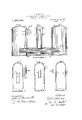
- ' Figure 1 is a vertical cross section of my generator.
- Fig. 2 is a vertical cross section of-another embodimentof my invention.
- Figs. 3, at and 5 are vertical cross sections through an explosion chamber showing various-meth-odsof utilizing my timing. device.-
- Fig. 6 isadiagrammatical plan view showing a plurality of pumps and power units connected to the high and low pressure tanks of my generator and the ignition system used therewith.
- FIG. 1 indicates the internal combustion pump, 2 the low pressure tank, 3 the high pressure tank, a a passage-connecting said tanks 2 and 3 and pump 1, and 5 a power unit connected to said high pressure tank 3 by pipe 6 and to low pressure tank 2 by pipe 7.
- Internal combustion pump 1 is fitted with any known ignition device as spark plug 8, and with any suitable fuel inlet valve'9, and exhaust 10, and an automatic timing device 11 hereinafter described in detail.
- Passage i is provided with an inlet valve 12 opening from low pressure tank 2, and an outlet valve 15 opening into high pressure tank 3.
- An automatic electric circuit closer is shown at 14 positioned in the wall of low pressure tank 2, although the same results as hereinafter described would be obtained if said circuitcloser lwere positioned in the wall of high pressure tank 3.
- valve 16 in the top of tank 3.
- These valves may be of any design that will permit the pumping of a fluid, such as air, 1111101311611 respective tanks.
- An inlet valve of ordinary type is indicated at 17, and a discharge valve is located at 18.
- An ordinary cut-01f valve is shown at 19 in pipe 6.
- In operating my generator the same is filled with a liquid through valve 17 to a I level with a discharge valve as 18, said level being indicated by line A, and an explosive mixture is admitted into pump 1 through intake valve 9.
- Intake valve 9 is supplied with a combustible mixture through any desirable mechanism not shown and is preferably of the reed type of valve.
- the vacuum followv ing the explosion in pump 1 therefore sucks by drawing'in a fresh combustible charge as described.
- the exhaust valve 10 being double headed is closed as shown when acted upon by a pressure within the pump and is closed from the outside when drawn shut by the creation of a partial vacuum within said pump.
- the liquid in low pressure tank 2 will be driven therefrom through valve 12 and into internal combustion pump 1 under a pressure of one hundred pounds, and the kinetic energy developed being upward of two hundred pounds will be suflicient to compress the ex plosive charge in said-pump which, when exploded, will force said liquid out through passage 4 and valve 13 vinto high pressure tank 3 with a pressure of upward of six hundred pounds, and of course still further compressing the compressible fluid contained therein.
- Valve 19 in pipe 6 being opened the liquid will now flow from high pressure tank 3' to low pressure tank 2 through said pipes 6 and 7, and any power unit that may be connected therebetween, thereby again nected to the contact devices in the follow ing manner.
- Electrode 22 is adjusted so that pin 21 cannot make contact with pin 23 when the pressure in tank 2 does not exceed one hundred pounds.
- a combustible mixture is now admitted into pump 1 through inlet valve 9 and the pressure in tanks 2 and 3 raised the necessary degree and said combustible mixture compressed as hereinbefore described, thereby closing contact device 11.
- the pressure being raised in' tank 2 to one hundred pounds or more diaphragm 20 will be forced outward and pin 21 caused to contact with pin 23, whereupon a current is caused to flow in the circuit above described and a spark produced in pump land the initial charge fired. It is now clear that as long as the pressure in tank 2 remains at or above a certain.
- each of said pumps is provided with a spark plug as indicated at SE8", 8 and 8 respectively and with a make-and-break device, preferably a diaphragm as hereinbefore described, and indicated at 11, 11", 11 and 11 respectively.
- the coils for the respective pumps are indicated at 32, 32 32 and 32 At 39 is indicated an insulated support earryin g an electrode 10 provided with a contact pin a'tl adapted to contact with pin in.
- Coil 32 is connected by high tension wiredo' to spark plug 8 in pump 35, and coils 32 32 and 32 being connected to spark plugs 8 8 and 8 in pumps 36, '37 and 38 by high tension wires d5, 45 and &5 respectively.
- Contact devices 11311 and 11 are connected to their respective coils 32, 32 and 32 by low tension wires ll, er and 44
- the contacts at 11, 11", 11 and 11 are designed to close only under explosion pressure when a plurality of pumps are used, therefore it is necessary to provide some means of firing the initial charge in pump This accomplished by means of electrode 40 and the parts connected thereto as above described, for when the pressure in tank 2 reaches the required. point dia fliragm 20 is pressed outward until pin 21 comes in contact with pin 23 and pin 42 comes in contact with pin %1.
- the electric current is now closed through coil 32 and a spark caused to pass in pum 35 igniting and exploding the charge therein;
- the forcing of liquid out of tank 2 and into tank 3 now causes the circuit to be broken at 11-42 (electrode 22 being a strong spring) but contact is maintained at 21-23 as long as the pressure in tank 2 is above a certain point, say one hundred pounds.
- the explosion in pump closes contact 11 which thereupon closes the circuit in which coil 32 is an element and thereby causes a spark to pass in pump 36 thus producing an explosion therein.
- explosion in pump 36 causes an explosion in pump 37, which is followed by an explosion in pump 33 in the same manner.
- any number of power units may be operatively connected between high and low pressure tanks 3 and 2 by connecting them with conduits connecting one tank with the other or connecting main conduits leading from said tanks.
- Fig. (3, 46 and 4:7 represent main conduits leading from tanks 3 and 2 respectively
- 48 and 1-9 are conduits connecting with main conduits 16 and 47 and having po "er units 50 and 51 respectively connected therein, the supply of power being regulated by valves 52 and respectively.
- Each power unit may thus be operated entirely independentlyvot' the other power units.
- a float operating contact device as shown at 28 may be. used or an intake valve operated arm may be used as shown at 29 for firing the charges in the adjoining pump. It will be seen from the foregoing that the generator operates in an automatic manner, pump 1 continuing to keep the pressure in tank 3 at a predetermined point automatically.
- the explosion controlling device shown mounted on tank 2 it may be mounted on tank 3, or it may be a float actuated by the rise and fall of the liquid in the tanks without departing -from the spirit of the invention.
- the explosions instead of being interruptedas herein described may be reduced in volume as in a throttling engine, and a bypass conduit as 5 may be used between tanks 2 and 3 to allow enougl'i liquid to pass "from tank 3 to tank 2 to allow the generator to continue in operation under reduced fuel charges, but it is preferable that it should operate in the manner herein described for high economy.
- .my power generator When .my power generator is used as shown in Fig. 2 there is no power unit positioned between high pressure tank 3 and low pressure tank 2 but the liquid used as a driving means for a power unit or mechanism of any kind is discharged from high pressure tank 3 through an outlet pipe as 25. To compensate for the liquid discharged at 25, an amount of liquid equal to that discharged is introduced through pipe 26 into low pressure tank 2. This liquid is introduced by means of an injector 27 connected to high pressure tank 3, so that the amount of liquid in the generator will be a predetermined qu'antity whether the generator is operating or not.
- a generator of this type may be used for driving ships by hydraulic force or for raising water by the injector method.
- the method of generating power which consists in subjecting a body of liquid to an elastic fluid pressure of 50 lbs. or more, utilizing the elastic pressure to force liquid into explosion chambers'thereby compressing combustible mixtures therein, utilizing the energy of the expanding charge when exploded to induce fresh combustible mixtures and to force liquid into a second body of liquid under an elastic fluid pressure of 100 lbs. or more and utilizing the elastic pressure of said second body of liquid to force liquid through power transmitting devices and to replenish said first body of liquid.
- the method of generating power which consists in subjecting a body of liquid to an elastic fluid pressure, utilizing the elastic pressure to force liquid into an explosion chamber thereby compressing a combustible mixture therein, utilizing the energy of the expanding charge when exploded to induce a. fresh combustible mixture and to force a second body of liquid to a higher elastic pressure, and utilizing said higher elastic pressure of said second body of liquid to force liquid through power transmitting de vices into said first body of liquid and to force liquid directly into said first body of liquid.
- the method of generating power which consists in subjecting a body of liquid to an elastic fluid pressure, utilizing theelastic pressure to force liquid into explosion chambers thereby causing self ignition of the combustible charge contained therein, utilizing the energy of the expanding charge when exploded to induce fresh combustible mixtures and to force a second body of liquid to a higher elastic fluid pressure, and utilizing said higher elastic fluid pressure of said second body of liquid to force'liquid through power transmitting devices and to replenish said first body of liquid.
- the herein described method of gen erating power which consists in subjecting a body of liquid to an elastic fluid pressure, utilizing the elastic pressure to force liquid into explosion chambers, thereby compressing combustible mixtures therein, utilizing the energy of the expanding charge when exploded to induce a fresh combustible mixture and to force a second body of liquid to a higher elastic pressure, and utilizing said high elastic pressure of said second body of liquid to force liquid through power transmitting devices and to replenish said first body of liquid.
- the herein described method of generating power which consists in connecting a plurality of explosion chambers to a high and a low pressure tank, subjecting the liquid in the low pressure tank to an elastic fluid pressure sufficient to force it into said explosion chambers thereby compressing explosive mixtures contained therein and to close an ignition circuit thereby exploding the explosive mixture in one explosion chamber, and thereafter utilizing the energy of the expanding charge in each explosion chamber to close an ignition circuit and thereby explode the explosive mixture in another explosion chamber and to force liquid through power transmitting devices before the return of said liquid to said explosion chambers.
- the method of generating power which consists in subjecting a body of liquid to an elastic fluid pressureof 50 lbs. or more, utilizing the elastic pressure to force liquid into explosion chambers thereby compressing combustible mixtures therein, utilizing the energy of the expanding charge when exploded to force liquid into'a second body of liquid under an elastic fluid pressure of affixed my signature in presence of two sub- 100 lbs. 01% more and utilizing fthe elastic scribing Witnesses.
- pressure 0 said second 0d 0 liquid to 7 force liquid through power tr insrnitting de- PONTUS OSTENBERG' vices and to replenish said first body of l/Vitnesses: liquid.
- JOHN A. NAISMITH
Landscapes
- Engineering & Computer Science (AREA)
- Mechanical Engineering (AREA)
- General Engineering & Computer Science (AREA)
- Reciprocating Pumps (AREA)
Description
P. OSTENBERG.
EXPLOSIVE METHOD OF GENERATING POWER.
APPLICATION FILED JAN-28.19%.
1,237,688., Patented Aug. 21, 1917.
3 SHEETS-SHEET I.
wmawmzw Av \A/ITNESSESZ H' ATT RN Y P. OSTENBERG.
EXPLOSIYE METHOD OF GENERATING POWER.
APPLlCATlON FILED JAN-28,1915.
Patented Aug. 21, 1917.
3 SHEETSSHEET 2.
1 ATT RN Y WEQWE FEGRJE 5 P. OSTENBERG.
EXPLOSIV'E METHOD OF GENERATINQPOWER. APPLICATION FILED JAN.28. 1915.
3 SHEETS-SHEET 3.
EHGEJEE 6 \A/FHN'ESSES Patented Aug. 21, 1917.
PONTUS OSTENBERG, OF LOS GATOS, CALIFORNIA.
EXPLOSIVE METHOD OF GENERATING POWER.
To all whom it may concern.-
Be it known that I, PONTUS OSTENBERG, a citizen of the United States, and a resident of Los Gatos, in the county of Santa Clara and State of California, have invented a, certain new and useful Improvement in Ex,- plosive Methods of Generating ,Power, of which the following is a specification.
My inventionrelates to improvements in explosive method of generating power in which the expansion of-a compressed and ignited combustible mixture of air and fuel is used in combination with a non-compressible liquid under. a high elastic fluid pressure.
The object of my invention is to produce a power gene 'ator of great simplicity, light in weight per given horsepower, and the utilization of a high elastic fluid pressure within the generator to produce ahigh compression and rapid induction of liquid into the explosion chambers of the generator, and to provide means for controlling such a generator automatically.
The present inventlon differs from other power generating methods which employ liquids as a propelling agent in combination with explosions of combustible mixtures from the factthat such usea rapid reciproe cation or high velocity of the liquid to produce a compression in the explosion chambers of the generator. It also differs. from other generators which compress an air cushion during the power stroke and which induces compression upon the return stroke from the fact that the elastic pressure in the present invention not only contracts and expands somewhat'with the explosions, but falls and rises when liquid is allowed to flow in the circuit. In my invention a high compression is produced by a high elastic fluid pressure, such as air or gas, forcing liquid into the explosion chambers of the generator. I also control the explosions in an automatic manner by the pressures from within the generator as-will be more fully described herein.
In generating power in the manner herein described, I utilize a liquid operating in a;
closed circuit undera high fluid pressure, said circuit comprising a low pressure tank and ahigh pressure tank, {IllulIltBIIlitl comspecification of Letters Patent. Patented A 0; 21 1917.
Application filed January 28,1915; Serial No. 4,880.
bustion pump, and a power transmitting medium. I further contemplate using the pressures of theexplosions and the system for closing electric circuits and timing the 'ex- 7 plosions in the explosion chambers of the generator, and also .to utilize the pressures in either of the above mentioned tanks for automatically. closing the timing circuit when the pressure therein rises above a specifiedpoint, and. to break said circuit when said pressure falls below said point." I further contemplate adapting my generator for i several .vicws,
'Figure 1 is a vertical cross section of my generator.
. Fig. 2 is a vertical cross section of-another embodimentof my invention.
Figs. 3, at and 5, are vertical cross sections through an explosion chamber showing various-meth-odsof utilizing my timing. device.-
Fig. 6 isadiagrammatical plan view showing a plurality of pumps and power units connected to the high and low pressure tanks of my generator and the ignition system used therewith.
In the drawings 1 indicates the internal combustion pump, 2 the low pressure tank, 3 the high pressure tank, a a passage-connecting said tanks 2 and 3 and pump 1, and 5 a power unit connected to said high pressure tank 3 by pipe 6 and to low pressure tank 2 by pipe 7. Internal combustion pump 1,is fitted with any known ignition device as spark plug 8, and with any suitable fuel inlet valve'9, and exhaust 10, and an automatic timing device 11 hereinafter described in detail. Passage i is provided with an inlet valve 12 opening from low pressure tank 2, and an outlet valve 15 opening into high pressure tank 3. An automatic electric circuit closer is shown at 14 positioned in the wall of low pressure tank 2, although the same results as hereinafter described would be obtained if said circuitcloser lwere positioned in the wall of high pressure tank 3. A valve 15. is shown in thetop of tank! anda valve 16 in the top of tank 3. These valves may be of any design that will permit the pumping of a fluid, such as air, 1111101311611 respective tanks. An inlet valve of ordinary type is indicated at 17, and a discharge valve is located at 18. An ordinary cut-01f valve is shown at 19 in pipe 6.
In operating my generator the same is filled with a liquid through valve 17 to a I level with a discharge valve as 18, said level being indicated by line A, and an explosive mixture is admitted into pump 1 through intake valve 9. Intake valve 9 is supplied with a combustible mixture through any desirable mechanism not shown and is preferably of the reed type of valve. The vacuum followv ing the explosion in pump 1 therefore sucks by drawing'in a fresh combustible charge as described. The exhaust valve 10 being double headed is closed as shown when acted upon by a pressure within the pump and is closed from the outside when drawn shut by the creation of a partial vacuum within said pump. WV hen, however, a fresh charge has been drawn into pump 1 and the liquid starts to return into said pump due to the pressure from tank 2, then the spring-like action of the inner member of valve 10 serves to hold said valve open for the exhaust of burnt gases until the rising liquid shuts the same,valve 9 having closed when the pressure within the pump approximated atmospheric pressure. The compressible fluid asair, in tank 2 is now pumped to a pressure of one hundred pounds or more through valve 15,, and the compressible fluid in tank 3 is pumped to a pressure of two-hundred pounds or more through valve 16,'the figures of course only indicating the approximate relative pressures in said two tanks. The liquid in low pressure tank 2 will be driven therefrom through valve 12 and into internal combustion pump 1 under a pressure of one hundred pounds, and the kinetic energy developed being upward of two hundred pounds will be suflicient to compress the ex plosive charge in said-pump which, when exploded, will force said liquid out through passage 4 and valve 13 vinto high pressure tank 3 with a pressure of upward of six hundred pounds, and of course still further compressing the compressible fluid contained therein. Valve 19 in pipe 6 being opened the liquid will now flow from high pressure tank 3' to low pressure tank 2 through said pipes 6 and 7, and any power unit that may be connected therebetween, thereby again nected to the contact devices in the follow ing manner. 20 is a diaphragm positioned v in the wall of tank 2 and having a projecting pin 21 secured to the outer surface thereof. Secured to the, outer surface of tank'2 and insulated therefrom is an electrode 22 having a pin 23 secured thereto in such a position as to engage pin 21 when diaphragm 20 is pressed outward, said electrode' 22-being connected with the battery 30 by wire 24. Battery 30 is connected tocoil 32 by lowtension wire 31, and coil 32 is connected to contact device 11 in pump 1 by low tension wire 41. At l5is indicated a high tension wire connecting coil 32 to spark plug 8. In operation this device works as follows: Electrode 22 is adjusted so that pin 21 cannot make contact with pin 23 when the pressure in tank 2 does not exceed one hundred pounds. A combustible mixture is now admitted into pump 1 through inlet valve 9 and the pressure in tanks 2 and 3 raised the necessary degree and said combustible mixture compressed as hereinbefore described, thereby closing contact device 11. The pressure being raised in' tank 2 to one hundred pounds or more diaphragm 20 will be forced outward and pin 21 caused to contact with pin 23, whereupon a current is caused to flow in the circuit above described and a spark produced in pump land the initial charge fired. It is now clear that as long as the pressure in tank 2 remains at or above a certain. point the ignition circuit is closed at contact 2123 but remains open at con tact device 11 until the pressure in pump 1 is sufficiently raised to close the same whereupon the entire ignition circuit is closed and a spark ensues that fires the charge in pump 1, the resulting discharge of liquid from the pump lowering the pressure therein and breaking the ignition c1rcuit at contact device 11 until the incomin g liquid again raises the pressure sufficiently to close the same. If no method of breaking the main circuit is provided the motor would soon blow itself to pieces as it would be working under higher and higher compression. With a make and break device as shown at 2122 an explosion cannot occurin pump 1 until the pressure exceeds a certain amount in chamber 2. For instance, if itis-desired to drive power unit 5 at a low speed the supply through pipe 6 is reduced by valve 19. Then explosions will ocour in pump '1 untilthe liquid in chamber 3 is under great pressure and the liquid in chamber 2 under low pressure so'that main circuit closed at 21 22 and an initial spark produced in, pump 1 causing the first explosion. The main circuit being closed ignition device 11 will cause explosions at the proper intervals until said main circuit is again broken at 2122 and the pressure in tank 3 allowed to decrease and the pressure in tank 2 to increase as hereinbefore described. The ignition means, when a plurality of pumps are used, is connected and operated as follows. Assuming that four pumps 35, 36, 37 and 38 respectively are-connected by their respectivepassagesetfl 1 and 1 to low pressure tank 2 andhigh pressure tank as hereinbetore described, power units 50 and 51 being connected to high pressure tank 3 by pipes l8 and are respectively, and to low pressure tank 2-by pipes t8 and as. Each of said pumps is provided with a spark plug as indicated at SE8", 8 and 8 respectively and with a make-and-break device, preferably a diaphragm as hereinbefore described, and indicated at 11, 11", 11 and 11 respectively. The coils for the respective pumps are indicated at 32, 32 32 and 32 At 39 is indicated an insulated support earryin g an electrode 10 provided with a contact pin a'tl adapted to contact with pin in. arm 22 when diaphragm 20 is forced out,- ward by the pressure intank Arm to is connected by wire e3 to wire i l which is in turn connected to coil 32 and contact device 11 in pump 38. Coil 32 is connected by high tension wiredo' to spark plug 8 in pump 35, and coils 32 32 and 32 being connected to spark plugs 8 8 and 8 in pumps 36, '37 and 38 by high tension wires d5, 45 and &5 respectively. Contact devices 11311 and 11 are connected to their respective coils 32, 32 and 32 by low tension wires ll, er and 44 The contacts at 11, 11", 11 and 11 are designed to close only under explosion pressure when a plurality of pumps are used, therefore it is necessary to provide some means of firing the initial charge in pump This accomplished by means of electrode 40 and the parts connected thereto as above described, for when the pressure in tank 2 reaches the required. point dia fliragm 20 is pressed outward until pin 21 comes in contact with pin 23 and pin 42 comes in contact with pin % 1. The electric current is now closed through coil 32 and a spark caused to pass in pum 35 igniting and exploding the charge therein; The forcing of liquid out of tank 2 and into tank 3 now causes the circuit to be broken at 11-42 (electrode 22 being a strong spring) but contact is maintained at 21-23 as long as the pressure in tank 2 is above a certain point, say one hundred pounds. The explosion in pump closes contact 11 which thereupon closes the circuit in which coil 32 is an element and thereby causes a spark to pass in pump 36 thus producing an explosion therein. The
explosion in pump 36 causes an explosion in pump 37, which is followed by an explosion in pump 33 in the same manner. (7ontact 11 in pump 38 being connected by low tension wire ell to coil 32 which in turn is connected by high tension wire 15 to spark plug 8 of pump 05, the explosion in pump 38 must cause an explosion in pump 35 and so on, so that the pumps must operate in rapid succession as long as the pressure in tank. 2 is sutlicient to keepthe ignition circuit closed at 2123. lV hen the circuit is broken at 21'23.'the pumps will cease to operate but will automatically start again the moment said circuit is again closed at 21-23 and'll-tl2. Any number of power units may be operatively connected between high and low pressure tanks 3 and 2 by connecting them with conduits connecting one tank with the other or connecting main conduits leading from said tanks. lln Fig. (3, 46 and 4:7 represent main conduits leading from tanks 3 and 2 respectively, and 48 and 1-9 are conduits connecting with main conduits 16 and 47 and having po "er units 50 and 51 respectively connected therein, the supply of power being regulated by valves 52 and respectively. Each power unit may thus be operated entirely independentlyvot' the other power units. Instead of using the timing device shown at 11, a float operating contact device as shown at 28 may be. used or an intake valve operated arm may be used as shown at 29 for firing the charges in the adjoining pump. It will be seen from the foregoing that the generator operates in an automatic manner, pump 1 continuing to keep the pressure in tank 3 at a predetermined point automatically.
While the explosion controlling device shown mounted on tank 2 it may be mounted on tank 3, or it may be a float actuated by the rise and fall of the liquid in the tanks without departing -from the spirit of the invention. Also the explosions instead of being interruptedas herein described, may be reduced in volume as in a throttling engine, and a bypass conduit as 5 may be used between tanks 2 and 3 to allow enougl'i liquid to pass "from tank 3 to tank 2 to allow the generator to continue in operation under reduced fuel charges, but it is preferable that it should operate in the manner herein described for high economy.
When .my power generator is used as shown in Fig. 2 there is no power unit positioned between high pressure tank 3 and low pressure tank 2 but the liquid used as a driving means for a power unit or mechanism of any kind is discharged from high pressure tank 3 through an outlet pipe as 25. To compensate for the liquid discharged at 25, an amount of liquid equal to that discharged is introduced through pipe 26 into low pressure tank 2. This liquid is introduced by means of an injector 27 connected to high pressure tank 3, so that the amount of liquid in the generator will be a predetermined qu'antity whether the generator is operating or not. A generator of this type may be used for driving ships by hydraulic force or for raising water by the injector method.
lVhile I have described my invention in the form which I consider best adapted to generate power in the method described, I
do not restrict myself to details of construction as these may be modified or varied in many ways without departing from the principles of the invention. I also contemplate usingpressures from a few pounds to pressures sufficient to ignite heavy fuels by self ignition as inthe Diezel engine, in which case the sparking devices may be removed.
Having thus described my invention, what I claim as new and desire to secure by Let ters Patent, is
l. The method of generating power which consists in subjecting a body of liquid to an elastic fluid pressure of 50 lbs. or more, utilizing the elastic pressure to force liquid into explosion chambers'thereby compressing combustible mixtures therein, utilizing the energy of the expanding charge when exploded to induce fresh combustible mixtures and to force liquid into a second body of liquid under an elastic fluid pressure of 100 lbs. or more and utilizing the elastic pressure of said second body of liquid to force liquid through power transmitting devices and to replenish said first body of liquid.
2. The method of generating power which consists in subjecting a body of liquid to an elastic fluid pressure, utilizing the elastic pressure to force liquid into an explosion chamber thereby compressing a combustible mixture therein, utilizing the energy of the expanding charge when exploded to induce a. fresh combustible mixture and to force a second body of liquid to a higher elastic pressure, and utilizing said higher elastic pressure of said second body of liquid to force liquid through power transmitting de vices into said first body of liquid and to force liquid directly into said first body of liquid.
The method of generating power which consists in subjecting a body of liquid to an elastic fluid pressure, utilizing theelastic pressure to force liquid into explosion chambers thereby causing self ignition of the combustible charge contained therein, utilizing the energy of the expanding charge when exploded to induce fresh combustible mixtures and to force a second body of liquid to a higher elastic fluid pressure, and utilizing said higher elastic fluid pressure of said second body of liquid to force'liquid through power transmitting devices and to replenish said first body of liquid.
4. The herein described method of gen erating power which consists in subjecting a body of liquid to an elastic fluid pressure, utilizing the elastic pressure to force liquid into explosion chambers, thereby compressing combustible mixtures therein, utilizing the energy of the expanding charge when exploded to induce a fresh combustible mixture and to force a second body of liquid to a higher elastic pressure, and utilizing said high elastic pressure of said second body of liquid to force liquid through power transmitting devices and to replenish said first body of liquid.
5. The herein described method of gen erating power; which consists in subjecting a body of liquid to an elastic fluid pressure,
i' tilizing said elastic fluid pressure to force liquid into explosion chambers thereby comiressing the explosive mixture contained therein, and to close an electric circuit thereby exploding the explosive mixture in one of said explosion chambers, utilizing the energy of the expanding charge through the liquid medium on power transmitting devices before the return of said liquid to the explosion chamber and to close an electric circuit thereby exploding an explosive mixture in another explosion chamber.
6. The herein described method of generating power which consists in connecting a plurality of explosion chambers to a high and a low pressure tank, subjecting the liquid in the low pressure tank to an elastic fluid pressure sufficient to force it into said explosion chambers thereby compressing explosive mixtures contained therein and to close an ignition circuit thereby exploding the explosive mixture in one explosion chamber, and thereafter utilizing the energy of the expanding charge in each explosion chamber to close an ignition circuit and thereby explode the explosive mixture in another explosion chamber and to force liquid through power transmitting devices before the return of said liquid to said explosion chambers.
7. The method of generating power which consists in subjecting a body of liquid to an elastic fluid pressureof 50 lbs. or more, utilizing the elastic pressure to force liquid into explosion chambers thereby compressing combustible mixtures therein, utilizing the energy of the expanding charge when exploded to force liquid into'a second body of liquid under an elastic fluid pressure of affixed my signature in presence of two sub- 100 lbs. 01% more and utilizing fthe elastic scribing Witnesses. pressure 0 said second 0d 0 liquid to 7 force liquid through power tr insrnitting de- PONTUS OSTENBERG' vices and to replenish said first body of l/Vitnesses: liquid. JOHN A. NAISMITH,
In testimony whereof I have hereunto CLARENCE A. NAISMITH.
Copies of this patent may be obtained for five cents each, by addressing the Commissioner of Patents, Washington, I). O.
Priority Applications (1)
| Application Number | Priority Date | Filing Date | Title |
|---|---|---|---|
| US488015A US1237688A (en) | 1915-01-28 | 1915-01-28 | Explosive method of generating power. |
Applications Claiming Priority (1)
| Application Number | Priority Date | Filing Date | Title |
|---|---|---|---|
| US488015A US1237688A (en) | 1915-01-28 | 1915-01-28 | Explosive method of generating power. |
Publications (1)
| Publication Number | Publication Date |
|---|---|
| US1237688A true US1237688A (en) | 1917-08-21 |
Family
ID=3305506
Family Applications (1)
| Application Number | Title | Priority Date | Filing Date |
|---|---|---|---|
| US488015A Expired - Lifetime US1237688A (en) | 1915-01-28 | 1915-01-28 | Explosive method of generating power. |
Country Status (1)
| Country | Link |
|---|---|
| US (1) | US1237688A (en) |
Cited By (2)
| Publication number | Priority date | Publication date | Assignee | Title |
|---|---|---|---|---|
| US4045830A (en) * | 1974-03-27 | 1977-09-06 | Societe Nationale Des Poudres Et Explosifs | System of protection by modeling |
| US4515500A (en) * | 1983-11-15 | 1985-05-07 | Ecopool Design Limited | Combustion powered wave generator |
-
1915
- 1915-01-28 US US488015A patent/US1237688A/en not_active Expired - Lifetime
Cited By (2)
| Publication number | Priority date | Publication date | Assignee | Title |
|---|---|---|---|---|
| US4045830A (en) * | 1974-03-27 | 1977-09-06 | Societe Nationale Des Poudres Et Explosifs | System of protection by modeling |
| US4515500A (en) * | 1983-11-15 | 1985-05-07 | Ecopool Design Limited | Combustion powered wave generator |
Similar Documents
| Publication | Publication Date | Title |
|---|---|---|
| US1237688A (en) | Explosive method of generating power. | |
| US3867812A (en) | Gas motor power system | |
| US125166A (en) | Improvement in gas-engines | |
| US1137328A (en) | Internal-combustion generator. | |
| US1120828A (en) | Fuel-supply system and starter for explosive-engines. | |
| US1811654A (en) | Internally fired heat or power generator | |
| US292546A (en) | dieckmann | |
| US587375A (en) | siddle | |
| US1156534A (en) | Heat-engine. | |
| US1608446A (en) | District of | |
| US1131082A (en) | Vacuum-producing apparatus. | |
| US1416867A (en) | Power-generating system | |
| US1259338A (en) | Internal-combustion hydraulic pump. | |
| US1633502A (en) | Control system for liquid-fuel burners | |
| US1158303A (en) | Internal-combustion pump. | |
| US1516006A (en) | Pump | |
| US956465A (en) | Pressure-generator. | |
| US321929A (en) | Steam-boiler | |
| US807569A (en) | Explosion-motor. | |
| US1605773A (en) | Art of generating power | |
| US1279514A (en) | Steam-generator. | |
| US278257A (en) | Hot aie and gas engine | |
| US1361648A (en) | Internal-combustion engine | |
| US1122796A (en) | Steam-generator. | |
| US1154034A (en) | Engine. |