US123764A - Improvement in valves for direct-acting engines - Google Patents
Improvement in valves for direct-acting engines Download PDFInfo
- Publication number
- US123764A US123764A US123764DA US123764A US 123764 A US123764 A US 123764A US 123764D A US123764D A US 123764DA US 123764 A US123764 A US 123764A
- Authority
- US
- United States
- Prior art keywords
- piston
- ports
- valve
- motive
- valves
- Prior art date
- Legal status (The legal status is an assumption and is not a legal conclusion. Google has not performed a legal analysis and makes no representation as to the accuracy of the status listed.)
- Expired - Lifetime
Links
Images

Classifications
-
- F—MECHANICAL ENGINEERING; LIGHTING; HEATING; WEAPONS; BLASTING
- F15—FLUID-PRESSURE ACTUATORS; HYDRAULICS OR PNEUMATICS IN GENERAL
- F15B—SYSTEMS ACTING BY MEANS OF FLUIDS IN GENERAL; FLUID-PRESSURE ACTUATORS, e.g. SERVOMOTORS; DETAILS OF FLUID-PRESSURE SYSTEMS, NOT OTHERWISE PROVIDED FOR
- F15B11/00—Servomotor systems without provision for follow-up action; Circuits therefor
- F15B11/02—Systems essentially incorporating special features for controlling the speed or actuating force of an output member
- F15B11/04—Systems essentially incorporating special features for controlling the speed or actuating force of an output member for controlling the speed
- F15B11/046—Systems essentially incorporating special features for controlling the speed or actuating force of an output member for controlling the speed depending on the position of the working member
- F15B11/048—Systems essentially incorporating special features for controlling the speed or actuating force of an output member for controlling the speed depending on the position of the working member with deceleration control
-
- B—PERFORMING OPERATIONS; TRANSPORTING
- B24—GRINDING; POLISHING
- B24B—MACHINES, DEVICES, OR PROCESSES FOR GRINDING OR POLISHING; DRESSING OR CONDITIONING OF ABRADING SURFACES; FEEDING OF GRINDING, POLISHING, OR LAPPING AGENTS
- B24B47/00—Drives or gearings; Equipment therefor
- B24B47/02—Drives or gearings; Equipment therefor for performing a reciprocating movement of carriages or work- tables
- B24B47/06—Drives or gearings; Equipment therefor for performing a reciprocating movement of carriages or work- tables by liquid or gas pressure only
Definitions
- My invention relatesto an lmproved arrangement of valves and ports in direct-acting engines for the purpose of obtaining a perfectly sure and regular movement, and overcoming difliculties heretofore experienced in this class of engines, particularly in the variety known as automatic, -usually applied to steampumps.
- a main slide-valve moved by a piston which is operated by steam let on by the action of an auxiliary valve which is moved directly by the main piston.
- My improvements consist in arranging the main slide-valve upon a movable seat, which is itself a valve, andis provided with suitable ports, so that it may operate as the main valve of the engine under certain circumstances when the ordinary valve would fail; and further, in certain improvements in the arrangement of the auxiliary valve and ports,
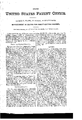
- Figure I is a general section of the upper part of the steam-cylinder showing the valves and ports.
- Fig. II is a plan view of the movable seat without its ports.
- Figs. III and IV are diagrams showing the arrangement of the auxiliary valve and ports.
- the upper face of the movable Seat 0 is an ranged to form the seat of the valve B.
- the lower face also seats upon. the upper part of the main cylinder containing the ports f g h.
- the auxiliary valve for opera-ting the motive piston I prefer to construct upon and forming a part of the movable seat 0, as shown in Figs. II, III, IV, which I will now describe.
- wings m n On each side of the main body M of the movable Seat I arrange wings m n, one having ports arranged to let Steam on to the ends of the motive pistonA, and cut it ofl therefrom at proper times, shown at Fig. IV; the other provided with ports operating to exhaust steam from the plunger or motive piston, as shown .at Fig. III.
- the movable seat 0 acts as the main valve of the engine, for by the passage of the same over its ports steam is admitted by the passage of the bridge 1) or p beyond the end of the seat, admitting steam into the port 0 or e.
- III, IV is as follows: Steam is admitted by the passage of the port 0 over one of the small ports 8 t to one end of the cylinder containing the motive piston A, while at the same time it is exhausted from the opposite end of the motive-piston cylinder, by the passage of one of the ports 1) w over one of the Small ports as y, the ports 2; w communicating directly with the exhaust-port of the movable seat 0, and the ports a: y communicating with the ends of the motive-piston cylinder, as shown.
- the entrance of the small exhaust-passages w y with the cylinder of the motive piston is at uch a point, that the motive piston passes over and cuts off the same for the purpose of cushioning.
- the motive piston shall not carry over "its valve with sufficient.rapidity to prevent the main piston striking on its cylinder-head.
- the direct action of the piston of the engine carries the movable seat over so far that steam is admitted into the port 0 or the port 0, as before mentioned, and thus the piston is prevented from striking the head as the steam thus admitted cushions and arrests the motion of the piston before it has arrived at the end of the cylinder; and further, by the movement of this movable seat or valve 0 the ingoing steam is cut off at a point much earlier in the stroke than it would be if controlled by the plunger-valve only, thus slowing the main piston near the end of its stroke.
- the auxiliary valve shall be of the construction described, although I prefer it nor is it essential that it be on the plane of the main valve or even in the same valvechest.
- a movable valve-seat provided with ports, arranged to operate in connection with the ordinary valve of the engine, substantially as set forth.
- the wings m n arranged on both sides of the main valve, for the purpose of containing ports and bridges for operating the plunger or motive piston A.
- valve arrangement having a movable seat, as shown, the combination, with the said seat, of the secondary or auxiliary valve to operate the plunger or motive piston.
- A the same consisting of two wings attached to or forming a part of the movable seat, and operating to let on steam to the motive piston and exhaust the same independently, as specified.
Landscapes
- Engineering & Computer Science (AREA)
- Mechanical Engineering (AREA)
- Physics & Mathematics (AREA)
- Fluid Mechanics (AREA)
- General Engineering & Computer Science (AREA)
- Lift Valve (AREA)
Description
GEORGE F. BLAKE.
Improvement in Valves of Direct ActingEngins.
NO.123,764. Patente d Feb. 20,1872.
I m m Ill fig]
[In/em; r m I I AM. PII'UI 'LITHOMAPIIIC M Ill/0313 QIPIVE} PIPILIJ'I/ UNITED STATES PATENT OFFICE.
cEoEeE F. BLAKE, or BOSTON, MAsSAoEUSETT's.
IMPROVEMENT IN VALVES FOR DIRECT-ACTING ENGINES.
' Specification forming part of Letters Patent No. 123,764, dated February 20, 1872.
N ature and Object of Invention.
My invention relatesto an lmproved arrangement of valves and ports in direct-acting engines for the purpose of obtaining a perfectly sure and regular movement, and overcoming difliculties heretofore experienced in this class of engines, particularly in the variety known as automatic, -usually applied to steampumps. In such engines it is common to use a main slide-valve moved by a piston, which is operated by steam let on by the action of an auxiliary valve which is moved directly by the main piston. My improvements consist in arranging the main slide-valve upon a movable seat, which is itself a valve, andis provided with suitable ports, so that it may operate as the main valve of the engine under certain circumstances when the ordinary valve would fail; and further, in certain improvements in the arrangement of the auxiliary valve and ports,
v and in the construction of the motive piston or plunger.
In the accompanying drawing, Figure I is a general section of the upper part of the steam-cylinder showing the valves and ports. Fig. II is a plan view of the movable seat without its ports. Figs. III and IV are diagrams showing the arrangement of the auxiliary valve and ports.
General Description.
The upper face of the movable Seat 0 is an ranged to form the seat of the valve B. The lower face also seats upon. the upper part of the main cylinder containing the ports f g h. The auxiliary valve for opera-ting the motive piston, I prefer to construct upon and forming a part of the movable seat 0, as shown in Figs. II, III, IV, which I will now describe. On each side of the main body M of the movable Seat I arrange wings m n, one having ports arranged to let Steam on to the ends of the motive pistonA, and cut it ofl therefrom at proper times, shown at Fig. IV; the other provided with ports operating to exhaust steam from the plunger or motive piston, as shown .at Fig. III.
, Operation. In the event of any failure of the main valve B to move with suflicient rapidity to reverse the motion of the main piston before it shall have arrived at the end of the cylinder, the movable seat 0 acts as the main valve of the engine, for by the passage of the same over its ports steam is admitted by the passage of the bridge 1) or p beyond the end of the seat, admitting steam into the port 0 or e. The action of the auxiliary valve shown in Figs. III, IV, is as follows: Steam is admitted by the passage of the port 0 over one of the small ports 8 t to one end of the cylinder containing the motive piston A, while at the same time it is exhausted from the opposite end of the motive-piston cylinder, by the passage of one of the ports 1) w over one of the Small ports as y, the ports 2; w communicating directly with the exhaust-port of the movable seat 0, and the ports a: y communicating with the ends of the motive-piston cylinder, as shown. The entrance of the small exhaust-passages w y with the cylinder of the motive piston is at uch a point, that the motive piston passes over and cuts off the same for the purpose of cushioning. By this division of the steam and exhaust communications operating independently of each other, I am able to use free-entrance ports with the motive-piston cylinder, while at the same time all purposes of cushionin g are equally well served. In all usual cases the operation of the main piston upon the movable seat with its auxiliary valves will cause the motive piston to reverse the engine,
as will be seen by the foregoing description; but we will suppose that by reason of high velocity of the main piston or other cause, the motive piston shall not carry over "its valve with sufficient.rapidity to prevent the main piston striking on its cylinder-head. In such, the direct action of the piston of the engine carries the movable seat over so far that steam is admitted into the port 0 or the port 0, as before mentioned, and thus the piston is prevented from striking the head as the steam thus admitted cushions and arrests the motion of the piston before it has arrived at the end of the cylinder; and further, by the movement of this movable seat or valve 0 the ingoing steam is cut off at a point much earlier in the stroke than it would be if controlled by the plunger-valve only, thus slowing the main piston near the end of its stroke. It is not essential to the operation of the movable seat and other ports that the auxiliary valve shall be of the construction described, although I prefer it nor is it essential that it be on the plane of the main valve or even in the same valvechest.
I claim 1. A movable valve-seat provided with ports, arranged to operate in connection with the ordinary valve of the engine, substantially as set forth.
2. The wings m n arranged on both sides of the main valve, for the purpose of containing ports and bridges for operating the plunger or motive piston A.
3. The arrangement of the port 0 and bridges 1 2, operating in connection with ports 8 t, for the purpose of letting on steam to move the motive piston and cutting off the same therefrom at proper times.
4. The arrangement of .two ports 4) w and bridges 5 6 7, operating in. connection with ports 00 y, to control the exhaust from the motive piston.
5. In a valve arrangement having a movable seat, as shown, the combination, with the said seat, of the secondary or auxiliary valve to operate the plunger or motive piston. A, the same consisting of two wings attached to or forming a part of the movable seat, and operating to let on steam to the motive piston and exhaust the same independently, as specified.
6. I also claim the combination, with the movable seat, of a single slide of ordinary construction when forming a part of the movable seat, as described.
The foregoing specification signed and Witnessed at Washington this 9th day of June, A. D. 1871.
.- GEO. F. BLAKE. WVitnesses:
CHAS F. SrANs URY,
E. R. STANsBURY.
Publications (1)
| Publication Number | Publication Date |
|---|---|
| US123764A true US123764A (en) | 1872-02-20 |
Family
ID=2193198
Family Applications (1)
| Application Number | Title | Priority Date | Filing Date |
|---|---|---|---|
| US123764D Expired - Lifetime US123764A (en) | Improvement in valves for direct-acting engines |
Country Status (1)
| Country | Link |
|---|---|
| US (1) | US123764A (en) |
-
0
- US US123764D patent/US123764A/en not_active Expired - Lifetime
Similar Documents
| Publication | Publication Date | Title |
|---|---|---|
| US123764A (en) | Improvement in valves for direct-acting engines | |
| US123174A (en) | Improvement in valves for steam-engines | |
| US400374A (en) | Valve for locomotives | |
| US261485A (en) | Steam-actuated valve | |
| US265226A (en) | garrison | |
| US818284A (en) | Fluid-actuated valve. | |
| US118692A (en) | Improvement in steam-engines | |
| US380888A (en) | Steam-actuated valve | |
| US726871A (en) | Double-cylinder sinking-pump. | |
| US123765A (en) | Improvement in valves for direct-acting engines | |
| US334108A (en) | Steam-actuated valve | |
| US82936A (en) | Improvement in steam-engine-piston valves | |
| US749170A (en) | Ko model | |
| US112684A (en) | Improvement in steam-valves | |
| US132120A (en) | Improvement in steam-valves | |
| US691161A (en) | Compound-engine valve. | |
| US1177588A (en) | Engine-valve. | |
| US252084A (en) | Direct-acting engine | |
| US824903A (en) | Automatic equalizing piston-valve. | |
| US91368A (en) | Improvement in valves and opening for steam-engines | |
| US431180A (en) | Duplex valve for pumping-engines | |
| US335571A (en) | Engine-valve | |
| US167408A (en) | Improvement in direct-acting ewgines | |
| US812353A (en) | Steam-engine. | |
| US327902A (en) | Teeeitoey |