US1237625A - Object-throwing machine. - Google Patents
Object-throwing machine. Download PDFInfo
- Publication number
- US1237625A US1237625A US1064715A US1064715A US1237625A US 1237625 A US1237625 A US 1237625A US 1064715 A US1064715 A US 1064715A US 1064715 A US1064715 A US 1064715A US 1237625 A US1237625 A US 1237625A
- Authority
- US
- United States
- Prior art keywords
- carriage
- ball
- throwing
- track
- balls
- Prior art date
- Legal status (The legal status is an assumption and is not a legal conclusion. Google has not performed a legal analysis and makes no representation as to the accuracy of the status listed.)
- Expired - Lifetime
Links
- 230000005484 gravity Effects 0.000 description 5
- 239000011435 rock Substances 0.000 description 2
- 241001669696 Butis Species 0.000 description 1
- 238000010276 construction Methods 0.000 description 1
- 239000013256 coordination polymer Substances 0.000 description 1
- 230000001419 dependent effect Effects 0.000 description 1
- 238000007599 discharging Methods 0.000 description 1
- 230000008676 import Effects 0.000 description 1
- 238000004519 manufacturing process Methods 0.000 description 1
- 239000004576 sand Substances 0.000 description 1
- GFWRVVCDTLRWPK-KPKJPENVSA-N sofalcone Chemical compound C1=CC(OCC=C(C)C)=CC=C1\C=C\C(=O)C1=CC=C(OCC=C(C)C)C=C1OCC(O)=O GFWRVVCDTLRWPK-KPKJPENVSA-N 0.000 description 1
Images
Classifications
-
- A—HUMAN NECESSITIES
- A63—SPORTS; GAMES; AMUSEMENTS
- A63B—APPARATUS FOR PHYSICAL TRAINING, GYMNASTICS, SWIMMING, CLIMBING, OR FENCING; BALL GAMES; TRAINING EQUIPMENT
- A63B69/00—Training appliances or apparatus for special sports
- A63B69/40—Stationarily-arranged devices for projecting balls or other bodies
- A63B69/407—Stationarily-arranged devices for projecting balls or other bodies with spring-loaded propelling means
- A63B69/408—Stationarily-arranged devices for projecting balls or other bodies with spring-loaded propelling means with rotating propelling arm
Definitions
- This invention relates to improvements in projectile throwing machines and has to do I more-particularlyg with machines of this class for use in connectionwith games such for instance as'basebalhthe device of my invention being used more particularly for practice batting purposes. 1
- a further object of the invention is to provide areserve feed device for gravity delivery of one ball at a time to the throwing device, the reserve feed device holding a reserve quantity or number of balls whose discharge therefrom, one by one, is automatically controlled by movement of the throwing device.
- a further object. of the invention is to provide a ball throwing device which. is capable of grasping the ballin such a, man.- ner. as to curve the same when it is thrown.
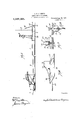
- Figure l is; a side elevation, partly in section, showing the device of my invention on a reduced scale
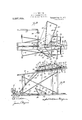
- Fig.2 is a View in side elevation on an I enlarged scale showing the transfer. device taking-a ball from .the supply device for delivery to the reserve device,
- Fig. 3 is a plan view-thereof with the parts in the position shown in F 1g; 2.
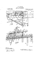
- Fig. 4- is an enlarged planview of a portion of the reserve feed device and showing the throwing device in a receiving position with respect to the reserve" feed device.
- FIG. 5 is a sectional view on line 5-5 of Fig. 4:
- Fig. 6 is a detached perspective view of a controlling slide'for controlling delivery of other-extremity.
- a platform 4 is incorporated in the structure and disposed adjacent the screen 2 and leading from the platform ate a delivery or supplytrough 5, is an inclinedrun way 6 which is in the form'of a fiooringonwhich the balls arrestedby the screen-2 rebound androll'backwardly into trough'5' by gravity.
- Trough 5 may be profeed boardvided with an'oppositely inclined 7, deliveringto the trough.
- a track 10 which is shown T-shaped in cross section.
- the track 10' is pivotally mounted on the table at 11; and I provide means for adjusting the track at the throw-' ing point so as to-vary the inclination of
- 8 designates asupporting table mounts ed upon suitable uprights 9 and supported the trackfor the purpose: of altering the tra jectory of the ball and also to vary its ele-' vation of delivery to the batter;
- a U-shaped bracket l2 is mounted to depend from the, table-Sand isbored tolooselyreceive a threaded rod .1'31for adjustment therethrough.
- the rod 13 projects through a suitable openingin the table 8 and is pivotally connected at'l5 with the track 10.
- a ball throwing device Slidably mounted on the track 10 for linear reciprocating movement thereon is a ball" throwing device comprising a trough like supportingportion 16 and a cupped backing 17, in which the ball is held and from which it is thrown.
- the supporting portion 16 terminates in bottom and laterally disposed marginally disposed fingers 18 and 19.
- The. throwing. device includes a carriage 20 which is slidable on track 10 and.which is provided with underhung-lips 21gand 22. to i hold the carriage upon track 10. Disposed rearwardlyrof the cup shaped back l7,is an upright 23 having marginally slottedportionsQt, i' t, w
- w-w' ,Oppositely ⁇ disposed pivot brackets 25 ex tend inopposite directions from their points of mount 26, 011 thetable 8, and terminates in pivot ends 27-.
- - Arms28 are mounted on the ends 27-by pivots129, at points between the ends of said arms and ll'lrSHCll a-inannerasto dispose. the shorter ends outwardly and the longer ends inwardly.
- the i inner or longer ends terminate 1nhooks-s30 provided with rings 81.v Endless straps 82 are coni nectedzwith: ringswS-lfand. with the slottedportions-24L; :Theouten ends. OfzSELld.
- Lever is pivoted at 4L6 to a suit able brace comprising brace rods 47 herein shown connected with the table 8, atlS.
- lever is connected at 49 wlth a llnk or rod 50.
- the remalnmg end of said link rod 50 is connected at 51 with a detent carriage 52 whichis slidabl'e upon track 10, independently of the ball device carriage 20.
- the latter is shown provided with a latch like detent lug 53 ove-r'which a detent 54 is adapted toproject, into the position shown in Fig. 5 forv connecting said carriages during, retractiverdovement;
- Detent 54 is pivoted at 55 to detent carriage" 52 and is provided witha rearwardly projecting releasing end 56. I S r Now when the ball carriage is in the positionishown in Fig.
- A, preferably fixed releaser57q is disposed inthe path of the releasingend 56,
- a receiver comprisinga bottom board'58 disposed on an incline above tabl.e'8 and mounted upon supports and 60. T'he' receiv is provided with incloslng sides-61,- 62; 63
- a sliding closure 66 is mounted in-supports 67 to be reciprocated abreast of thebottom of the receiver board 3 into the-position shown in Fig. 5, when-the ball carrying carriage 20 is being moved to-- ward a set position to be tripped and it will be seen that the sliding closure 66' will have beenretracted'into a ball delivery position prior torelease tr detent 54 from lug 53 for actuation of the ball carrying carriage 20. This insures deliveryby gravity of a ball into the carriage 20 prior to release of the latter.
- the sliding closure 66 is provided with-a ball arrester '74 which projects upwardly through a suitable slot 75, in bottom board 58, the highest point 76 serving to close passage 77 when the closure is inthe position shown in Fig. and the reduced or lower portion 78 serving to open said passage when the slide is in the position shown in F ig. 2.
- Rod mount will act as'a stop against the rear-most bearing strap 67 to limit forward movement of the slide. .It will be seen that the receiver is capable of holding a reserve number of balls so that as balls are fed therefrom others will automatically take the place of the displaced balls.
- a rock shaft is mounted in suitable bearings 80 and is provided with an arm 81 which is connected at 82 with a link 83, at one end of the latter.
- the other end of said link 83 is connected at 84 with a clip 85 which is adjustable on the operating rod 43 by means of a screw 86. This adjustment permits of readily setting the transfer device in the desired timed operative relation with rod 43.
- Rock shaft 79 is provided with a transfer arm 87 which is provided on its one end with a ball carrying cup 88.
- Trough 5 is provided with an opening 89 of sufiicient size to permit of passage therethrough of one ball at a time.
- Means such as a spring 90, normally acts'to prevent passage of the lowermost ball throu h said opening 89, the trough 5 being inclined for gravitation of the balls therein toward said opening 89.
- the transfer arm 87 then being moved from the dotted-line position to the full-line position of Fig. 2, when the cup 88 will engage the spring 90, allowing the latter to retract and ball to be discharged through the opening 89 into the cup 88.
- the presence of the ball n the cup however will hold the next ball against discharge from trough 5 until cup 88 has been elevated.
- a track bar means for adjusting said bar into different positions, anobject throwing carriage, a trip carriage mechanism slidable on said bar and having means for engagement with said throwing carriage to retract the latter, and automatically acting means for engagement with said trip carriage mechanism to release said throwing carriage means upon retraction of the latter to a predetermined point, substantially as described.
- trip-carriage mechanism slidable on said traclcbar, and having means for engagement with said object throwing carriage to retract the latter, and automatically actuating means for engagement with said trip-carriage mechanism to release said object throwing carriage means upon retraction of thelatter to a predetermined point.
- a track-bar a detent carriage slidable on said track-bar, a slide having an object-receiving opening, an object throwing carriage, mounted upon said track-bar, a retractor on said detent-carriage for moving said slide into a ball or object delivery position, said detent carriage having means for engagement with said objectthrowing carriage to retract the latter, and automatically actuating means for engagement with said trip-carriage mechanism to release said obj cot-throwing carriage means upon retraction of the latter to a predetermined point.
- a track-bar, an object-throwing carriage and a trip-carriage slidably mounted on the track-bar, a spring controlled slide having an object receiving opening, a depending member carried by said slide, an upwardly extended retractor carried by said trip-carriage adapted to engage said depending member, connecting and releasing elements carried by said trip-carriage and said object-throwing carriage, means for retracting said carriages, and means for actuating said releasing elements to release said objectthrowing carriage upon retraction thereof 6,
- ball hold throWingmeans comprising bendable fingers for engagement Wltll Varying pressures of oontact with'respectto different spherical portions of the ball to curve the latter, substantially as described.
- a ballsupply trough provided with an opening, a spring. normally preventing discharge of balls through said opening, a ball throwing means, a reserve receiver-for delivering balls to said throwing means, and transfer means for transferring the balls from said supply trough to said reserve receiver and co aeting with said spring to receive balls from said trough, substantially as described;
Landscapes
- Health & Medical Sciences (AREA)
- General Health & Medical Sciences (AREA)
- Physical Education & Sports Medicine (AREA)
- Branching, Merging, And Special Transfer Between Conveyors (AREA)
Description
A.-B. FERGUSON. OBJECT THROWING MACHINE.
- v APPLICATION FILED FEB. 25. 1915. 1,237,625. Patented Aug. 21, 1917.
a SHEETS-SHEET 1.
I I Wa A. B. FERGUSON.
OBJECT THROWING MACHINE.
APPLICATION FILED FEB. 25. 1915.
1 31,625, Patented Aug". 21, 1917.
I 3 SHEETSSHEET 2. W
A. B. FERGUS'ON. v v OBJECT THRQWING MACHINE. 1,237,625.
APPLICATION FILED FEB. 25'. I915.
; Unrrn, STATES m n ARCHIBALD BRUCE FERGUSON, CP -SPOKANE, WASHINGTON, ASSIGNO R lO ARROW MANUFACTURING COMPANY, OF WASI-IINGTO1\T..
To all whom it mar concern:
it-known that I, ARGHIBALD BRUCE Fnncusom, a citizen of the United States, residing at Spokane, inthecounty of Spokane and State of W'ashington, have invented certain new and useful Improvements in I Object-Throwing Machines, of which the following is a specification.
This invention relates to improvements in projectile throwing machines and has to do I more-particularlyg with machines of this class for use in connectionwith games such for instance as'basebalhthe device of my invention being used more particularly for practice batting purposes. 1
It isone of the .objects of-this invention to providea throwing device which is linearly movable from a ball taking toward and to a ball discharging position.
A further object of the invention is to provide areserve feed device for gravity delivery of one ball at a time to the throwing device, the reserve feed device holding a reserve quantity or number of balls whose discharge therefrom, one by one, is automatically controlled by movement of the throwing device.
A further object. of the invention is to provide a supply device with a transfer means for=automatically transferring baseballs or other game projectiles from the supply device to the reserve device, automatically, during operation of the throwing devlce. .i
A further object. of the invention is to provide a ball throwing device which. is capable of grasping the ballin such a, man.- ner. as to curve the same when it is thrown.
Further objects and featuresof the invention will be more fully described-in con nection with the accompanying drawings, and will be more particularly pointed out in and by the appended claims.
In the drawings Figure l is; a side elevation, partly in section, showing the device of my invention on a reduced scale,
Fig.2 is a View in side elevation on an I enlarged scale showing the transfer. device taking-a ball from .the supply device for delivery to the reserve device,
Fig. 3 is a plan view-thereof with the parts in the position shown in F 1g; 2.
SPOKANE, WASHINGTON, A. CORPORATIONOF oBJEoT-Tnnowme MACHINE. I
Specification of Iietters Patent. Patented Aflg', 21, 1917,
' Application filed. February 25, 1915. Serial No. 10,6467.
Fig. 4- is an enlarged planview of a portion of the reserve feed device and showing the throwing device in a receiving position with respect to the reserve" feed device. ,.Fig. 5 is a sectional view on line 5-5 of Fig. 4:, Fig. 6 is a detached perspective view of a controlling slide'for controlling delivery of other-extremity. A platform 4 is incorporated in the structure and disposed adjacent the screen 2 and leading from the platform ate a delivery or supplytrough 5, is an inclinedrun way 6 which is in the form'of a fiooringonwhich the balls arrestedby the screen-2 rebound androll'backwardly into trough'5' by gravity. Trough 5 may be profeed boardvided with an'oppositely inclined 7, deliveringto the trough.
ting platform 4.- Mounted upon the table. 8 is a track 10 which is shown T-shaped in cross section. The track 10' is pivotally mounted on the table at 11; and I provide means for adjusting the track at the throw-' ing point so as to-vary the inclination of Referring more particularly to Figs. 2 to 5, 8 designates asupporting table mounts ed upon suitable uprights 9 and supported the trackfor the purpose: of altering the tra jectory of the ball and also to vary its ele-' vation of delivery to the batter;
' Asshown, a U-shaped bracket l2;is mounted to depend from the, table-Sand isbored tolooselyreceive a threaded rod .1'31for adjustment therethrough. .-The rod 13 is not only adjusted butis heldin adjusted positions by nuts 14 which arethreaded on the rod=and which engage opposite faces of the bracket 12, as will be seen by reference to r Fig. 8. The rod 13 projects through a suitable openingin the table 8 and is pivotally connected at'l5 with the track 10.
Slidably mounted on the track 10 for linear reciprocating movement thereon is a ball" throwing device comprising a trough like supportingportion 16 and a cupped backing 17, in which the ball is held and from which it is thrown. The supporting portion 16 terminates in bottom and laterally disposed marginally disposed fingers 18 and 19. The
' r The. throwing. device includes a carriage 20 which is slidable on track 10 and.which is provided with underhung-lips 21gand 22. to i hold the carriage upon track 10. Disposed rearwardlyrof the cup shaped back l7,is an upright 23 having marginally slottedportionsQt, i' t, w
-The= improved actuating means for the throwing device is shown in theform'of the following specific construction. w-w' ,Oppositely{disposed pivot brackets 25 ex tend inopposite directions from their points of mount 26, 011 thetable 8, and terminates in pivot ends 27-.- Arms28 are mounted on the ends 27-by pivots129, at points between the ends of said arms and ll'lrSHCll a-inannerasto dispose. the shorter ends outwardly and the longer ends inwardly. The i inner or longer ends terminate 1nhooks-s30 provided with rings 81.v Endless straps 82 are coni nectedzwith: ringswS-lfand. with the slottedportions-24L; :Theouten ends. OfzSELld. arms 28 terminate in eyes 33=to which the ends 34 of springs 35, are-connected. :zThe remaining ends 36, of said springs, are connected-with adjusting rods '37 having threaded connection: with-sbrackets*38.x If desired, the springs 35 may be covered by rubber hose or like. flexible tubular omaterial as I indicted Now it will be clear that when the carriage =20 is retracted-st the positionshown in-Fig's. 4: and: 5, the springs 35 will be under tension, and afterthe carriage has been re leased, the springs 35 will project the latter into the positionshown in Figs. 3 and 4, to throw the ball.
I will next describe the'means for setting or retracting'the carriage into a ball receiv ing position and-;thereafter releasing -the carriage "for: actuation by'sp'rmgs' 35.
An 'ope'ratrnglever- 40 1s plvotally mounted at 4:1 and-is connected at 42 with a shifting-rod 43. 'Theremaining end of said rod 43 is connected at 44 with one end of a lever 4-5. Lever is pivoted at 4L6 to a suit able brace comprising brace rods 47 herein shown connected with the table 8, atlS. The
remaining end of lever is connected at 49 wlth a llnk or rod 50. The remalnmg end of said link rod 50 is connected at 51 with a detent carriage 52 whichis slidabl'e upon track 10, independently of the ball device carriage 20. The latter is shown provided with a latch like detent lug 53 ove-r'which a detent 54 is adapted toproject, into the position shown in Fig. 5 forv connecting said carriages during, retractiverdovement; Detent 54 is pivoted at 55 to detent carriage" 52 and is provided witha rearwardly projecting releasing end 56. I S r Now when the ball carriage is in the positionishown in Fig. '3, and it'is desired to retract said carriage to aset position, lever 40 is shifted to the left of'Fig. 1 to engage detent=5 with lug and then lever 40 is shifted to the right of Fig. 1 to retract carriage 20: A, preferably fixed releaser57q is disposed inthe path of the releasingend 56,
for engagement thereby, to release-the detent fromwcn'ga'gement with lug 53 after the 'carriage has been retractedto a predetermined point, such release freeing the carriage 20 for forward movement under the action of springs 35.11 1' v 1 q I will next describe thereserve feed device for gravity delivery to theball throwing device of the base' ball er -other objects tobethrown. 1 x
,In the specific form, I have shown a receiver comprisinga bottom board'58 disposed on an incline above tabl.e'8 and mounted upon supports and 60. T'he' receiv is provided with incloslng sides-61,- 62; 63
and 64, and near one end'o'f the receiver-is an; opening :65 fol delivery. therethrough of the baseballs. A sliding closure 66 is mounted in-supports 67 to be reciprocated abreast of thebottom of the receiver board 3 into the-position shown in Fig. 5, when-the ball carrying carriage 20 is being moved to-- ward a set position to be tripped and it will be seen that the sliding closure 66' will have beenretracted'into a ball delivery position prior torelease tr detent 54 from lug 53 for actuation of the ball carrying carriage 20. This insures deliveryby gravity of a ball into the carriage 20 prior to release of the latter. The inclination of the reserve receiver is downwardlyfrom 61 to 64 so that the ball therein will gravitate toward opening 65. In order to prevent more than one ball from entering said opening,at a 'time, the sliding closure 66 is provided with-a ball arrester '74 which projects upwardly through a suitable slot 75, in bottom board 58, the highest point 76 serving to close passage 77 when the closure is inthe position shown in Fig. and the reduced or lower portion 78 serving to open said passage when the slide is in the position shown in F ig. 2. Rod mount will act as'a stop against the rear-most bearing strap 67 to limit forward movement of the slide. .It will be seen that the receiver is capable of holding a reserve number of balls so that as balls are fed therefrom others will automatically take the place of the displaced balls.
I will next describe the transferring means for transferring balls from the supply device or trough 5 to the reserve receiver.
A rock shaft is mounted in suitable bearings 80 and is provided with an arm 81 which is connected at 82 with a link 83, at one end of the latter. The other end of said link 83 is connected at 84 with a clip 85 which is adjustable on the operating rod 43 by means of a screw 86. This adjustment permits of readily setting the transfer device in the desired timed operative relation with rod 43. Rock shaft 79 is provided with a transfer arm 87 which is provided on its one end with a ball carrying cup 88. Trough 5 is provided with an opening 89 of sufiicient size to permit of passage therethrough of one ball at a time. Means such as a spring 90, normally acts'to prevent passage of the lowermost ball throu h said opening 89, the trough 5 being inclined for gravitation of the balls therein toward said opening 89. Now when the rod 43 is moved to the left the carriage 52 is moved in the same direction to engage the ball carriage 20, the transfer arm 87 then being moved from the dotted-line position to the full-line position of Fig. 2, when the cup 88 will engage the spring 90, allowing the latter to retract and ball to be discharged through the opening 89 into the cup 88. The presence of the ball n the cup however will hold the next ball against discharge from trough 5 until cup 88 has been elevated. Immediately upon elevation of cup 88, spring 90 will follow and return to a normal position and prevent the next ball from dropping out through opening 89. When the detent carriage is moved into the position shown in Fig. 5, the transfer arm 88 will be moved into the delivery position shown in this figure and will deliver its balls to the receiver for reserved balls. Thus as each ball is discharged from the reserve receiver, the supplywill be replenished by the transfer mechanism. Furthermore, as each thrown ball strikes the screen'2, it will rebound and roll down the run way 6, by gravity, into supply trough 5.
It is believed that the device of my invention will be wholly understood from the foregoing description and while I have herein shown and described one specific'form of my invention, I do not wish to be limited thereto except for such limitations as the claims may import.
1. In an object throwing mechanism, a track bar, means for adjusting said bar into different positions, anobject throwing carriage, a trip carriage mechanism slidable on said bar and having means for engagement with said throwing carriage to retract the latter, and automatically acting means for engagement with said trip carriage mechanism to release said throwing carriage means upon retraction of the latter to a predetermined point, substantially as described.
2. In an object throwing mechanism a track-bar, an object-throwing carriage, a.
(trip-carriage mechanism slidable on said traclcbar, and having means for engagement with said object throwing carriage to retract the latter, and automatically actuating means for engagement with said trip-carriage mechanism to release said object throwing carriage means upon retraction of thelatter to a predetermined point.
8. In an object throwing mechanism, a track-bar, a detent carriage slidable on said track-bar, a slide having an object-receiving opening, an object throwing carriage, mounted upon said track-bar, a retractor on said detent-carriage for moving said slide into a ball or object delivery position, said detent carriage having means for engagement with said objectthrowing carriage to retract the latter, and automatically actuating means for engagement with said trip-carriage mechanism to release said obj cot-throwing carriage means upon retraction of the latter to a predetermined point. I
4. In an object throwing mechanism, a track-bar, an object-throwing carriage and a trip-carriage slidably mounted on the track-bar, a spring controlled slide having an object receiving opening, a depending member carried by said slide, an upwardly extended retractor carried by said trip-carriage adapted to engage said depending member, connecting and releasing elements carried by said trip-carriage and said object-throwing carriage, means for retracting said carriages, and means for actuating said releasing elements to release said objectthrowing carriage upon retraction thereof 6, In a ball thlrowing machine, ball hold throWingmeans comprising bendable fingers for engagement Wltll Varying pressures of oontact with'respectto different spherical portions of the ball to curve the latter, substantially as described.
In testimony whereof I aflixiny signature in presence of two witnesses.
AROHIBALD BRUCE FERGUSON.
v Witnesses E J. J Y. LAVIN,
STELLA LOMBARD.
Copies of thisipaten't may he obtained for fi vei cents each, by addressing" the Commissioner of Patents,
, Washington, D. C.
Priority Applications (1)
| Application Number | Priority Date | Filing Date | Title |
|---|---|---|---|
| US1064715A US1237625A (en) | 1915-02-25 | 1915-02-25 | Object-throwing machine. |
Applications Claiming Priority (1)
| Application Number | Priority Date | Filing Date | Title |
|---|---|---|---|
| US1064715A US1237625A (en) | 1915-02-25 | 1915-02-25 | Object-throwing machine. |
Publications (1)
| Publication Number | Publication Date |
|---|---|
| US1237625A true US1237625A (en) | 1917-08-21 |
Family
ID=3305444
Family Applications (1)
| Application Number | Title | Priority Date | Filing Date |
|---|---|---|---|
| US1064715A Expired - Lifetime US1237625A (en) | 1915-02-25 | 1915-02-25 | Object-throwing machine. |
Country Status (1)
| Country | Link |
|---|---|
| US (1) | US1237625A (en) |
Cited By (3)
| Publication number | Priority date | Publication date | Assignee | Title |
|---|---|---|---|---|
| US2755788A (en) * | 1953-12-17 | 1956-07-24 | John S Edwards | Catapult |
| US5123643A (en) * | 1991-07-25 | 1992-06-23 | Perfect Pitch, Inc. | Ball throwing apparatus |
| US5431145A (en) * | 1993-09-09 | 1995-07-11 | Strait; Renus D. | Method and apparatus for pitching an object |
-
1915
- 1915-02-25 US US1064715A patent/US1237625A/en not_active Expired - Lifetime
Cited By (3)
| Publication number | Priority date | Publication date | Assignee | Title |
|---|---|---|---|---|
| US2755788A (en) * | 1953-12-17 | 1956-07-24 | John S Edwards | Catapult |
| US5123643A (en) * | 1991-07-25 | 1992-06-23 | Perfect Pitch, Inc. | Ball throwing apparatus |
| US5431145A (en) * | 1993-09-09 | 1995-07-11 | Strait; Renus D. | Method and apparatus for pitching an object |
Similar Documents
| Publication | Publication Date | Title |
|---|---|---|
| US4995371A (en) | Ball throwing machine | |
| FI96180C (en) | Training device for kicking balls, especially footballs | |
| US3277878A (en) | Baseball throwing machine | |
| US1237625A (en) | Object-throwing machine. | |
| HU194059B (en) | Ball-serving device | |
| US1552191A (en) | Target-throwing apparatus | |
| US1897317A (en) | Ball throwing apparatus | |
| US6631828B1 (en) | Golf ball and tee placement unit | |
| US930918A (en) | Toy. | |
| US1339846A (en) | Ball game | |
| US540318A (en) | Target-trap | |
| US702415A (en) | Mechanical base-ball pitcher. | |
| US479820A (en) | little | |
| US3262439A (en) | Ball throwing machine | |
| US1086067A (en) | Base-ball apparatus. | |
| US629044A (en) | Catapult for throwing projectiles. | |
| US554990A (en) | Target-throwing trap | |
| JPH09122286A (en) | Table tennis ball shooting apparatus | |
| US945395A (en) | Mail-bag catching and delivering apparatus. | |
| US403096A (en) | Spring-gun | |
| US1091992A (en) | Projecting device. | |
| JP6777932B2 (en) | Ball supply device using air pressure | |
| US670629A (en) | Rapid-fire toy cannon. | |
| US1242942A (en) | Game apparatus. | |
| US912996A (en) | Mail-handling apparatus. |