US123761A - Improvement in elevators - Google Patents
Improvement in elevators Download PDFInfo
- Publication number
- US123761A US123761A US123761DA US123761A US 123761 A US123761 A US 123761A US 123761D A US123761D A US 123761DA US 123761 A US123761 A US 123761A
- Authority
- US
- United States
- Prior art keywords
- carriage
- platform
- lever
- elevator
- ofthe
- Prior art date
- Legal status (The legal status is an assumption and is not a legal conclusion. Google has not performed a legal analysis and makes no representation as to the accuracy of the status listed.)
- Expired - Lifetime
Links
- 230000000694 effects Effects 0.000 description 6
- 210000003414 extremity Anatomy 0.000 description 5
- 239000003795 chemical substances by application Substances 0.000 description 3
- 238000010276 construction Methods 0.000 description 3
- 239000000463 material Substances 0.000 description 3
- VAYOSLLFUXYJDT-RDTXWAMCSA-N Lysergic acid diethylamide Chemical class C1=CC(C=2[C@H](N(C)C[C@@H](C=2)C(=O)N(CC)CC)C2)=C3C2=CNC3=C1 VAYOSLLFUXYJDT-RDTXWAMCSA-N 0.000 description 2
- 238000005760 Tripper reaction Methods 0.000 description 2
- 230000000994 depressogenic effect Effects 0.000 description 2
- 210000003141 lower extremity Anatomy 0.000 description 2
- 239000011435 rock Substances 0.000 description 2
- 102100027256 Melanoma-associated antigen H1 Human genes 0.000 description 1
- 230000001174 ascending effect Effects 0.000 description 1
- 239000004020 conductor Substances 0.000 description 1
- 108010038764 cytoplasmic linker protein 170 Proteins 0.000 description 1
- 230000000881 depressing effect Effects 0.000 description 1
- 230000003028 elevating effect Effects 0.000 description 1
- 239000004744 fabric Substances 0.000 description 1
- 229920000136 polysorbate Polymers 0.000 description 1
- 230000000630 rising effect Effects 0.000 description 1
- 210000001364 upper extremity Anatomy 0.000 description 1
- XLYOFNOQVPJJNP-UHFFFAOYSA-N water Substances O XLYOFNOQVPJJNP-UHFFFAOYSA-N 0.000 description 1
Images

Classifications
-
- B—PERFORMING OPERATIONS; TRANSPORTING
- B66—HOISTING; LIFTING; HAULING
- B66B—ELEVATORS; ESCALATORS OR MOVING WALKWAYS
- B66B5/00—Applications of checking, fault-correcting, or safety devices in elevators
- B66B5/02—Applications of checking, fault-correcting, or safety devices in elevators responsive to abnormal operating conditions
- B66B5/16—Braking or catch devices operating between cars, cages, or skips and fixed guide elements or surfaces in hoistway or well
- B66B5/18—Braking or catch devices operating between cars, cages, or skips and fixed guide elements or surfaces in hoistway or well and applying frictional retarding forces
Definitions
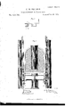
- FIG. 1 is a front elevation; Fig. 2, a side elevation; Fig. 3, a vertical central and longitudinal section; and Fig. 4, a rear elevation of an elevator in which my improvements are embodied.
- Fig. 5 is an elevation of one of the recessed brackets, or housings, and its ac.
- My present invention consists, first, in suspending and operating an elevator-carriage from the bottom thereof, in lieu of the top as now universally practiced, my purpose in so doing being threefold; first, to reduce very greatly the present weight of an elevator-carriage, and by this means lessen the cost -would precipitatethe former to the bottom of the building.
- these improvements embrace an automatic brake or stop mechanism, whereby, up'on failure of the attendant through inattention or preoccupation to apply his handebrake and stop the motion of the carriage as the top or bottom of the building (or, when desirable, a landing) is reached, the said brake is forced to act without the aid of the attendant;
- this portion of the invention consisting in the employment of a vibratory bar swiveled to a hanger depending from the front of the platform, and provided with an antifriction roller upon its forward and free end, the said vibratory bar being i'ulcrumed at .about its center to the lower end of a shipping or reversing lever'or cast-off, the handle whereof rises into the interior of the carriage or above the platform, a ledge or shelf being formed upon such shipping-lever upon which rests the outer end of a secondvibratory le,-
- the accompanying drawing represents at A a horizontal platform of suitable proportions and construction to constitute the bottom or tloorin g of an elevator-carriage or car, the superstructure B of the car being, in this case, a very light one, and composed of lattice-work or other reticulated or ornamental material, the top thereof being, bypreterence, composed of cloth or other material which shall be an ineffectual conductor of sound, in order that conversation or other sounds or noises within the car may not disturb the various occupants of. a building.
- an upright beam or bar, F or F' which is disposed within the roller recesses E of the housings and immediately againstthe rear wall thereof, and extending from basement to attic of the structure, these bars or slides being' stayed or supported each by an upright column, G or G', which is placed outside and alongside thereof, as represented, these columns serving in addition to support the drums H or H', about the peripheries of which pass the suspensories I I' of the platform A, these drums being situated at the extreme upper part of the structure containing the elevator.
- the suspensories I I' are connected at their rear extremities ,c a, Ste., or
- the drums or pulleys H H' are disposed obliquely to each other and to the sides of the platform A or carriage B, this triangulate enabling me to employ large drums and apply the suspensories of both directly to a bucket of comparatively small diameter.
- releasing-rods L L or L' L', (see Fig. 4 of the drawing) equal in aggregate number and coincident in position with the suspensoriesL L', and depressed by plate springs c c, Ste., suitably applied, and I connect to the upper end of-each rod or bolt the end b of the next adjacent suspensory, the opposite ends c a, tc., of such suspensories being connected, as before stated, to the bucket J. I thus carry out the iirst portion ot' these improvements, and
- each tripper extends into and nearly spans the .lower part of the recess or channel E, and so as to intercept and support at certain times a iiuted, roughened, or other roller, P, which is depos ited in such recess, the diameter of this roller being less than the greatest width of the recess and greater than the smallest width thereof, the shaft O serving to connect thetrippers upon opposite sides of the platform and compel them to act in unison.
- 'Q in the drawing represents a curved vibratory or swinging bar, swiveled at its inner end, as shown at e, to the lower part of a han ger, R, depending from the front part of the cheek U, the lower extremity of the said bar carrying an anti-friction roll, S, which is mounted upon a horizontal stud, T, projecting outwardly and laterally from the bar, as represented in Fig. l of the drawing.
- a pitman, X has its lower end pivoted, Aas shown at j, to the arm 1', and thence rises above the platform A, where it is pivoted to a hori' zontal rod, Y, this rod in turn being fu'lcrunied at rear to a post, Z, erected upon the said platform A, the forward extremity of the rod Y terminating in a handle, 7c, which is atsuch a height as to be readily grasped by the attendant of the carriage.
- the brake mechanism herein shown is repeated in duplicate upon opposite sides ofthe elevator, therefore the explanation of one side will suffice; and it consists of two rectangular twin-shaped and dually-arranged blocks, l l', embracing opposite sides ofthe slide F or F', and pivoted at each end to one of two oscillating bars, m or m', the uppermost one (m) of which is affixed to the extremity of the shaft V as a center, and the lowermost (m') fulcrumed to a pin or stud, n, extending laterally from the lower extremity of the cheek G or a hanger, C2, making part thereof.
- the space intervening between the two blocks Z l' when the supports or bars m m' are horizontal is 1 somewhat greater than the thickness of the slides F, and the depression of the hand-lever or rod Y has the effect of forcing these blocks to such a position as to clamp the slide, a suitable stop being combined with the apparatus to prevent the bars m m from bein g forced beyond a given point.
- the pressure upon the hand-lever Y leaves the spring VV free to act, which it does by partially rotating the shaft in the direction of its arrow, which forces the.
- roller S ofthe bar Q reaches a sloping deflect-or orinclined plane, A2, which is aiiixed to the column G and in vertical alignment with the roller or its path, this deiiector being situated at the extreme top and bottom of the building, or near one of the landings or stopping places of the elevator'.
- A2 sloping deflect-or orinclined plane
- This third part of my invention or automaticstop motion is not intended to include, as a necessary part thereof, a brake mechanism of any given kind, since various brakes may be employed in connection with such automatic device. N or do I herein limit myself to the details of mechanism constituting the automatic device herein shown, as Ibelieve myself entitled to any mechanical elements which shall effect a like result, in this instance.
- the roller P After fracture of a suspensory, the roller P remains wedged fast between the wall of the recess E andthe slide F, and requires considerable power to dislodge it; but as a suspensory, if of good material, seldom or never breaks, this liability is of little consequence, as the cylinder or stand-pipe K below the equipoising bucket may contain a greater or less amount of air, or an entire or partial vacuum may exist therein. I propose, if circumstances render desirable, to employ this entire or partial vacuity as a means of arresting the motion of the elevator-carriage should a suspensory break, or should the attendant fail, as hereinbefore stated, to stop such motion on reaching the top or bottom ofthe building.
- valve whereby a greater or less amount of air may be admitted to its interior, and this valve may be operated by a mechanism which shall vbe controlled bythe attendant, or by an automatic stop-motion; or the valve may be actuated by a suitable agent placed at the top and bottom of the building, by which the air may be partially or entirely shut out of the stand-pipe and thus stop the motion of the carriage should the attendant fail to do so.
Landscapes
- Engineering & Computer Science (AREA)
- Mechanical Engineering (AREA)
- Braking Arrangements (AREA)
Description
4 Sheets--Sheet 1. C. W. BALDWIN.
improvement i'n Eevators. No. 123,761. Patented Feb.`2o,1872.
4 Sheets--Sheet 2.
C W B A L D W l N Improvement in Elevators. f
Patented Feb. 20, 1872.
ole v elwlwwlevl.
OOO 20202020202 4 Sheets--Sheet 4.
C. W. BALDWIN.
Improvement n Elevators.
Patented Feb.20, 1872.
UNITED Sra'rns PATENT FFICE.
CYRUS W. BALDWIN, OF BOSTON, MASSACHUSETTS, ASSlGNOR TO CHARLES VVHITTIER AND HENRY H. MCBURNEY, OF SAME PLACE.
IMPROVEMENT IN ELEvAToRs.
To all to whom these presents shall come:v
v Be it known that 1,0YRU-s W. BALDWIN, of
`Boston, in the county of Suffolk and Com-y monwealth of Massachusetts, have made an invention of certain new and useful Improve# ments in Elevators; and do hereby declare the following to be a full, clear, and exact description thereof, due reference being had to the accompanying drawing makin gpart of this specification, and in which- Figure 1 is a front elevation; Fig. 2, a side elevation; Fig. 3, a vertical central and longitudinal section; and Fig. 4, a rear elevation of an elevator in which my improvements are embodied. Fig. 5 is an elevation of one of the recessed brackets, or housings, and its ac.
cessories to be hereinafter explained.
(l.) First. My present invention consists, first, in suspending and operating an elevator-carriage from the bottom thereof, in lieu of the top as now universally practiced, my purpose in so doing being threefold; first, to reduce very greatly the present weight of an elevator-carriage, and by this means lessen the cost -would precipitatethe former to the bottom of the building. d
(2.) Second. And, secondly, my present improvements will be found to consist in anoveh mode of attaching the hoisting-ropes 01 suspensories to the carriage-floor or platform, and the combination therewith of a safety stopmotion or device, which, upon fracture of any one suspensory, sets free the said stop-motion and allows it to arrest the descent of the carriage and prevent accident; this secondportion of these improvements consisting in connecting the suspensories to the upper ends of a series ot' upright rods, playing in suitable brackets or housings, applied to one or both sides of the platform and providedwith springs to depress them under certain conditions, the lower ends of said rods restin gupon the inner extremity of a tilting or oscillating lever fulcrumed to the side'ot' the platform and below the brackets or housings above named, the outer or front extremity of the said lever being situated below the inner and free end of an arm or tripper afxed to one end of a horizontal rock-shaft, which rocks in suitable bearin gs placed below the carriage-platform, the last element in this safety device being a iiuted roller, which, in turn, rests upon the free end of the tripper above named and is deposited in a converging channel, contracted at the top, said channel being a groove or recess created in the housing or bracket above named and in which an upright rail or slide is situated, the arrangement of parts being such that upon fracture of one suspensory, the rod to which it is attached is suddenly lowered by the action of its spring, the descent of the rod, through the agency of the oscillating lever and tripper above named, having the effect of throwing the Huted roller with a quick movement upward into the contracted portion of its channel and between the front wall of the latter and the bar "or slide above referred to, the' roller being so firmly wedged between the two a-s to lock 'them together, and consequently arrest instantly the descent of the carriage.
(3.) Third. And, thirdly, these improvements embrace an automatic brake or stop mechanism, whereby, up'on failure of the attendant through inattention or preoccupation to apply his handebrake and stop the motion of the carriage as the top or bottom of the building (or, when desirable, a landing) is reached, the said brake is forced to act without the aid of the attendant; this portion of the invention consisting in the employment of a vibratory bar swiveled to a hanger depending from the front of the platform, and provided with an antifriction roller upon its forward and free end, the said vibratory bar being i'ulcrumed at .about its center to the lower end of a shipping or reversing lever'or cast-off, the handle whereof rises into the interior of the carriage or above the platform, a ledge or shelf being formed upon such shipping-lever upon which rests the outer end of a secondvibratory le,-
ver, the rear end of which, in turn, is affixed rigidly to the rock-shaft, upon which is mounted the brake mechanism which grasps the upright slides hereinbefore named, the said le ver having pivoted to it a pitman which rises above thc platform and is connected to a horizontal handle suitably supported, the depression of thelast-named lever, by means of such handle, havin g the effect ofreleasing the brake, and vice versa, the arrangement of parts in this instance being such that when the top or bottom of the building, (or, if desirable, a landing) is reached, the roller of the vibratory bar before named impinges against a sloping fender or detlector placed in the path of movement of such bar, by which the latter is elevated and with it the vibratory lever which has been above referred to as attached rigidly to the brake-shaft, the elevation of this lastnamed lever bringing the brake' into action and stopping the motion of the carriage.
v rIhis automatic stop mechanism is so applied,
and its reversing lever so adapted to it and to the brake mechanism, that said stop mechanism may be used or not at pleasure according' to the position in which the lever is suffered to remain. n
' (4.) Fourth. And,fourthly, I have incorporated in these improvements a chain or series of weights whereby the equipoise of the suspenseries of the carriage is elfected at all points in its path of movement, the preponderance of the weight of the increasing length of suspensories uponone side of the supporting drum, as the carriage ascends, being equipoised by theequally increasing Weight of the chain or weights upon the opposite side of such drum, and which are picked up or brought into requisition one after another,` and vice versa, as the carriage descends, the weight of the carriage per se being counter-balanced in any one of several modes now adopted, according to the class of elevators which is to be supplied with my improvements.
I have adopted, in explaining these improvements, a class of elevators shown and described in Letters Patent ofthe United States numbered 99,0-19, and issued to me on the 25th day of January, 1870, for HydraAtmospheric Elevator, in which the carriage is balanced by a bucket, to which water is supplied or removed in varying quantities according to the weight ofthe carriage and the direction in which it is to travel.
The accompanying drawing represents at A a horizontal platform of suitable proportions and construction to constitute the bottom or tloorin g of an elevator-carriage or car, the superstructure B of the car being, in this case, a very light one, and composed of lattice-work or other reticulated or ornamental material, the top thereof being, bypreterence, composed of cloth or other material which shall be an ineffectual conductor of sound, in order that conversation or other sounds or noises within the car may not disturb the various occupants of. a building.
Upon each side of the platform A and depending below it, I affix a thin side plate or cheek, C or G', while outstanding upon these plates, and centrally thereof and ofthe platform, I affix to each a recessed or channeled bracket or housing, D or D', of which a side elevation is shown in Fig. 2, aswell as several details connected therewith, the contour of the upright channel or recess E of such housing being as shown-that is to say, with its rear wall a vertical plane and its front wall an inclined or sloping pla-ne, the'two converging` at top. Furthermore, upon each side of the platform A I erect, upon the lo`wer door of the structure in which the elevator is placed, or uponl the foundation of the elevator whatever it may be, an upright beam or bar, F or F', these bars being disposed within the roller recesses E of the housings and immediately againstthe rear wall thereof, and extending from basement to attic of the structure, these bars or slides being' stayed or supported each by an upright column, G or G', which is placed outside and alongside thereof, as represented, these columns serving in addition to support the drums H or H', about the peripheries of which pass the suspensories I I' of the platform A, these drums being situated at the extreme upper part of the structure containing the elevator. The suspensories I I' are connected at their rear extremities ,c a, Ste., or
that portion in rear of the drums H H', to a" balancing or equipoisin g bucket, J, contained within and traversing a well or stand-pipe K; the nature of the well and bucket and their action upon the platform or carriage, being as described in my Letters Pat-ent number 99,QL9, before named, and requiring, in this connection, no extended notice.
The drums or pulleys H H' are disposed obliquely to each other and to the sides of the platform A or carriage B, this triangulate enabling me to employ large drums and apply the suspensories of both directly to a bucket of comparatively small diameter.
(l.) First, this above-described elementary construction of an elevator is such as has been or may be used (with the exception, perhaps, of the triangular arrangement of the carriage and drums) without direct connection with my present improvements, in carrying out which, in regular succession as hereinbefore premised, I proceed as follows: and first, to suspend and operate an elevator carriage. or platform from the bottom thereof, I dispose, within vertical .bearin gs formed in each housing D or D', one
or more releasing-rods, L L or L' L', (see Fig. 4 of the drawing) equal in aggregate number and coincident in position with the suspensoriesL L', and depressed by plate springs c c, Ste., suitably applied, and I connect to the upper end of-each rod or bolt the end b of the next adjacent suspensory, the opposite ends c a, tc., of such suspensories being connected, as before stated, to the bucket J. I thus carry out the iirst portion ot' these improvements, and
obtain, in so doing, results and advantages hereinbefore enumerated.
Y series of rods L, and being of sufficient width to overlap the lower ends or heads of each, while the forward extremity of suchlever abuts against the under side of a swinging armor tripper, Nor N', axed to the end of a horizontal rock-shaft, O, which is mountedin suitable bearings in the front part 'of the cheeks C C'. The inner and free end d' of each tripper extends into and nearly spans the .lower part of the recess or channel E, and so as to intercept and support at certain times a iiuted, roughened, or other roller, P, which is depos ited in such recess, the diameter of this roller being less than the greatest width of the recess and greater than the smallest width thereof, the shaft O serving to connect thetrippers upon opposite sides of the platform and compel them to act in unison.
This second portion of my invention last described' is the safety apparatus, as it is now generally termed, and its operation is as follows: Upon fracture of any one of the suspensories' I or I' its connection with the corresponding rod L or L' is severed, and the latter is driven by its spring c forcibly and instantaneously in contact with the rear end of the lever M or M', which effects a like sudden elevation of the free end of the tripper N or N', the'elevation of the tripper throwing the uted roller P upward into the throat of the recess E in such manner that it is wedged fast be-l tween the front boundary of the recess and the` adjoining face of the adjacent slide or bar F or F', and locks the latter to the housing, by this means instantly arresting the descent of the. latter, the weight of which aids in retaining the roller in place. As the two trippers are rigidly united by the shaft O a 'fracture of one suspensory sets free the safety apparatus upon both sides of the platform. By means of this second portion of my invention instant and unavoidable notice is given to the occupant of the car when one suspensory fails or parts, and enables the proper remedy to be availed of.
As it is morally certain that no two suspensorics would fail at the same time, this feature in my present improvements becomes anabsolute Ameans of safety against accidentalfall of an elevator-carriage, as the connections ofthe suspensories are not weakened by time and service, and nothing exists in the construction of the car above its platform to give way.
` I do not herein claim broadly the arrangemen-toi the safety device," as above explained, asl have shownV and laid claim to this in a former patent, the novelty in this connection consisting in asystem of so attaching the suspens'ories to this safety device that fracture of any one suspensory shall set the device free to act.
(3.) Third, in carrying out the third feature of these improvements, as enumerated in order in this context-that is, to insure the stoppage ofthe platform or carriage at the proper place should theattendant fail to do so-I combine with the hand-brake of the said platform a suitable mechanism which shall operate automatically to effect this object, and to carry out this end in one mode by which it may be simply and effectually accomplished, I proceed as follows, this device being applied in the present to the left side of the platform, although it maybe placed at either side, as may. be preferred.
'Q in the drawing represents a curved vibratory or swinging bar, swiveled at its inner end, as shown at e, to the lower part of a han ger, R, depending from the front part of the cheek U, the lower extremity of the said bar carrying an anti-friction roll, S, which is mounted upon a horizontal stud, T, projecting outwardly and laterally from the bar, as represented in Fig. l of the drawing. To the center or thereabout of the bar Q I-pivot the lower end of a cast-off" or'. hand lever, U, such lever rising upward through a slot in the ldoor or platform A. Toward the lower end or pivot f of the hand-lever U I form, upon such lever, an outwardly-projecti ng offset or shelf, y, while immediately over this shelf' I dispose the free end h of a horizontal vibratory arm or lever, i, the rear or inner end of this latter lever being affixed rigidly to a rock-shaft, V, which spans the area between the cheeks C C' and rocks in suitable bearings therein, this rockshaft being inclined to rotate in the direction of its arrow by the action of a volute spring, W, which is coiled about it and secured as shown in Fig. 4 of the accompanying drawing.
A pitman, X, has its lower end pivoted, Aas shown at j, to the arm 1', and thence rises above the platform A, where it is pivoted to a hori' zontal rod, Y, this rod in turn being fu'lcrunied at rear to a post, Z, erected upon the said platform A, the forward extremity of the rod Y terminating in a handle, 7c, which is atsuch a height as to be readily grasped by the attendant of the carriage. i v
The brake mechanism herein shown is repeated in duplicate upon opposite sides ofthe elevator, therefore the explanation of one side will suffice; and it consists of two rectangular twin-shaped and dually-arranged blocks, l l', embracing opposite sides ofthe slide F or F', and pivoted at each end to one of two oscillating bars, m or m', the uppermost one (m) of which is affixed to the extremity of the shaft V as a center, and the lowermost (m') fulcrumed to a pin or stud, n, extending laterally from the lower extremity of the cheek G or a hanger, C2, making part thereof. The space intervening between the two blocks Z l' when the supports or bars m m' are horizontal is 1 somewhat greater than the thickness of the slides F, and the depression of the hand-lever or rod Y has the effect of forcing these blocks to such a position as to clamp the slide, a suitable stop being combined with the apparatus to prevent the bars m m from bein g forced beyond a given point. The pressure upon the hand-lever Y leaves the spring VV free to act, which it does by partially rotating the shaft in the direction of its arrow, which forces the. arms m m into a sloping position, and compels aconvergence of the clamps or blocks L l', which, by the action of the sp1-ing, clamp the Vslide so firmly as to retain the carat any given altitude while a load is being added or removed, it being presupposed that the attendant, coincident with the act of lowering the handle 7c and releasing the brake, also sets in action the agent which raises or lowers the platform.
rlhe operation of the automatic-stop mechanism above-described, and which coustitutes,primarily, thus the third portion of these improvements, is as follows: .The depression of the handle 7c by the attendant, in the act of starting the carriage, depresses simultaneously the outer and free end ofthe arm t', and, consequently, partially rotates the shaft'V until the brake loses its hold upon the slides, at which time the end of the arm i has reached and abuts against the shelfl g ofthe han d-lever U, and the platform or carriage begins its journey, either ascending or descending. rlhe carriage continues to travel until the roller S ofthe bar Q reaches a sloping deflect-or orinclined plane, A2, which is aiiixed to the column G and in vertical alignment with the roller or its path, this deiiector being situated at the extreme top and bottom of the building, or near one of the landings or stopping places of the elevator'. Should the attendant, as the carriage reaches a landing or the end of its journey, and the roller S arrives in contact with the deiector A2, neglect to lessen or remove the lpressure exerted by him upon the handle 7c, the bar Q will be partially rotated by impact with the delector, and,by elevating the hand-lever U, also elevate the free end of the lever z', and permit the shaft V to be partially rotated by the action of the spring WV, which compels the brake to seize hold of the slide G and estop the movement of the carriage, as before stated.
The position in which the carriage and its adjuncts stop when arrested by then action of the bar Q and its accessories leaves the said barv and the hand-lever or cast-off77 U in such a situation that the arm which releases the hold of the brake upon the slide, cannot be depressed', owing to the presence of the shelf' g ofthe said hand-lever, which is immediately below the free end of said arm t'. Therefore,
be made for throwing the automatic-stop arrangement entirely out of action.
This third part of my invention or automaticstop motion is not intended to include, as a necessary part thereof, a brake mechanism of any given kind, since various brakes may be employed in connection with such automatic device. N or do I herein limit myself to the details of mechanism constituting the automatic device herein shown, as Ibelieve myself entitled to any mechanical elements which shall effect a like result, in this instance.
(4.) Fourth. Fourthly, and briefly, I carry out the remaining' division of these improvements by attaching to the under side of the platform A a chain, D2, the weight of which is such as to counterbalance the weight of that y portion ofthe aggregate suspensories which is disposed upon the side ofthe drums opposite the platform or its carriage or car. As this lastnamed portion of the suspensories increases in length and weight with the ascent of the platforni,the cha-in or its substitute increases likewise in length and weight, and by thismeans I establish, in a simple and inexpensive manner, an equipoise ofthe platform, or the same and its carriage or permanent load, the result bein g the same at any point in the journey of the platform.
The first portion of my invention, as hereinbefore explained, is seen to better advantage when employed upon such elevators as have no equipoising agent.
After fracture of a suspensory, the roller P remains wedged fast between the wall of the recess E andthe slide F, and requires considerable power to dislodge it; but as a suspensory, if of good material, seldom or never breaks, this liability is of little consequence, as the cylinder or stand-pipe K below the equipoising bucket may contain a greater or less amount of air, or an entire or partial vacuum may exist therein. I propose, if circumstances render desirable, to employ this entire or partial vacuity as a means of arresting the motion of the elevator-carriage should a suspensory break, or should the attendant fail, as hereinbefore stated, to stop such motion on reaching the top or bottom ofthe building.
In order to secure this latter result a suitable valve maybe combined with the stand-pipe,
whereby a greater or less amount of air may be admitted to its interior, and this valve may be operated by a mechanism which shall vbe controlled bythe attendant, or by an automatic stop-motion; or the valve may be actuated by a suitable agent placed at the top and bottom of the building, by which the air may be partially or entirely shut out of the stand-pipe and thus stop the motion of the carriage should the attendant fail to do so.
Claims.
l. I cla-im suspending and operatingan elevator-carriage from the bottom or platform thereof, for purposes stated. A
2. I claim attaching the several ropes or suspensories of an elevator to the carriage or platform, or the sat'ety7 device thereof, in such manner that a fracture or failure of any one suspensory shall set free the said safety 7 device or stop, for purposes stated.
3. I claim the mode herein shown of attaching the suspensories of an elevator-carriage to p the said carriage, the same consisting in connecting them to the series of rods, L or L', playing in suitable brackets or housings, and provided with the springs c c, or their equivalents, the rods'being connected with the safety 7 device, and operating as before explained.
4. I claim the combination of the rods L L', supported as explained, and provided with suitable depressing springs, the oscillating levers M M', trippers N N', and rollers I?, operating in connection with the recess E and slide F or F', as herein explained.
5. I claim, in combination with the handbralre of an elevator, a mechanism which shall actuate or put such brake into action to stop the carriage upon arriving at the top or bottom of the building, or a landing or stopping place, for purposes stated.
ring the same, I claim the chain Il)2 or its equivalent, connected With the carriage, and arranged so that its length above the platform or support on which its lower end rests shall increase or decrease proportionately with the increase or decrease in the length of the suspensories, substantially as shown and described, in `order to counterbalance the Weight of the latter during the various movements of the carriage.
'itnesscs:
' FRED. CURTIS,
W. E. BOARDMAN.
` C. BALDWIN.
Publications (1)
| Publication Number | Publication Date |
|---|---|
| US123761A true US123761A (en) | 1872-02-20 |
Family
ID=2193195
Family Applications (1)
| Application Number | Title | Priority Date | Filing Date |
|---|---|---|---|
| US123761D Expired - Lifetime US123761A (en) | Improvement in elevators |
Country Status (1)
| Country | Link |
|---|---|
| US (1) | US123761A (en) |
Cited By (1)
| Publication number | Priority date | Publication date | Assignee | Title |
|---|---|---|---|---|
| US20100073930A1 (en) * | 2008-09-23 | 2010-03-25 | Lsi Industries, Inc. | Lighting Apparatus with Heat Dissipation System |
-
0
- US US123761D patent/US123761A/en not_active Expired - Lifetime
Cited By (1)
| Publication number | Priority date | Publication date | Assignee | Title |
|---|---|---|---|---|
| US20100073930A1 (en) * | 2008-09-23 | 2010-03-25 | Lsi Industries, Inc. | Lighting Apparatus with Heat Dissipation System |
Similar Documents
| Publication | Publication Date | Title |
|---|---|---|
| US123761A (en) | Improvement in elevators | |
| US1094213A (en) | Fire-escape. | |
| US503486A (en) | Elevator safety attachment | |
| US642448A (en) | Safety device for elevators. | |
| US773478A (en) | Plunger-elevator. | |
| US611662A (en) | Automatic elevator-gate | |
| US515661A (en) | Safety device for elevators | |
| US424869A (en) | Elevator | |
| US590667A (en) | Elevator attachment | |
| US700458A (en) | Safety appliance for elevators. | |
| US696706A (en) | Elevator. | |
| US736642A (en) | Safety-guard for elevator-shafts. | |
| US271157A (en) | Half to henry i | |
| US1088172A (en) | Automatic gate control for elevators. | |
| US483025A (en) | Safety attachment for elevators | |
| US253172A (en) | Automatic elevator-guard | |
| US207572A (en) | Improvement in hatchways | |
| US610901A (en) | Elevator | |
| US607966A (en) | Water-elevator | |
| US510475A (en) | Attachment for operating elevator-gates | |
| US461411A (en) | Device for operating doors to elevator-wells | |
| US377403A (en) | Elevator-alarm | |
| US127139A (en) | Improvement in hydraulic elevators | |
| US261881A (en) | Elevator | |
| US521107A (en) | James m |