US1237489A - Steering-wheel. - Google Patents
Steering-wheel. Download PDFInfo
- Publication number
- US1237489A US1237489A US1065215A US1065215A US1237489A US 1237489 A US1237489 A US 1237489A US 1065215 A US1065215 A US 1065215A US 1065215 A US1065215 A US 1065215A US 1237489 A US1237489 A US 1237489A
- Authority
- US
- United States
- Prior art keywords
- wheel
- steering
- head
- bolt
- lock
- Prior art date
- Legal status (The legal status is an assumption and is not a legal conclusion. Google has not performed a legal analysis and makes no representation as to the accuracy of the status listed.)
- Expired - Lifetime
Links
- 230000033001 locomotion Effects 0.000 description 5
- 240000006108 Allium ampeloprasum Species 0.000 description 3
- 235000005254 Allium ampeloprasum Nutrition 0.000 description 3
- 241000239290 Araneae Species 0.000 description 3
- RTZKZFJDLAIYFH-UHFFFAOYSA-N Diethyl ether Chemical compound CCOCC RTZKZFJDLAIYFH-UHFFFAOYSA-N 0.000 description 2
- KWVIBDAKHDJCNY-UHFFFAOYSA-N 20alpha-atisine Natural products C12CCC3(C(C4=C)O)CCC4CC3C11CCCC2(C)CN2CCOC21 KWVIBDAKHDJCNY-UHFFFAOYSA-N 0.000 description 1
- 238000010276 construction Methods 0.000 description 1
- 230000003340 mental effect Effects 0.000 description 1
- 235000014101 wine Nutrition 0.000 description 1
Images


Classifications
-
- B—PERFORMING OPERATIONS; TRANSPORTING
- B62—LAND VEHICLES FOR TRAVELLING OTHERWISE THAN ON RAILS
- B62D—MOTOR VEHICLES; TRAILERS
- B62D1/00—Steering controls, i.e. means for initiating a change of direction of the vehicle
- B62D1/02—Steering controls, i.e. means for initiating a change of direction of the vehicle vehicle-mounted
- B62D1/04—Hand wheels
-
- Y—GENERAL TAGGING OF NEW TECHNOLOGICAL DEVELOPMENTS; GENERAL TAGGING OF CROSS-SECTIONAL TECHNOLOGIES SPANNING OVER SEVERAL SECTIONS OF THE IPC; TECHNICAL SUBJECTS COVERED BY FORMER USPC CROSS-REFERENCE ART COLLECTIONS [XRACs] AND DIGESTS
- Y10—TECHNICAL SUBJECTS COVERED BY FORMER USPC
- Y10T—TECHNICAL SUBJECTS COVERED BY FORMER US CLASSIFICATION
- Y10T74/00—Machine element or mechanism
- Y10T74/20—Control lever and linkage systems
- Y10T74/20576—Elements
- Y10T74/20732—Handles
- Y10T74/20834—Hand wheels
- Y10T74/20846—Slidable
-
- Y—GENERAL TAGGING OF NEW TECHNOLOGICAL DEVELOPMENTS; GENERAL TAGGING OF CROSS-SECTIONAL TECHNOLOGIES SPANNING OVER SEVERAL SECTIONS OF THE IPC; TECHNICAL SUBJECTS COVERED BY FORMER USPC CROSS-REFERENCE ART COLLECTIONS [XRACs] AND DIGESTS
- Y10—TECHNICAL SUBJECTS COVERED BY FORMER USPC
- Y10T—TECHNICAL SUBJECTS COVERED BY FORMER US CLASSIFICATION
- Y10T74/00—Machine element or mechanism
- Y10T74/20—Control lever and linkage systems
- Y10T74/20576—Elements
- Y10T74/20732—Handles
- Y10T74/20834—Hand wheels
- Y10T74/20852—Pivoted
Definitions
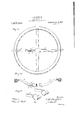
- Figure 1 is plan View of the mechanism.
- appiieci is a su'eei'ing Wheel in the normal position;
- Jig. a sectional i iew oi the invention n the line A A of Fig. 1;
- Fig. 3 is a plan view of the mechanism applied to asteering Wheel lockecl out of its normal and in Li shif eci positien;
- i is a section 5 is a section of Fig. 1 en the iin'e- C C;
- Fig. '2 is a plan View 0??
- a steering Wheel with the mechanism fanning partof the spokes 0r spicier of the 8 is a vertical seculcn of Z en ins C- D D; is a View of the meshes in a s' qeiring v ei, lche i ier 0f Wilifiii is in awe pieces; i i". 10 is s View of cal face of one t of the spider along the line E) 0i ivision; and 11 shows the overlapping enais 0f 'iKS spokes e1 Fig. :1.
- Fig. 1 en the line B;
- iii steering siisia and its upper 01' outer surface is raised and recessed at 12 and 17 to receive leaking sol-2s i3 and lug or projection 18; the other extension 01 arm is recessed at 18 in its irent end to ieceive leeking mi l3.
- Wines 1 is nl ustsbly to this head 7 by passing bolt 10 through a cap 6 communei in the s iclei' or rpelies 0i Wheel. 1 to fit snugly over the beam through the i lot 11.
- This cap is previdei th a 13 in i sides me eoirespoiu spring leek is inside leek bolt is suppo and 18 'iill p tended below e 10 iiilg" lu cured. to lie i i ward am tireugh the "01 the can in which there is n siot 3 to guide the move ment of the ii The ii 5,; mg on ssiitl'bols butting said piste 18 p1 .fieniswe belt-from protruding more than is desirable or operaiive.
- a spring is 2 arranged en leek belt 13 as to cause the to be in position at all times to recesses Tsherefor on the head as shown at 1:2
- the wheel is adapted to move along the head 7 bearing on bolt 10 sliding in slot 11.
- the wheel is moved along said head until bolt 10 rests at the lowest point in the slot, the spring lock engages the groove or recess, 12 in the top of the head, and the end of plate 18 engages the recess 17.
- the leclrbolt holds the wheel from any forward, outward or downward movement While the lower portion of the plate 18 prevents any upward or backward movement of the wheel.
- Fig. 3 the wheel 'is likewise locked and as the head increases the leverage of the wheel. on the steering shaft, the steering mechanism may be operatedwith greater ease and precision than when the wheel is in its normal position.
- a head longitudinally slotted through its vertical sides and having recesses to receive a lock-bolt and a steering member to which said head is secured;
- a head having an angular vertical section; slotted. through its vertical sides and having receases to receive aloclr belt and a steering member to-which said head is secured.
- a steering mechanism In a steering mechanism, the combination of a steering member, a head having an angular vertical section and being longitudinally slotted through its vertical sides on the end thereof, a steering. wheel having a sliding engagement with said head and means for locking the wheel in different positions on the head.
- a steering mechanism a steering member, a head with an an ular vertical, section, longitudinally slottec through its vertical sides secured thereto, a steering wheel having a sliding engagement there with and means for locking the wheel in dverent positions thereon.
- a: bolt and a steering wheel having a sliding engagement with said head and adjustabl'y secured thereto by said bolt traveling in the slot therein and locking means to'adjust the position of the wheel, on said head.
Landscapes
- Engineering & Computer Science (AREA)
- Chemical & Material Sciences (AREA)
- Combustion & Propulsion (AREA)
- Transportation (AREA)
- Mechanical Engineering (AREA)
- Tires In General (AREA)
Description
(I. M. DOUGLASS.
STEERlNG WHEEL.
APPLICATION HLEI) FEB. 25. 1915.
1 ,Q3? %89 Patented Aug. 21, 1917. v
4 SHEETS-SHEET 1- C. M. DOUGLASS.
STEERING WHEEL.
MPLlCATmN man FEB. 25. 1915.
1 23?,%89. Paiented Aug. 21, 1917.
4 SHEETS5HEET Z- Fig, 4
wucm foz C. M. DOUGLASS.
STEERING WHEEL.
APPLICATION F!LED FEB. 25,1915.
1 %?A891 P11611181 Aug. 21, 1917.
' 4 SHEETSSHEET 3.
(3111mm km 1 q vitmwoeo C. M. DOUGLASS.
STEERING WHEEL.
APPLICATION F!LED FEB. 25. 1915.
1 QWAWD Patented Aug. 21, 1917.
4 SHEETS-SHEET 4.
avwaufo'c C. M D0 uglass. /XM
@btomma To e32 whom may a nee-m:
Be it known that i, GLAUD lZOUGLAss,
e.v citizen of the United States, residing at Richfield Springs, in the State 91% New Kerk, new and useful improvements 3 lie-ls, of which the following 1 1, M es more We as mental 9e these which:
Figure 1 is plan View of the mechanism. appiieci is a su'eei'ing Wheel in the normal position; Jig. a sectional i iew oi the invention n the line A A of Fig. 1; Fig. 3 is a plan view of the mechanism applied to asteering Wheel lockecl out of its normal and in Li shif eci positien; i is a section 5 is a section of Fig. 1 en the iin'e- C C; Fig 6 i perspective view of the bent sietted steering shaft head; Fig. '2 is a plan View 0?? a steering Wheel with the mechanism fanning partof the spokes 0r spicier of the 8 is a vertical seculcn of Z en ins C- D D; is a View of the meshes in a s' qeiring v ei, lche i ier 0f Wilifiii is in awe pieces; i i". 10 is s View of cal face of one t of the spider along the line E) 0i ivision; and 11 shows the overlapping enais 0f 'iKS spokes e1 Fig. :1.
The nu nbes to same per ls tsrougneut the s -As siiewn its the upper e115. sie inei-Jseri the 0;.
of". Fig. 1 en the line B;
n u {in she end m: i; i-
much is 1n pesmen see? in the shifted sh-sin in "she varsangle she steering shaft-em: other arm or, in ether werds, is bent toward;
iii steering siisia, and its upper 01' outer surface is raised and recessed at 12 and 17 to receive leaking sol-2s i3 and lug or projection 18; the other extension 01 arm is recessed at 18 in its irent end to ieceive leeking mi l3. Wines 1 is nl ustsbly to this head 7 by passing bolt 10 through a cap 6 fermeei in the s iclei' or rpelies 0i Wheel. 1 to fit snugly over the beam through the i lot 11.
This cap is previdei th a 13 in i sides me eoirespoiu spring leek is inside leek bolt is suppo and 18 'iill p tended below e 10 iiilg" lu cured. to lie i i ward am tireugh the "01 the can in which there is n siot 3 to guide the move ment of the ii The ii 5,; mg on ssiitl'bols butting said piste 18 p1 .fieniswe belt-from protruding more than is desirable or operaiive. A spring is 2 arranged en leek belt 13 as to cause the to be in position at all times to recesses Tsherefor on the head as shown at 1:2
I do not desire liewever :0 iii ezi is the construction above described 1d shown se inst id of 21 0f ihe spider 0i" '5 shown Figs. 7 and assessable also by inze two parts as shewn When. she i positlen and the proper operation of the steering me anisin is possible in the same degree as when an ordinary steering wheel 1s used.
The wheel is adapted to move along the head 7 bearing on bolt 10 sliding in slot 11. v Vhen the wheel is moved along said head until bolt 10 rests at the lowest point in the slot, the spring lock engages the groove or recess, 12 in the top of the head, and the end of plate 18 engages the recess 17. The leclrbolt holds the wheel from any forward, outward or downward movement While the lower portion of the plate 18 prevents any upward or backward movement of the wheel. In this shifted position then, Fig. 3, the wheel 'is likewise locked and as the head increases the leverage of the wheel. on the steering shaft, the steering mechanism may be operatedwith greater ease and precision than when the wheel is in its normal position.
The operation of my invention when applied to an automobile is as follows: The driver releases the lock 13 by moving the finger lug 4 of the spring lock outward from the steering post, raises the wheel and slides it along the head until the spring lock and plate, 13 and 1S, engage the recesses 12 and 17, respectively, on the top of the head 7. The wheel will then be clear of the drivers seat andhe can move into or out of it more freely than with a fixed wheel. The wheel when locked in its shifted position. liesini a plane more or less parallel with the steering post, and the driver may guide his car with greater precision and ease by moving the wheel around the steer ing post. p
Having described my invention what I claim as new and desire to secure by Let ters Patent is:
1. In a steering mechanism, a head longitudinally slotted through its vertical sides and having recesses to receive a lock-bolt and a steering member to which said head is secured;
2. Ina steering mechanism, a head having an angular vertical section; slotted. through its vertical sides and having receases to receive aloclr belt and a steering member to-which said head is secured.
" 3. In a steering mech msm, the ccmhmaneszeee tion of a steering wheel with a lock bolt therein, a steering shaft and a steering shaft head with which the steering wheel has a sliding engagement and which has an angular vertical section and is longitudinally slotted through its vertical sides and recessed at various places to receive the said lock bolt,
' 4. In a steering mechanism, the combination of a steering member, a head having an angular vertical section and being longitudinally slotted through its vertical sides on the end thereof, a steering. wheel having a sliding engagement with said head and means for locking the wheel in different positions on the head.
5.-In a steering mechanism, a steering member, a head with an an ular vertical, section, longitudinally slottec through its vertical sides secured thereto, a steering wheel having a sliding engagement there with and means for locking the wheel in diilerent positions thereon.
6. In a steering mechanism, the combination with the steering member of a head on the end thereof and a steering wheel having a sliding engagement therewith, the spokes of which are recessed to form a slot which fits over said head and guides the wheel in its movement thereon.
7. In a steering mechanism, the combination with the steering member of a head on the end thereof and a steering wheel the spider of which is slotted throughout'opposite spokes which slot fits over said head and guides the wheel in its movement thereon.
8. In a steering tion with the steering shaft of a slotted head on the end thereof, a: bolt and a steering wheel having a sliding engagement with said head and adjustabl'y secured thereto by said bolt traveling in the slot therein and locking means to'adjust the position of the wheel, on said head.
In testimony whereof I aiiix my signature in presence of two witnesses c. M. non'enass. Witnesses:
C. G. Wmnmn, A. E. Evans.
mechanism, the com bina-
Priority Applications (1)
| Application Number | Priority Date | Filing Date | Title |
|---|---|---|---|
| US1065215A US1237489A (en) | 1915-02-25 | 1915-02-25 | Steering-wheel. |
Applications Claiming Priority (1)
| Application Number | Priority Date | Filing Date | Title |
|---|---|---|---|
| US1065215A US1237489A (en) | 1915-02-25 | 1915-02-25 | Steering-wheel. |
Publications (1)
| Publication Number | Publication Date |
|---|---|
| US1237489A true US1237489A (en) | 1917-08-21 |
Family
ID=3305308
Family Applications (1)
| Application Number | Title | Priority Date | Filing Date |
|---|---|---|---|
| US1065215A Expired - Lifetime US1237489A (en) | 1915-02-25 | 1915-02-25 | Steering-wheel. |
Country Status (1)
| Country | Link |
|---|---|
| US (1) | US1237489A (en) |
Cited By (1)
| Publication number | Priority date | Publication date | Assignee | Title |
|---|---|---|---|---|
| US2988931A (en) * | 1959-04-29 | 1961-06-20 | Grand Haven Stamped Prod | Folding steering column |
-
1915
- 1915-02-25 US US1065215A patent/US1237489A/en not_active Expired - Lifetime
Cited By (1)
| Publication number | Priority date | Publication date | Assignee | Title |
|---|---|---|---|---|
| US2988931A (en) * | 1959-04-29 | 1961-06-20 | Grand Haven Stamped Prod | Folding steering column |
Similar Documents
| Publication | Publication Date | Title |
|---|---|---|
| US2182596A (en) | Steering mechanism for automobiles and correspondingly steered vehicles | |
| US1041677A (en) | Toy. | |
| US1368959A (en) | Adjustable steering-post for automobiles | |
| US887701A (en) | Steering-gear. | |
| US1205351A (en) | Automatic adjustable draw-bar for traction-engines. | |
| US1320278A (en) | Steering-gear | |
| US1418679A (en) | Irreversible steering gear for ford cars | |
| US1290648A (en) | Indicator. | |
| US798813A (en) | Steering-gear for automobiles. | |
| US1276797A (en) | Steering-wheel. | |
| US1196616A (en) | Pedal-operated steering attachment for automobiles. | |
| US715302A (en) | Steering-gear for motor-carriages. | |
| US1112825A (en) | Way-signal or direction-indicator device. | |
| US1207693A (en) | Safety steering device. | |
| US1882323A (en) | Knee control steering attachment | |
| US1172696A (en) | Pivoted steering-wheel for automobiles. | |
| US1217419A (en) | Auto-lock. | |
| US1063952A (en) | Headlight. | |
| US1169572A (en) | Locking device for the controlling-levers of motor-vehicles. | |
| US1362428A (en) | Wheel-angle indicator | |
| US1165186A (en) | Wheel-direction indicator. | |
| US1084392A (en) | Automatic steering mechanism. | |
| US1094749A (en) | Toy. | |
| US1339246A (en) | Vehicle attachment | |
| GB191411175A (en) | Improvements in the Steering Mechanism of Motor Road Vehicles. |