US1237487A - Beveling and line-tracing planer. - Google Patents
Beveling and line-tracing planer. Download PDFInfo
- Publication number
- US1237487A US1237487A US13640416A US13640416A US1237487A US 1237487 A US1237487 A US 1237487A US 13640416 A US13640416 A US 13640416A US 13640416 A US13640416 A US 13640416A US 1237487 A US1237487 A US 1237487A
- Authority
- US
- United States
- Prior art keywords
- planer
- work
- head
- beveling
- frame
- Prior art date
- Legal status (The legal status is an assumption and is not a legal conclusion. Google has not performed a legal analysis and makes no representation as to the accuracy of the status listed.)
- Expired - Lifetime
Links
- 230000033001 locomotion Effects 0.000 description 5
- 230000008933 bodily movement Effects 0.000 description 2
- 238000010276 construction Methods 0.000 description 2
- 239000002184 metal Substances 0.000 description 1
- 108090000623 proteins and genes Proteins 0.000 description 1
- 239000002023 wood Substances 0.000 description 1
Images


Classifications
-
- B—PERFORMING OPERATIONS; TRANSPORTING
- B23—MACHINE TOOLS; METAL-WORKING NOT OTHERWISE PROVIDED FOR
- B23Q—DETAILS, COMPONENTS, OR ACCESSORIES FOR MACHINE TOOLS, e.g. ARRANGEMENTS FOR COPYING OR CONTROLLING; MACHINE TOOLS IN GENERAL CHARACTERISED BY THE CONSTRUCTION OF PARTICULAR DETAILS OR COMPONENTS; COMBINATIONS OR ASSOCIATIONS OF METAL-WORKING MACHINES, NOT DIRECTED TO A PARTICULAR RESULT
- B23Q35/00—Control systems or devices for copying directly from a pattern or a master model; Devices for use in copying manually
- B23Q35/04—Control systems or devices for copying directly from a pattern or a master model; Devices for use in copying manually using a feeler or the like travelling along the outline of the pattern, model or drawing; Feelers, patterns, or models therefor
- B23Q35/08—Means for transforming movement of the feeler or the like into feed movement of tool or work
- B23Q35/10—Means for transforming movement of the feeler or the like into feed movement of tool or work mechanically only
- B23Q35/101—Means for transforming movement of the feeler or the like into feed movement of tool or work mechanically only with a pattern composed of one or more lines used simultaneously for one tool
- B23Q35/102—Means for transforming movement of the feeler or the like into feed movement of tool or work mechanically only with a pattern composed of one or more lines used simultaneously for one tool of one line
-
- Y—GENERAL TAGGING OF NEW TECHNOLOGICAL DEVELOPMENTS; GENERAL TAGGING OF CROSS-SECTIONAL TECHNOLOGIES SPANNING OVER SEVERAL SECTIONS OF THE IPC; TECHNICAL SUBJECTS COVERED BY FORMER USPC CROSS-REFERENCE ART COLLECTIONS [XRACs] AND DIGESTS
- Y10—TECHNICAL SUBJECTS COVERED BY FORMER USPC
- Y10T—TECHNICAL SUBJECTS COVERED BY FORMER US CLASSIFICATION
- Y10T409/00—Gear cutting, milling, or planing
- Y10T409/30—Milling
- Y10T409/30084—Milling with regulation of operation by templet, card, or other replaceable information supply
Definitions
- My invention relates to wood planers and particularly to planers designed for producing curved or beveled sides upon timbers.
- the type of planer to which it has been ap plied is that in which a reciprocating carriage is employed, the same being quite gene'rally employed for dressing large timbers.
- the object of my invention is to provide a planer of the latter type with means whereby it may be used to beveltimbers and to vary the angle of the bevel at different points without stopping the operation of the planer.
- Figure 1 is a plan view of my beveling attachmentshowing a part of the planer carriage.
- Fig. 2 is an elevation of the same parts, the carriage being in transverse cross section and a part of the frame of the attachment being broken away.
- Fig. 3 is an elevation taken from across the carriage, parts of the carriage being shown in longitudinal section, but broken away directly in front of the beveling attachment.
- Fig. 4 is an end elevation and Fig. 5 a plan view of the carriage showing the means employed for canting a timber upon the carriage.
- Fig. ,6 is a section on a vertical plane through the head carrying frame.
- Fig. 7 is a sectional plan taken just above the cutter head.
- Fig. 8 is a section showingthe circular Fig.9 is a section taken just above guide rollers .55.
- I mount a side head so that it may be tilted within a considerable angle and providepmeans. for varying this angle whilev running- With this I also. employ a guide strip which is secured to the timber in a curve conforming with the curve which it is desired to give the side of the timber, and employ a guide, or guides, carried by the-head-carrying frame which enage the guide strip upon the timber to thereby determine the depth of out and thereby the bevel given the side.
- the carriage 1 is of a size to hold the largest timber to be worked upon, it is herein shown as having its bed mainly composed of timbers l0 separated by spacing blocks 11 and bound together by bolts 18. I have also shown it as having an angle bar 12-at each side the path of travel of the carriage.
- this device is installed as an attachment to a planer equipped to operate in the usualmanner, I prefer to mount the device so that it may be withdrawnwhen desired.
- a base 4 having guide ways 40 thereon which receive the feet 54: ofthe'main frame, so thatit may slide back and forth as needed. This'may be done by threaded shafts 43 which are journaled in brackets 12 of the frame 4: and thread through nuts 46 secured to or forming a part of the main frame 5. Gears 4A connect the two shafts 43 to insure like movements. One of these may be given a handle, as45.
- the main frame has two upstanding arms,
- the guide ways as shown, consists of undercut grooves in which fit the like shaped segmentlbars of :frame 6.
- the upper ends of these curved bars are connected by a bar 52, and may be otherwise connected.
- the cutter head carrying frame 6 comprisesthe tWo'circular segment bars 60 which are connected together 1n suitable manner and provided with bearings :for the cutter head shaft.
- the upperand lowerends are 'conn'e'ctechby bars 6land"62, respectively,
- I also prefer to provide a central arm or arms '63 which provide a central bearing 65.
- the cutter head 'Zl should, for the work referredto, be of considerable axial extent.
- A-driving pulley is secured on the opposite side of the central bearing.
- the central end of the cutte1.' head,'or that end which is toward theaxis of the circular segments 51, 60, being the lower as illus trated,” should extend to or j u'st beyond the axis of thesesegments.
- the axis of the segments should also-coincide with the lower, outer'finished edge of the timber.
- a guidewhich is placed upon the stick being beveled This 1 preferably consists of a strip of woo'd SOof a length to extend throughout the length'of the' stick project slightly which is to be beveled.
- the stick or timber 8 fllZLS laid out upon its surface a line representing the distance to which it is to be cutback on this side.
- the guide strip is then secured with its outer face inward from this linea distance determined by the dimensions of the guide wheels or rollers carried by the cutter head carrying frame.
- the shafts 56 are provided, each with a key'way 57 and also rollers 55.
- the shafts 56 may each be provided With a hand wheel 58 by which it maybe held when adjusting the rollers 55. With a key in the key ways of shaftand roller, the two are bound together. This is secured by inserting a key 59. By removing the key, the roller may be run up or down.
- the first thing to be done is to secure the guide strip '80 to the timber in conformity --with the amount it is desired to cut away.
- the guide wheel, or rollers, as the case may be, are then adjusted to the height of the timber. enough to maintain the guide against the strip 80. This may be easily done by operating the wheel 92. In this manner a bevel of continuously varying angle'may be formed on the timber.
- the cutter head is then tilted which produce curves of relatively short "radius, this type 'of' guidewheel'is best.
- rollers 55 are essentially aszgood.
- the beams 20 are preferably of :a metal section which has a top and'bottomflange, as a channel bar. These flanges arewprovided with a series of holes 21, those .in one beam being preferably staggered relatively to those in the other. I also prefer that those "in the lower-flange be slightly smaller than may beheld against dropping through when placed in the holes. These pins provide a backing for the timber.
- a traveling work holding carriage in combination, a traveling work holding carriage, a side head mounted for adjust ment about an axis parallel with the direction of movement of thecarriage, a flexible templet stripv adapted to be secured to the work, and a cut-regulating-roller associated with the head and engaging said templet strip to control the depth of cutting of the head.
- a work holder in combination, a work holder, a side head mounted for adjustment about an axis extending, parallel, with the length of the work, a flexible templet strip adapted to be secured directly upon the work, a presser or follower member carried conjointly with the side head, and means for securing a traversing movement between the work and the side head lengthwise of the work.
- a reciprocating work holder In a line tracing planer, a reciprocating work holder, a cutter head, a flexible templet adapted to be secured directly upon the work, and a presser or follower member carried conjointly with the cutter head and adapted to control the depth of action of the cutter head by engagement with said templet.
- a reciprocating carriage in combination, a reciprocating carriage,-a frame supported alongside the carriage to turn about an axis which parallels the direction of travel of the carriage, a cutter head mounted upon said frame with its cutting edge in a line which intersects said axis, a depth gage carried by said head and a templet strip secured to the work and engaged by said depth gage.
- a movable work supporting table in combination, a movable work supporting table, a side cutting head mounted alongside said table, a templet strip adapted to be secured to the upper surface of the work, and a cut-regulating roll carried jointly with the cutting head and positioned to engage said templet to thereby limit the depth of cut of the head.
- a movable work supporting table in combination, a movable work supporting table, a side cutting head mounted alongside said table, a templctstrip adapted to be secured to the upper surface of the work,
- a cut-regulating roll carried jointly with the cutting head and positioned to engage said templet to thereby limit the depth of cut of the head, and means'for adjusting saidroll lengthwise the cutting head.
- a beveling and line tracing planer in combination, a movable work supporting table, a side cutting head mounted alongside said table, a templet strip adapted to be secured to the upper surface ofthe work, a cut-regulating roll carried jointly with the cutting head and positioned to engage said templet to thereby limit the depth of cut of the head, and means for adjusting the axis of the cutting head while the machine is running about an axis extending parallel with the direction of movement of the carriage.
- j I I I 8.
- a line tracing planer in combination, a reciprocating work holder, a flexible templet strip adapted to be secured to" a surface ofthe work adjacent that to be dressed, a cutter head mounted for bodily movement toward and. from the work, and a depth gage mounted to move with the cutter head and adapted to engage said templet strip.
- a line tracing planer in combination, a r-eciprocating work holder, a flexible templet strip adapted to be secured to a surface of the work adjacent that to be dressed, a cutter head mounted for bodily qmovement toward and from the work, a
- depth gage mounted to move with the cutter head and adapted to engage said templet strip gage head.
- a reciprocating work holder in combination, a reciprocating work holder, a flexible templet strip adapted to be secured to a surface of the work adjacent that to be dressed, a cutter head mounted for bodily movement toward and from the work, a depth gage comprising a roller secured concentric with the cutter head and adapted to engage said lengthwise of the axis of the cutter templet strip and means for adjusting the' lengthwise the axis of the cutter depth gage head.
- a traveling work holder in combination, a traveling work holder, a frame member alongside said work holder and having two circular-segmental guides separated lengthwise of and concentric with an axis extending parallel with the direction of travel of the work holder, a cutter carrying frame having complemental circular-segmental guides having supporting engagement with those of the said frame, a toothed and means for adjusting said depth gear segment carried by said cutter carrying frame, a fixedly journaled actuating gear member engaging said gear segment, and a cutter head journaled in said adjustable frame.
- a reciprocating- Work holder in combination, a reciprocating- Work holder, a flexible tem-plet strip adapted to be secured to a surface of the Work adjacent that to be dressed, a cutter headcarrying frame mountedfor angular adjustment about an axis Which is parallel Wl'llhf the direction of travel of the Work, a cutter head having its axis parallel With a radius extending from said axis of adjustment and its active cutting edge coinciding With such radius, and means for moving said cutter head carrying frame laterally toward and from the Work.
- a beveling planeryin combination a reciprocating Work carrying table, a frame at one side of this table having guide Ways extending outward from the table, a frame mounted for movement 'on'said guidevvays and having arcuate guide Ways concentric with anaxis which extends parallel with the areciprocating Work carrying table, a frame alongside said table and having arcuate guide 'WELYS concentric with an axis which substantially coincides With a side edge of said table, a cutter-head-carrying frame mounted for adjustment on said guide Ways, a cutter head journaled on said latter frame tohave its active cutting edge radial with the axis of said guideWays and "means for adj usting saidfcutter-headcarrying frame from the opposite side of the table.
Landscapes
- Engineering & Computer Science (AREA)
- Automation & Control Theory (AREA)
- Mechanical Engineering (AREA)
- Milling, Drilling, And Turning Of Wood (AREA)
Description
G. A. DICKIE.
BEVELING AND HNE TRACING PLANER.
APPLICATION FILED 055121916.
Patented Aug. 21, 1917.
5 SHEETS.SHEET 1.
WWW
Mvenmr O OOO O@ O G. A. DlCKiE. BEVELING AND LINE TRACJNG PLANER. APPLICATION FILED DEC. 12. 1916. 1,237,47, Patented Aug. 21, 1917. 5 SHEETS-SHEET 2.
G. A. DICKIE. BEVEUNG AND LINE TRACING PLANER.
APPLICATION FILED DEC. 12. 1916. LQWASYQ Patented Aug. 21,1917. 5 SHEETS SHEET 3.
G. A. DICKIE.
BEVELING AND LINE TRACING PLANER. APPLICATION FILED DEC. 12. 1910.
Patented Aug. 21, 1917.
5 SHEETS-SHEET 4.
Q OOOOOOOOOOOOQOEU 000 00000 9( )O9 OO 60000 0 o 0 0d; bob 6o o6 oo oB o 6 G. A. DICKIE.
BEVELING AND LINE TRACING PLANER.
APPLICATION FILED DEC. 12 1916- Patented 21, 1917.
5 SH -SHEET 5.
Enron. I
enoaen A. IDICKIE, or SEATTLE, WASHINGTON.
BEVELING AND LINE-TRACING PLANER.
Specification of Letters Patent. at t ,21, 1917,
Application filed December 12, 1916. Serial No. 136,404.
To all whom it may concern.-
Be it knownthat I, GEORGE A. DICKIE, a
citizen of the United States, and resident of I the city of Seattle, county of King, and State of Washington, have invented certain new and useful Improvements in Beveling and Line-Tracing Planers, of which the following is a specification.
My invention relates to wood planers and particularly to planers designed for producing curved or beveled sides upon timbers. The type of planer to which it has been ap plied is that in which a reciprocating carriage is employed, the same being quite gene'rally employed for dressing large timbers.
The object of my invention is to provide a planer of the latter type with means whereby it may be used to beveltimbers and to vary the angle of the bevel at different points without stopping the operation of the planer.
My invention consists of the parts and combinations of parts which will be hereinafter described and then particularly pointed out in-the claims. 1
In the accompanying drawings I have illustrated my invention in the type of construction which is now preferred by me.
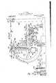
Figure 1 is a plan view of my beveling attachmentshowing a part of the planer carriage.
Fig. 2 is an elevation of the same parts, the carriage being in transverse cross section and a part of the frame of the attachment being broken away.
guides.
Fig. 3 is an elevation taken from across the carriage, parts of the carriage being shown in longitudinal section, but broken away directly in front of the beveling attachment.
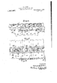
Fig. 4 is an end elevation and Fig. 5 a plan view of the carriage showing the means employed for canting a timber upon the carriage.
Fig. ,6 is a section on a vertical plane through the head carrying frame.
Fig. 7 is a sectional plan taken just above the cutter head. i
Fig. 8 is a section showingthe circular Fig.9 is a section taken just above guide rollers .55.
In certain kinds of work, as for instance in the construction of wooden ships, it is necessary to bevel the sides and edgesof very many of the timbers used and such bevels rather often Vary in angularity throughout their length. To bevel a side or-edge of a timber where the angle of the bevel is constant is easily done by tilting the shaft of aside head, but where this angle is constantly varying, something more mustv be done;
By my invention I mount a side head so that it may be tilted within a considerable angle and providepmeans. for varying this angle whilev running- With this I also. employ a guide strip which is secured to the timber in a curve conforming with the curve which it is desired to give the side of the timber, and employ a guide, or guides, carried by the-head-carrying frame which enage the guide strip upon the timber to thereby determine the depth of out and thereby the bevel given the side.
The carriage 1, is of a size to hold the largest timber to be worked upon, it is herein shown as having its bed mainly composed of timbers l0 separated by spacing blocks 11 and bound together by bolts 18. I have also shown it as having an angle bar 12-at each side the path of travel of the carriage.
Where this device is installed as an attachment to a planer equipped to operate in the usualmanner, I prefer to mount the device so that it may be withdrawnwhen desired.
To this end I then employ a base 4 having guide ways 40 thereon which receive the feet 54: ofthe'main frame, so thatit may slide back and forth as needed. This'may be done by threaded shafts 43 which are journaled in brackets 12 of the frame 4: and thread through nuts 46 secured to or forming a part of the main frame 5. Gears 4A connect the two shafts 43 to insure like movements. One of these may be given a handle, as45.
The main frame has two upstanding arms,
51 forming a circularly curved. segment of considerable extent. As shown-these are rather more than half of a circle. These are separated "length-wise the carriage and have guide ways thereon 'supon which is mounted the cutter head carrying frame 6, which is shown separately in Fig. 6.
The guide ways, as shown, consists of undercut grooves in which fit the like shaped segmentlbars of :frame 6. The upper ends of these curved bars are connected by a bar 52, and may be otherwise connected.
The cutter head carrying frame 6 comprisesthe tWo'circular segment bars 60 which are connected together 1n suitable manner and provided with bearings :for the cutter head shaft. The upperand lowerends are 'conn'e'ctechby bars 6land"62, respectively,
these-having bearings '64, =66for the shaft.
I also prefer to provide a central arm or arms '63 which provide a central bearing 65.
The cutter head 'Zl should, for the work referredto, be of considerable axial extent.
I haveshown a standard type consisting ofa block 71,-mo'unted on shaft 7 and having knives 7 2 securedto its sides. A-driving pulley is secured on the opposite side of the central bearing.
The central end of the cutte1.' head,'or that end which is toward theaxis of the circular segments 51, 60, being the lower as illus trated," should extend to or j u'st beyond the axis of thesesegments. The axis of the cutter head'and of' its shaft 7, should not be=a 'diam'eter,"'but should be ofl set enough 'to' bring the cutting sideiof the head to a diameter. The axis of the segments should also-coincide with the lower, outer'finished edge of the timber.
As a convenient means for shifting the cutter head carryingfr'ame to vary thebevel given the-side Of'tll timber, Ifhave provided the frame 6 "with a' toothed-circular segment'68'and have 'mounted an intermeshingiwo'rm 90"withina bar 52 whichiis con- .ne'ctediwith"the guideways 51. A shaft?) "hasa key -way 91, by- 'which a key associated 'with the workuvill permit free sliding of the worm on the shaft/"while binding them to turn t'ogethe'r. This feature is needed only if the' attachment is to be moved'bodily'back from the carriage.
In connection with the' "above mechanism I employ a guidewhich is placed upon the stick being beveled. This 1 preferably consists of a strip of woo'd SOof a length to extend throughout the length'of the' stick project slightly which is to be beveled. The stick or timber 8 fllZLS laid out upon its surface a line representing the distance to which it is to be cutback on this side. The guide strip is then secured with its outer face inward from this linea distance determined by the dimensions of the guide wheels or rollers carried by the cutter head carrying frame.
I have shown two types of these guide wheels, these beingeach adapted for its special conditions and capable of either being used, as may best fitthe conditions. @neof these consists of a guide wheel 7 5, which is side the cutter head. These shafts are,
threaded and-also the rollers 55. v The shafts 56 are provided, each with a key'way 57 and also rollers 55. The shafts 56 may each be provided With a hand wheel 58 by which it maybe held when adjusting the rollers 55. With a key in the key ways of shaftand roller, the two are bound together. This is secured by inserting a key 59. By removing the key, the roller may be run up or down.
The first thing to be done is to secure the guide strip '80 to the timber in conformity --with the amount it is desired to cut away.
The guide wheel, or rollers, as the case may be, are then adjusted to the height of the timber. enough to maintain the guide against the strip 80. This may be easily done by operating the wheel 92. In this manner a bevel of continuously varying angle'may be formed on the timber.
1 The 'roller directly upon the cutter head is theoretically- -m'ore accurate and correct than the rollers at each side ofthc head. For sharp variations in angle-of bevels,
The cutter head is then tilted which produce curves of relatively short "radius, this type 'of' guidewheel'is best.
Where, however, the curves are easier,"the rollers 55 are essentially aszgood.
For convenience in handling timber upon the carriage, I prefer to mount upon-the carriage a series of transversely extending bars or bunks 2, :for carrying the timbers, and to provide these with rollers 23 which above the beams 20 which form the bunks.
The beams 20 are preferably of :a metal section which has a top and'bottomflange, as a channel bar. These flanges arewprovided with a series of holes 21, those .in one beam being preferably staggered relatively to those in the other. I also prefer that those "in the lower-flange be slightly smaller than may beheld against dropping through when placed in the holes. These pins provide a backing for the timber.
If the bunks or transverse beams be pivoted, the face of the timber may be given ing the bunks. In such cases the use of the guide strip 8O and the guide rollers may be unnecessary. l r I WVhat I claim as my invention is;
in combination, a traveling work holding carriage, a side head mounted for adjust ment about an axis parallel with the direction of movement of thecarriage, a flexible templet stripv adapted to be secured to the work, and a cut-regulating-roller associated with the head and engaging said templet strip to control the depth of cutting of the head. 2. In a beveling and line tracing planer, in combination, a work holder, a side head mounted for adjustment about an axis extending, parallel, with the length of the work, a flexible templet strip adapted to be secured directly upon the work, a presser or follower member carried conjointly with the side head, and means for securing a traversing movement between the work and the side head lengthwise of the work.
'3. In a line tracing planer, a reciprocating work holder, a cutter head, a flexible templet adapted to be secured directly upon the work, and a presser or follower member carried conjointly with the cutter head and adapted to control the depth of action of the cutter head by engagement with said templet.
4c. In a beveling and line tracing planer, in combination, a reciprocating carriage,-a frame supported alongside the carriage to turn about an axis which parallels the direction of travel of the carriage, a cutter head mounted upon said frame with its cutting edge in a line which intersects said axis, a depth gage carried by said head and a templet strip secured to the work and engaged by said depth gage.
5. In a beveling and line tracing planer, in combination, a movable work supporting table, a side cutting head mounted alongside said table, a templet strip adapted to be secured to the upper surface of the work, and a cut-regulating roll carried jointly with the cutting head and positioned to engage said templet to thereby limit the depth of cut of the head.
6. In a beveling and line tracing planer, in combination, a movable work supporting table, a side cutting head mounted alongside said table, a templctstrip adapted to be secured to the upper surface of the work,
a cut-regulating roll carried jointly with the cutting head and positioned to engage said templet to thereby limit the depth of cut of the head, and means'for adjusting saidroll lengthwise the cutting head.
7. In a beveling and line tracing planer, in combination, a movable work supporting table, a side cutting head mounted alongside said table, a templet strip adapted to be secured to the upper surface ofthe work, a cut-regulating roll carried jointly with the cutting head and positioned to engage said templet to thereby limit the depth of cut of the head, and means for adjusting the axis of the cutting head while the machine is running about an axis extending parallel with the direction of movement of the carriage. j I I I 8. In a line tracing planer, in combination, a reciprocating work holder, a flexible templet strip adapted to be secured to" a surface ofthe work adjacent that to be dressed, a cutter head mounted for bodily movement toward and. from the work, and a depth gage mounted to move with the cutter head and adapted to engage said templet strip.
'9. In, a line tracing planer, in combination, a r-eciprocating work holder, a flexible templet strip adapted to be secured to a surface of the work adjacent that to be dressed, a cutter head mounted for bodily qmovement toward and from the work, a
depth gage mounted to move with the cutter head and adapted to engage said templet strip gage head.
10. In a line tracing planer, in combination, a reciprocating work holder, a flexible templet strip adapted to be secured to a surface of the work adjacent that to be dressed, a cutter head mounted for bodily movement toward and from the work, a depth gage comprising a roller secured concentric with the cutter head and adapted to engage said lengthwise of the axis of the cutter templet strip and means for adjusting the' lengthwise the axis of the cutter depth gage head.
11. In a beveling and line tracing planer, in combination, a traveling work holder, a frame member alongside said work holder and having two circular-segmental guides separated lengthwise of and concentric with an axis extending parallel with the direction of travel of the work holder, a cutter carrying frame having complemental circular-segmental guides having supporting engagement with those of the said frame, a toothed and means for adjusting said depth gear segment carried by said cutter carrying frame, a fixedly journaled actuating gear member engaging said gear segment, and a cutter head journaled in said adjustable frame.
l2. Ina beveling and line tracing planer, in combination, a traveling Work holder, a
frame member alongside said Workholder and. having two circular-segmental guides separated lengthwise of and concentric With an axis extending parallel with the direction gear segment, and a cutter head journaled in said adjustable frame to bring its cutting edge radial with the axis of adjustment.
13. In a line tracing planer, in combination, a reciprocating- Work holder, a flexible tem-plet strip adapted to be secured to a surface of the Work adjacent that to be dressed, a cutter headcarrying frame mountedfor angular adjustment about an axis Which is parallel Wl'llhf the direction of travel of the Work, a cutter head having its axis parallel With a radius extending from said axis of adjustment and its active cutting edge coinciding With such radius, and means for moving said cutter head carrying frame laterally toward and from the Work.
'14. a beveling planeryin combination, a reciprocating Work carrying table, a frame at one side of this table having guide Ways extending outward from the table, a frame mounted for movement 'on'said guidevvays and having arcuate guide Ways concentric with anaxis which extends parallel with the areciprocating Work carrying table, a frame alongside said table and having arcuate guide 'WELYS concentric with an axis which substantially coincides With a side edge of said table, a cutter-head-carrying frame mounted for adjustment on said guide Ways, a cutter head journaled on said latter frame tohave its active cutting edge radial with the axis of said guideWays and "means for adj usting saidfcutter-headcarrying frame from the opposite side of the table.
Signed at Seattle, l/Vashington, this 5th day of December, 1916. GEORGE A.-DICKIE.
Copies of this patent may be obtained for five cents each, by addressing the Commissionerof Eatents,
Washington,D. 0'. I v
Priority Applications (1)
| Application Number | Priority Date | Filing Date | Title |
|---|---|---|---|
| US13640416A US1237487A (en) | 1916-12-12 | 1916-12-12 | Beveling and line-tracing planer. |
Applications Claiming Priority (1)
| Application Number | Priority Date | Filing Date | Title |
|---|---|---|---|
| US13640416A US1237487A (en) | 1916-12-12 | 1916-12-12 | Beveling and line-tracing planer. |
Publications (1)
| Publication Number | Publication Date |
|---|---|
| US1237487A true US1237487A (en) | 1917-08-21 |
Family
ID=3305306
Family Applications (1)
| Application Number | Title | Priority Date | Filing Date |
|---|---|---|---|
| US13640416A Expired - Lifetime US1237487A (en) | 1916-12-12 | 1916-12-12 | Beveling and line-tracing planer. |
Country Status (1)
| Country | Link |
|---|---|
| US (1) | US1237487A (en) |
Cited By (6)
| Publication number | Priority date | Publication date | Assignee | Title |
|---|---|---|---|---|
| US2571861A (en) * | 1948-11-26 | 1951-10-16 | Van J Gegumis | Wood surfacing and edging machine |
| US2624242A (en) * | 1949-06-28 | 1953-01-06 | North American Aviation Inc | Profiling machine |
| US2734428A (en) * | 1956-02-14 | Universal router | ||
| US2787197A (en) * | 1954-03-22 | 1957-04-02 | Gen Dynamics Corp | Shaping machine |
| US2949948A (en) * | 1957-08-06 | 1960-08-23 | Warren B Zern | System for hanging doors |
| DE4012999A1 (en) * | 1990-04-24 | 1991-10-31 | Josef Deuschl | Work table with adjustable angle of inclination - is supported along one edge by cam |
-
1916
- 1916-12-12 US US13640416A patent/US1237487A/en not_active Expired - Lifetime
Cited By (6)
| Publication number | Priority date | Publication date | Assignee | Title |
|---|---|---|---|---|
| US2734428A (en) * | 1956-02-14 | Universal router | ||
| US2571861A (en) * | 1948-11-26 | 1951-10-16 | Van J Gegumis | Wood surfacing and edging machine |
| US2624242A (en) * | 1949-06-28 | 1953-01-06 | North American Aviation Inc | Profiling machine |
| US2787197A (en) * | 1954-03-22 | 1957-04-02 | Gen Dynamics Corp | Shaping machine |
| US2949948A (en) * | 1957-08-06 | 1960-08-23 | Warren B Zern | System for hanging doors |
| DE4012999A1 (en) * | 1990-04-24 | 1991-10-31 | Josef Deuschl | Work table with adjustable angle of inclination - is supported along one edge by cam |
Similar Documents
| Publication | Publication Date | Title |
|---|---|---|
| US1237487A (en) | Beveling and line-tracing planer. | |
| US1933798A (en) | Manufacture of propellers | |
| US572374A (en) | Rod-cutting apparatus | |
| US254202A (en) | Circular sawing machine | |
| US611599A (en) | Metal cutter and roller | |
| US1804271A (en) | Torch cutting device | |
| US1249349A (en) | Beveling and line-tracing planer. | |
| US529839A (en) | Sawing-machine | |
| US635107A (en) | Attachment for edging or ripping saws. | |
| US28818A (en) | George storer | |
| US836117A (en) | Band-saw machine. | |
| US689169A (en) | Machine for framing floor-beams | |
| US1182298A (en) | Wood-shaping machine. | |
| US6443A (en) | Machinery eos | |
| US771065A (en) | Stone-sawing machine. | |
| US779183A (en) | Dovetailing-machine. | |
| US390884A (en) | Lathe for turning wooden spirals | |
| US420886A (en) | oncken | |
| US126232A (en) | Improvement in machines for making saw-handles | |
| US1228990A (en) | Saw leveling and stretching machine. | |
| US807560A (en) | Floor-dressing machine. | |
| US1988895A (en) | Device for dressing profiled grinding wheels | |
| US83684A (en) | Ezra baily | |
| US506919A (en) | Woodworking machine | |
| US962530A (en) | Metal-cutting machine. |