US1237448A - Loading attachment for automobiles. - Google Patents
Loading attachment for automobiles. Download PDFInfo
- Publication number
- US1237448A US1237448A US11035016A US11035016A US1237448A US 1237448 A US1237448 A US 1237448A US 11035016 A US11035016 A US 11035016A US 11035016 A US11035016 A US 11035016A US 1237448 A US1237448 A US 1237448A
- Authority
- US
- United States
- Prior art keywords
- bar
- automobiles
- platform
- shaft
- loading
- Prior art date
- Legal status (The legal status is an assumption and is not a legal conclusion. Google has not performed a legal analysis and makes no representation as to the accuracy of the status listed.)
- Expired - Lifetime
Links
- 238000010276 construction Methods 0.000 description 2
- 239000011435 rock Substances 0.000 description 2
- 241000387514 Waldo Species 0.000 description 1
- HCJKXXMOOMBBPY-IEJDVFFQSA-N [2-[(8s,9s,10r,11s,13r,14s,17s)-13-formyl-11-hydroxy-10-methyl-3-oxo-1,2,6,7,8,9,11,12,14,15,16,17-dodecahydrocyclopenta[a]phenanthren-17-yl]-2-oxoethyl] acetate Chemical compound C1CC2=CC(=O)CC[C@]2(C)[C@@H]2[C@@H]1[C@@H]1CC[C@H](C(=O)COC(=O)C)[C@@]1(C=O)C[C@@H]2O HCJKXXMOOMBBPY-IEJDVFFQSA-N 0.000 description 1
- 230000000284 resting effect Effects 0.000 description 1
- 238000004804 winding Methods 0.000 description 1
Images

Classifications
-
- B—PERFORMING OPERATIONS; TRANSPORTING
- B60—VEHICLES IN GENERAL
- B60P—VEHICLES ADAPTED FOR LOAD TRANSPORTATION OR TO TRANSPORT, TO CARRY, OR TO COMPRISE SPECIAL LOADS OR OBJECTS
- B60P1/00—Vehicles predominantly for transporting loads and modified to facilitate loading, consolidating the load, or unloading
- B60P1/04—Vehicles predominantly for transporting loads and modified to facilitate loading, consolidating the load, or unloading with a tipping movement of load-transporting element
- B60P1/06—Vehicles predominantly for transporting loads and modified to facilitate loading, consolidating the load, or unloading with a tipping movement of load-transporting element actuated by mechanical gearing only
- B60P1/14—Vehicles predominantly for transporting loads and modified to facilitate loading, consolidating the load, or unloading with a tipping movement of load-transporting element actuated by mechanical gearing only with cables, chains, or the like
Definitions
- My invention relates to improvements in loading and unloading devices and has for its object to provide simply constructed means of this class which is readily appli cable to automobiles and other vehicles for easily loading and unloading heavy boxes, crates and the like.
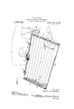
- Figure 1 is a perspective view of the improved loader applied to an automobile, showing said loader tilted rearwardly;
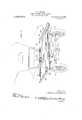
- Fig. 2 is a similar view looking from the rear of the machine.
- Fig. 3 is a perspective view showing the loading platform in its-normal position.
- the numeral 1 designates the frame of an automobile, 2 the rear wheels thereof, 3 the running boards, and 4 the rear fenders.
- a transverse horizontal hinge shaft 5 Disposed over the rear end of the frame 1 is a transverse horizontal hinge shaft 5 having a pair of depending attaching plates welded or otherwise secured thereto, said platescontacting with the outer faces of the side bars of the frame and being secured to said bars by bolts or the like 7.
- the sills 8 of a loading platform 9 are provided on their lower edges with bearings 10 which include fingers 11 straddling the ends shaft 5, removable ,pins 12 being assed through said fingers below the shaft or the purpose of forming a detachable connectlon.
- a winding shaft 13 is rotatably mounted on the front ends of the sills 8 and carries a drum 14 upon which a cable 15 is adapted to be wound to tilt the platform forwardly to a horizontal position and to permit said platform tojsilt rearwardly until it stands substantially upright.
- One endof the'eable 15 i secured at their lower ends to a suitable part of the vehicle and are provided at their up per ends with hooks 20 which take over the ends of the bar 18, which ends project beyond the frame 1.
- Vertical brace rods 21 are also provided, said rods being secured at their upper ends to the bar 18 and at their lower ends to the running boards3. .1 Additional brace rods 22 converge rearwardly from the ends of the bar 18 and are secured at their rear ends to the brackets of the,
- the bar 18 is rigidly secured in position yet done, by simply removing the pins '12, the
- crank 23 is preferably employed. Also any suitable mechanism may be used to prevent retrograde movement of the shaft in question.
- said shaft is shown as provided with a ratchet wheel 21 which cooperates with a For illustrative purposes, however,
- the dog 25 is normally moved to operative positionby/ineans of asuitable spring 26 but may be released at will by a rock shaft 27 mounted on the bar16, said shaft having a central crank 28which bears against the p inner side of the dog and being equipped with an operating crank 29 at one end.
- locking bolts 30 are secured to the front ends of the sills 8, these bolts being adapted for reception in openings in the ends of the bar 18 as shown in Fig. 1.
- Keys 31 are passed through the bolts 30 beneath the bar 1 8 and said-keys are held against acci- 85 it may be detached easily and when this IS I and eiiicient regardlessof its simplicity, it'- being obvious that the vertical flanges of the bars 34 serve to form sides for the plat form to retain boxes and the like thereon.
- the rear edge of the platform 9 is provided with a loading plate 35 adapted to be forced under the load while it rests on the ground,
- the platform is preferably provided with a pair of openings 36 which take over the rear wheels as shown in, Fig. 1.
- the improved loading attachment is adapted primarily for application to auto mobiles and is well fitted for loading and neonate unloading pianos, but it is to be understood that it may well be employed in connection with other types of vehicles and can be used for any purpose to which it is applicable.
- a drum and a ratchet wheel secured to said shaft a dog pivotally mounted on said bar for cooperation with said ratchet wheel in holdipg said shaft against retrograde movemcnt,.'a rock shaft mounted on said bar for releasing said dog, a second transverse bar in advance of the sill hinges and means for securing it in place on the vehicle frame, said second named bar carrying a sheave and receiving the front ends of said sills on its ends, a cable passing around said sheave and secured at one end to said first named bar and at its other end to saiddrum, and
Landscapes
- Engineering & Computer Science (AREA)
- Transportation (AREA)
- Mechanical Engineering (AREA)
- Fittings On The Vehicle Exterior For Carrying Loads, And Devices For Holding Or Mounting Articles (AREA)
Description
W A. ATWOOD.
LOADING ATTACHMENT FOR AUTOMOBILES.
APPLICATION FILED JULY 20. 1916- I 1,237,48= Patented Aug. 21, 1917.
3 SHEETS-SHEET 1.
w. A. ATWOOD. LOADING ATTACHMENT FOR AUTOMOBILES.
' APPLICATION FILED JULY 20.1916- 7 1,23%44, Patented Aug. 21, 1917.-
3 SHEETS- SHEET 2.
avmmmtoz w. A. ATWOOD. LT ADING ATTACHMENT FOR AUTOMOBILES.
APPLICATION FILED JULY 20.1916.
Patented Aug. 21, 1917.
3 SHEETSSHEET 3.
mwmtoz yaw/0 @flM/Wgd WALDO A. ATWOOD, 0F VJ ZLLISCA, IOWA.
LOADING ATTACHMENT FOR AUTOMOBILES.
clare the following to be a full, clear, and exact description of the invention, such as will enable others skilled in the art to which it appertains to make and use the same.
My invention relates to improvements in loading and unloading devices and has for its object to provide simply constructed means of this class which is readily appli cable to automobiles and other vehicles for easily loading and unloading heavy boxes, crates and the like.
With the foregoing general object in view, the invention resides in certain novel features of construction and in unique combinations of parts to be hereinafter fully described and claimed, the descriptive matter being supplemented by the accompanying drawings which constitute a part of this application and in which:
Figure 1 is a perspective view of the improved loader applied to an automobile, showing said loader tilted rearwardly;
Fig. 2 is a similar view looking from the rear of the machine; and,
Fig. 3 is a perspective view showing the loading platform in its-normal position.
In specifically describing the structure shown in the drawings above briefly described, similar characters will be employed to designate corresponding parts throughout the several views and reference will be herein made to the numerous elements by their respective ind-ices. To this end, the numeral 1 designates the frame of an automobile, 2 the rear wheels thereof, 3 the running boards, and 4 the rear fenders.
Disposed over the rear end of the frame 1 is a transverse horizontal hinge shaft 5 having a pair of depending attaching plates welded or otherwise secured thereto, said platescontacting with the outer faces of the side bars of the frame and being secured to said bars by bolts or the like 7. The sills 8 of a loading platform 9 are provided on their lower edges with bearings 10 which include fingers 11 straddling the ends shaft 5, removable ,pins 12 being assed through said fingers below the shaft or the purpose of forming a detachable connectlon.
' for rotating of the Specification of Letters Patent. Patented Aug, 21, 1917, Application filed July 20, 1916. Serial No. 110,350. i i
A winding shaft 13 is rotatably mounted on the front ends of the sills 8 and carries a drum 14 upon which a cable 15 is adapted to be wound to tilt the platform forwardly to a horizontal position and to permit said platform tojsilt rearwardly until it stands substantially upright. One endof the'eable 15 i secured at their lower ends to a suitable part of the vehicle and are provided at their up per ends with hooks 20 which take over the ends of the bar 18, which ends project beyond the frame 1. Vertical brace rods 21 are also provided, said rods being secured at their upper ends to the bar 18 and at their lower ends to the running boards3. .1 Additional brace rods 22 converge rearwardly from the ends of the bar 18 and are secured at their rear ends to the brackets of the,
fenders 4. By these features of construction, I
the bar 18 is rigidly secured in position yet done, by simply removing the pins '12, the
entire platform may be removed from vehicle frame. p
Any preferred means may be provided crank 23 is preferably employed. Also any suitable mechanism may be used to prevent retrograde movement of the shaft in question. said shaft is shown as provided with a ratchet wheel 21 which cooperates with a For illustrative purposes, however,
the
so the shaft 13 but a detachable dog .pivotally mounted on the bar 16.
The dog 25 is normally moved to operative positionby/ineans of asuitable spring 26 but may be released at will by a rock shaft 27 mounted on the bar16, said shaft having a central crank 28which bears against the p inner side of the dog and being equipped with an operating crank 29 at one end.
For holding the platform in lowered posi tion, locking bolts 30 are secured to the front ends of the sills 8, these bolts being adapted for reception in openings in the ends of the bar 18 as shown in Fig. 1. Keys 31 are passed through the bolts 30 beneath the bar 1 8 and said-keys are held against acci- 85 it may be detached easily and when this IS I and eiiicient regardlessof its simplicity, it'- being obvious that the vertical flanges of the bars 34 serve to form sides for the plat form to retain boxes and the like thereon. The rear edge of the platform 9 is provided with a loading plate 35 adapted to be forced under the load while it rests on the ground,
and for the purpose of permitting the platform to tilt rearwardly to the necessary extent for allowing said plate to operate in this manner, the platform is preferably provided with a pair of openings 36 which take over the rear wheels as shown in, Fig. 1.
In operation, with the platform. standing in its normal horizontal position, the pins 32 and keys 31. may be removed, and by actuating the crank 29 the dog 25 will be released. This will permit the shaft 13 to rotate freely to pay out the cable 15, thus permitting the platform 9 to assume a substantially upright position with the loading plate 35 resting on the ground or street. The box or the like to be loaded is now tilted rearwardly to permit the loading plate to be inserted beneath it and is then rocked forwardly until it rests on the platform 9. The drum 14 is now rotated by means of the shaft 13 and crank 23 to wind the cable 15, thus returning the platform to its normal position, in which position it is locked by means of the keys 31 and-pins 32. The unloadin operation is of course the reversal of the oading and may be performed with equal ease,
The improved loading attachment is adapted primarily for application to auto mobiles and is well fitted for loading and neonate unloading pianos, but it is to be understood that it may well be employed in connection with other types of vehicles and can be used for any purpose to which it is applicable.
In the foregoing l have described certain specific details for accomplishing probably the best results and in the accompanying front ends of the sills in advance of said bar,
, a drum and a ratchet wheel secured to said shaft, a dog pivotally mounted on said bar for cooperation with said ratchet wheel in holdipg said shaft against retrograde movemcnt,.'a rock shaft mounted on said bar for releasing said dog, a second transverse bar in advance of the sill hinges and means for securing it in place on the vehicle frame, said second named bar carrying a sheave and receiving the front ends of said sills on its ends, a cable passing around said sheave and secured at one end to said first named bar and at its other end to saiddrum, and
means for locking the front ends of said sills to said second bar.
In testimony whereof I have hereunto set my hand in the presence of two subscribing witnesses.
W ALDO A. ATWOOD.
Witnesses:
F. L NGMAN, S. H Cowman
Priority Applications (1)
| Application Number | Priority Date | Filing Date | Title |
|---|---|---|---|
| US11035016A US1237448A (en) | 1916-07-20 | 1916-07-20 | Loading attachment for automobiles. |
Applications Claiming Priority (1)
| Application Number | Priority Date | Filing Date | Title |
|---|---|---|---|
| US11035016A US1237448A (en) | 1916-07-20 | 1916-07-20 | Loading attachment for automobiles. |
Publications (1)
| Publication Number | Publication Date |
|---|---|
| US1237448A true US1237448A (en) | 1917-08-21 |
Family
ID=3305267
Family Applications (1)
| Application Number | Title | Priority Date | Filing Date |
|---|---|---|---|
| US11035016A Expired - Lifetime US1237448A (en) | 1916-07-20 | 1916-07-20 | Loading attachment for automobiles. |
Country Status (1)
| Country | Link |
|---|---|
| US (1) | US1237448A (en) |
-
1916
- 1916-07-20 US US11035016A patent/US1237448A/en not_active Expired - Lifetime
Similar Documents
| Publication | Publication Date | Title |
|---|---|---|
| US5297912A (en) | Ladder rack for motor vehicles | |
| US2332326A (en) | Two-wheeled trailer | |
| US3713553A (en) | Folding multiposition loading ramp for trucks having tail gates | |
| US3843002A (en) | Boat and trailer loading device | |
| US3797681A (en) | Apparatus for mounting a winch on a trailer | |
| US5267779A (en) | Pick up truck conversion dumping body | |
| US1237448A (en) | Loading attachment for automobiles. | |
| US2715470A (en) | Automotive wreck tow trucks | |
| US1654032A (en) | Dumping apparatus | |
| US1864829A (en) | Spare tire carrier for road vehicles | |
| US1561157A (en) | Trailer unloading mechanism | |
| US3149739A (en) | Auxiliary loading container for vehicles | |
| KR100839897B1 (en) | Easy to load trailer | |
| US1312489A (en) | Planoohaph cik | |
| US1496141A (en) | Double-platform automobile and wagon dump | |
| US1391607A (en) | Loading and unloading apparatus for vehicles | |
| US1113408A (en) | Hoisting mechanism. | |
| US218999A (en) | Improvement in dumping-wagons | |
| KR980007432U (en) | Dumping device of freight vehicle | |
| US1369011A (en) | Device for loading and unloading vehicles | |
| US1443749A (en) | Lumber-carrying vehicle | |
| US1355690A (en) | Automobile-hoist | |
| US904793A (en) | Dumping-wagon. | |
| US532785A (en) | Dumping-wagon | |
| US787934A (en) | Dumping-wagon. |