US1237373A - Internal-combustion engine. - Google Patents
Internal-combustion engine. Download PDFInfo
- Publication number
- US1237373A US1237373A US82055814A US1914820558A US1237373A US 1237373 A US1237373 A US 1237373A US 82055814 A US82055814 A US 82055814A US 1914820558 A US1914820558 A US 1914820558A US 1237373 A US1237373 A US 1237373A
- Authority
- US
- United States
- Prior art keywords
- cylinder
- piston
- head
- air
- crosshead
- Prior art date
- Legal status (The legal status is an assumption and is not a legal conclusion. Google has not performed a legal analysis and makes no representation as to the accuracy of the status listed.)
- Expired - Lifetime
Links
- 238000002485 combustion reaction Methods 0.000 title description 13
- 230000002000 scavenging effect Effects 0.000 description 15
- 238000012856 packing Methods 0.000 description 8
- 238000010276 construction Methods 0.000 description 6
- 238000005266 casting Methods 0.000 description 5
- 230000006835 compression Effects 0.000 description 4
- 238000007906 compression Methods 0.000 description 4
- 210000004907 gland Anatomy 0.000 description 3
- 210000000707 wrist Anatomy 0.000 description 3
- 230000000694 effects Effects 0.000 description 2
- 238000010304 firing Methods 0.000 description 2
- 239000000446 fuel Substances 0.000 description 2
- 239000000463 material Substances 0.000 description 2
- RYGMFSIKBFXOCR-UHFFFAOYSA-N Copper Chemical compound [Cu] RYGMFSIKBFXOCR-UHFFFAOYSA-N 0.000 description 1
- 210000000038 chest Anatomy 0.000 description 1
- 239000000498 cooling water Substances 0.000 description 1
- 229910052802 copper Inorganic materials 0.000 description 1
- 239000010949 copper Substances 0.000 description 1
- 239000007789 gas Substances 0.000 description 1
- 239000002184 metal Substances 0.000 description 1
- 229910052751 metal Inorganic materials 0.000 description 1
- 238000005192 partition Methods 0.000 description 1
- 238000007789 sealing Methods 0.000 description 1
- 238000000926 separation method Methods 0.000 description 1
- 230000000153 supplemental effect Effects 0.000 description 1
- XLYOFNOQVPJJNP-UHFFFAOYSA-N water Substances O XLYOFNOQVPJJNP-UHFFFAOYSA-N 0.000 description 1
Images


Classifications
-
- F—MECHANICAL ENGINEERING; LIGHTING; HEATING; WEAPONS; BLASTING
- F02—COMBUSTION ENGINES; HOT-GAS OR COMBUSTION-PRODUCT ENGINE PLANTS
- F02B—INTERNAL-COMBUSTION PISTON ENGINES; COMBUSTION ENGINES IN GENERAL
- F02B25/00—Engines characterised by using fresh charge for scavenging cylinders
Definitions
- the device is applicable to any single acting engine in which scavenging by compressed air is desirable.
- the device comprises in addition to the usual parts of a single actingengine, a combined crosshead and supplemental piston, connected by a rod to the main piston; a combined cylinder ⁇ and crosshead guide, a head closing the head end of the combined crosshead guide and cylinder andthe crank end of the main cylinder; a distributin valve mechanism to cause these two cylin er spaces to serve as a double acting air compresser, and suitable means for admitting air compressed thereby to the head end space of the main cylinder at proper times for scavenging the same.
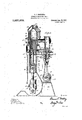
- Figure 1 is a vertical axial section through one of the cylinders, the plane of section being transverse to the shaft and the piston being shown 'in its compression stroke.
- y Fig. 2 is -a view similar to Fig'. ⁇ 1 showin the piston at the crank end dead point an .indicating the flow of air in the scavenging action.
- Fig. 3 ⁇ is a vertical axial section on a plane passing through the axis ofthe shaft the front half of the combined .crossheadguide and cylinder being removed;
- Fig. 4 is ay section on the line of Fig. 1;
- Fig. 5 is a section on the line 5-5 of Fig. 1; y y Fig. is a fragmentary view showing the mode 'of assembling the intermediate cylinder head and crosshead guide, the front half of the guide being released and part'ially withdrawn;
- Fig. 7 is a fragmentary View looking down on the cylinder head in Fig 6;
- Fig. 8 is a Asection on the line 8-8 of Fig; 6; A
- Fi 9 is an axial section of the combined cross ead and piston vshowing it separated to release the wrist pin;
- FIGs. 10 and 11 are fragmentary views of a 'modified construction of the cylinder, zlroshead guide and intermediate cylinder A two cylinder engine is illustrated but it is to be understood that the invention is applicable to engines of any number of cylinders. Y
- the engine is supported on a base casting 11 having crank shaft bearings 12 for the crank shaft 13.
- the main frame 14 is carried directly on the basecasting 11 andis braced by stanchions 15.
- the main frame 14 carriesthe crosshead guides which are in the form of divided cylinders. These are made up of portionsl formed directly on the frame 414 and removable portions 17 held thereto by bolts 18, the two parts fitting closely to make an air tight joint so that thek guide may serve as an air compressor cylinder.
- the working cylinders 19 are mounted on the top of frame 14 and are surrounded by Water jackets 20.
- Each cylinder has a scavenging air port 21 and exhaust ports 22 leading to the exhaust connection 23 for the usual exhaust manifold (not shown).
- Each cylinder is provided with a jacketed head 24 having a fuel feed device 25 which is not illustrated in detail and which may be of any form adapted to this use.
- a fuel feed device 25 which is not illustrated in detail and which may be of any form adapted to this use.
- An air starting valve is indicated generally at '26, but this is not illustrated in detail for similar reasons. l.
- the crosshead guide and the cylinder 19 are coaxial andthe main piston 27 is connected to the combined crosshead and piston 28 by ay hollow rod 29.
- the main piston 27 has the usual packing rings 30 and is cored out for the passage of cooling water which is supplied Iin the usual manner through the rod 29.
- the water connections to the rod 29 are omitted as not material to this invention, but they may be made by means of passages through the crosshead 28 and telescopic pipe connections thereto.
- the crossheads 28 are each made in two parts, the plane of separation being on the axis of the wrist pin 31.
- the rods 29 each end in flange 32 and bolts 33 passing through the flange 32-and both portions of the corresponding crosshead provide for ready assembly.
- the connecting r0ds-34 are 4of the usual form as are the piston packing plate 38.
- the bolts36 hold the castings 37 together and the follower plates are held thereto by screws or studs 39.
- the castings 37 when bolted together form a cylinder head having a packing gland 40 for the rod 29 and a groove for a packing ring 41.
- the plates 38 are formed with projections to enter gland 40 and exert the necessary pressure on the packing.
- the plates 38 also retain ring 41 while permitting ready removal.
- the cylinder head is threaded at 42 to receive a ring or nut 43 also made in two parts bolted together.
- a groove is provided to receive a packing ring 44 of copper or other soft metal.
- A. bayonet slot 45 is formed in the head to coact with a pin 46 at v the lower end of the main cylinder.
- Air ports 47 and 48 lead from the cylinder spaces to reciprocating distributing valves 49, one for eachA cylinder unit in the engine, mounted in valve chests 50 which are bolted to the frame 14.
- the particular form of the distributing valve is not material and any other type of valve may be used if preferred.
- Figs. 10 and 11 show a modified construction of the cylinder head.
- the combined cylinder and crosshead guide 16a is not divided and is of smaller bore than the main cylinder 19 giving a shoulder 60 against which is seated a head 37 a. This is made of two parts bolted together to facilitate removal from the rod 29.?
- the head 37 a is held seated against shoulder 60 and packing 61 by a plurality of studs 62 arranged at regular intervals around the cylinder and having check nuts 63.
- the frame 14 is continu- .ous up to cylinder casting 19, when this modified construction .is used and the head 37 is drawn out through the head end of the main cylinder together with piston 27 and rod 29 after backing out studs 62 and releasing the connecting rod.
- the modified construction parts substantially identical with those of the preferred construction bear the same reference numerals.
- the engine shownf is designed to run on the familiar two stroke cycle and on the Diesel or slow combustion rinciple.
- the cycle for each cylinder is as ollows:
- the air above the piston 27 is compressed sufficiently. by the upward movement. of the piston to ignite the fuel when this is sprayed into it at or near the head end dead point. rThe expansion of the products of combustion forces the piston down until it overtravels ports 22 and they are exhausted. Shortly after the beginning of the exhaust the piston also overtravels port 21 admitting a blast of fresh air to the cylinder, to sweep out the spent gases and fill the cylinder with fresh air.
- This air is furnished by the cylinder driven from the crank shaft and connected spaces be ⁇ low piston 27 and above thev combined crosshead and piston acting as a double acting pump.
- connectionsl adapted to conduct air compressed thereby to said scavenging air port.
- a ⁇ two part cylinder head adapted to be assembled around apiston rod; means adapted to clamp said head in position between the crank'end of the double acting cylinder and of the double acting cylinder by internal combustion; a distributing valve driven from the crank shaft and connected with the remaining two cylinder spaces to operate them as air compressing pumps; and means for admitting air compressed thereby to the head-end space of the double acting cylinder during exhaust therefrom to effect scavenging of said space.
Landscapes
- Engineering & Computer Science (AREA)
- Chemical & Material Sciences (AREA)
- Combustion & Propulsion (AREA)
- Mechanical Engineering (AREA)
- General Engineering & Computer Science (AREA)
- Cylinder Crankcases Of Internal Combustion Engines (AREA)
Description
B. VNORDBERG.
INTERNAL COMUSTION` ENGINE. APPucATloN min FEB.24. |914.
Aww,
wila/wow B. V. NORDBE'RG.
INTERNAL comsusnow ENGINE.
Pasemos mso 55s. 24. 1914. Y 373 ,Y Patented Aug. 21, 1917 .4 SHEETS-SHEET 2.
s. v. NQRDBERG.V
INTERNAL CUMBUSTION ENGINE.
APPuc/Tlon FILED rss. 24, 19m.
1,237,373. n Patented mig. 21,1%?.
4 SHEETS-SHEET 3.
WH zones 65 A 1 g M :I I l B. V. NORDBERG.
INTERNAL coMusTloN ENGINE.
`APPLIKIATNNI FILED FEB. 241.19i4.
4 SHEETS-SHEET 4. 46 179,6; 45 3? 40 44 5 60 j /aff BRUNO V. NORDBERG, OF MILWAUKEE, WISCONSIN.
INTERNALCOMBUSTION ENGINE.
.Specicationof Letters Patent.
Patented Aug. 21, 1917.
Application led February 24, 1914. Serial No. 820,558.
To all ycchom t may concern.'
Beit known that I, BRUNO V. NoRnBERG,
l a citizen of the United States, residing at the cylinder at the end of the working stroke. `While attaining itsgreatest utility in the ield specified the device is applicable to any single acting engine in which scavenging by compressed air is desirable.
Broadly stated the device comprises in addition to the usual parts of a single actingengine, a combined crosshead and supplemental piston, connected by a rod to the main piston; a combined cylinder` and crosshead guide, a head closing the head end of the combined crosshead guide and cylinder andthe crank end of the main cylinder; a distributin valve mechanism to cause these two cylin er spaces to serve as a double acting air compresser, and suitable means for admitting air compressed thereby to the head end space of the main cylinder at proper times for scavenging the same. Practical embodiments of the invention are illustrated in the accompanying drawing, 'in which Figure 1 is a vertical axial section through one of the cylinders, the plane of section being transverse to the shaft and the piston being shown 'in its compression stroke. y Fig. 2 is -a view similar to Fig'.` 1 showin the piston at the crank end dead point an .indicating the flow of air in the scavenging action. p
Fig. 3` is a vertical axial section on a plane passing through the axis ofthe shaft the front half of the combined .crossheadguide and cylinder being removed;
Fig. 4 is ay section on the line of Fig. 1;
Fig. 5 is a section on the line 5-5 of Fig. 1; y y Fig. is a fragmentary view showing the mode 'of assembling the intermediate cylinder head and crosshead guide, the front half of the guide being released and part'ially withdrawn;
Fig. 7 is a fragmentary View looking down on the cylinder head in Fig 6;
Fig. 8 is a Asection on the line 8-8 of Fig; 6; A
Fi 9 is an axial section of the combined cross ead and piston vshowing it separated to release the wrist pin; and
. Figs. 10 and 11 are fragmentary views of a 'modified construction of the cylinder, zlroshead guide and intermediate cylinder A two cylinder engine is illustrated but it is to be understood that the invention is applicable to engines of any number of cylinders. Y
The engine is supported on a base casting 11 having crank shaft bearings 12 for the crank shaft 13. The main frame 14 is carried directly on the basecasting 11 andis braced by stanchions 15. The main frame 14 carriesthe crosshead guides which are in the form of divided cylinders. These are made up of portionsl formed directly on the frame 414 and removable portions 17 held thereto by bolts 18, the two parts fitting closely to make an air tight joint so that thek guide may serve as an air compressor cylinder.
1 The working cylinders 19 are mounted on the top of frame 14 and are surrounded by Water jackets 20. Each cylinder has a scavenging air port 21 and exhaust ports 22 leading to the exhaust connection 23 for the usual exhaust manifold (not shown). Each cylinder is provided with a jacketed head 24 having a fuel feed device 25 which is not illustrated in detail and which may be of any form adapted to this use. As the construction kof this device is not a part of the present invention and as `many such are known in theart, I have thought it suflicient to illustrate it diagrammatically. An air starting valve is indicated generally at '26, but this is not illustrated in detail for similar reasons. l.
The crosshead guide and the cylinder 19 are coaxial andthe main piston 27 is connected to the combined crosshead and piston 28 by ay hollow rod 29. The main piston 27 has the usual packing rings 30 and is cored out for the passage of cooling water which is supplied Iin the usual manner through the rod 29. The water connections to the rod 29 are omitted as not material to this invention, but they may be made by means of passages through the crosshead 28 and telescopic pipe connections thereto.
The crossheads 28 are each made in two parts, the plane of separation being on the axis of the wrist pin 31. The rods 29 each end in flange 32 and bolts 33 passing through the flange 32-and both portions of the corresponding crosshead provide for ready assembly. The connecting r0ds-34 are 4of the usual form as are the piston packing plate 38. The bolts36 hold the castings 37 together and the follower plates are held thereto by screws or studs 39. The castings 37 when bolted together form a cylinder head having a packing gland 40 for the rod 29 and a groove for a packing ring 41. The plates 38 are formed with projections to enter gland 40 and exert the necessary pressure on the packing. The plates 38 also retain ring 41 while permitting ready removal. The cylinder head is threaded at 42 to receive a ring or nut 43 also made in two parts bolted together. A groove is provided to receive a packing ring 44 of copper or other soft metal. A. bayonet slot 45 is formed in the head to coact with a pin 46 at v the lower end of the main cylinder.
In assembling thel engine the piston 27 with its rod 29 are put in place. The portion 17 of the crosshead guide having been removed, the connecting rod 34, crosshead 28, wrist pin 31 and rod 29are assembled and connected by the bolts 33. The two head castings 37 are then bolted together around rod 29 and the ring 44 is put in place, after which the head may be held up by engaging pin 46 in bayonet slot 45. The
the inlet ports l57 and is discharged through the connections 58 to a combined manifold and receiver 59 from which it flows to the scavenging orts 21 of the various cylinders. The air is a itted to scavenge the cylinders by the overtravel of the ports 21 by piston 27. This occurs at such a point that the scavenging port is open for about a quarter of a revolution permitting thorough scavenging. This, together with the relatively large volume of air handled secures thorough scavenging. Y
In one and two cylinder engines an enlarged receiver space is required but when more cylinders are used this may be reduced in volume. In a four cylinder engine the scavenging ports are open one after another in virtual continuity and no receiver space beyond the ordinary pipe manifold is required.
Figs. 10 and 11 show a modified construction of the cylinder head. The combined cylinder and crosshead guide 16a is not divided and is of smaller bore than the main cylinder 19 giving a shoulder 60 against which is seated a head 37 a. This is made of two parts bolted together to facilitate removal from the rod 29.? The head 37 a is held seated against shoulder 60 and packing 61 by a plurality of studs 62 arranged at regular intervals around the cylinder and having check nuts 63. The frame 14 is continu- .ous up to cylinder casting 19, when this modified construction .is used and the head 37 is drawn out through the head end of the main cylinder together with piston 27 and rod 29 after backing out studs 62 and releasing the connecting rod. In the modified construction parts substantially identical with those of the preferred construction bear the same reference numerals.
The engine shownfis designed to run on the familiar two stroke cycle and on the Diesel or slow combustion rinciple. The cycle for each cylinder is as ollows: The air above the piston 27 is compressed sufficiently. by the upward movement. of the piston to ignite the fuel when this is sprayed into it at or near the head end dead point. rThe expansion of the products of combustion forces the piston down until it overtravels ports 22 and they are exhausted. Shortly after the beginning of the exhaust the piston also overtravels port 21 admitting a blast of fresh air to the cylinder, to sweep out the spent gases and fill the cylinder with fresh air. This air is furnished by the cylinder driven from the crank shaft and connected spaces be`low piston 27 and above thev combined crosshead and piston acting as a double acting pump.
Having thusdescribed my invention, what I claim is y:-
1. In an internal combustion engine the combination of a double actingcylinder and a single acting cylinder arranged in tandem; a piston in the double acting cylinder; a combinedpiston-crosshead in the single acting cylinder; a rod connecting said piston and piston-,crosshead; a crank shaft; crank connections between said shaft and pistoncrosshead;-means adapted to operate the head-end space of the double acting cylinder by internal combustion; a valve mechanism connected with the remaining two cylinder spaces to cause them to operate as air compressing pumps; and means adapted to admit air compressed thereby to the head-end space of the double acting cylinder only during exhaust therefrom to eHect scavenging of said space.
2. In an internal combustion engine the combination of a double acting cylinder and a single acting cylinder arranged in tandem; a removable cylinder head closing the crank end of the double acting cylinder and the head-end of the single actingcylinder; a piston inthe double acting cylinder; a combined piston-crosshead inthe single acting cylinder; a rod connecting said piston and piston-crosshead; a crank shaft; crank coni nections between said shaft and piston-crosshead; means adapted to operate the headend space ofthe double4 acting cylinder by internal combustion; a distributing valve cylinder arranged in tandem therewithya removable cylinder head closing the crank end of the double acting cylinder and the head-end of the single acting cylinder; a piston in the double acting cylinder adapted to control the scavenging and exhaust ports thereof by overtraveling the same; a combined piston-crossheadin the single acting i cylinder; al rod connecting .said piston and Jpiston-c,rosshead.; a crank shaft; crank connections between said shaft and piston-.crosshead; meansadapted -to operate the'head end space of 4the double acting cylinder by internal combustion; a distributing valve ydriven from the crank shaft and connected with the remaining two cylinder spaces to operate them as air compressing pumps; and
connectionsl adapted to conduct air compressed thereby to said scavenging air port.
4. In .an internal combustion engine the combination of a double acting cylinder and a single acting cylinder arranged in tandem;
a` two part cylinder head adapted to be assembled around apiston rod; means adapted to clamp said head in position between the crank'end of the double acting cylinder and of the double acting cylinder by internal combustion; a distributing valve driven from the crank shaft and connected with the remaining two cylinder spaces to operate them as air compressing pumps; and means for admitting air compressed thereby to the head-end space of the double acting cylinder during exhaust therefrom to effect scavenging of said space.
5. In an internal combustion engine, the
combination of a double acting cylinder; a single acting cylinder formed in two longidinally separable parts, spaced from the double acting cylinder and in tandem therewith; a sectional cylinder head clamped between the two parts of said single acting cylinder; a threaded locking device adapted to urge said head into sealing relation with the adjacent crank end of the double acting cylinder; suitable packing for the joints between said head and cylinders; a piston in the double acting cylinder; a combined piston-crosshead in thesingle acting cylinder;
,a rod passing through said sectional cylinder v'head and connecting" said piston and piston crosshead; a crank shaft; crank connections between said shaft and pistoncrosshead; means adapted to operate the head-end space ofthe double acting cylinder by internal combustion; a valve mechanism "connected with the remaining two cylinder spaces to cause them to operate as air compressing pumps; and means adapted to admit air compressed thereby to the head-end space of the double acting cylinder during exhaust therefrom to effect scavenging of said space.
6. In an internal combustion engine the combination of a supporting frame; a multiple-throw crank shaft; an air manifold; and a plurality of power units mounted on said frame and each comprising the following elements, al double acting cylinder and a single'acting cylinder arranged in tandem,`
a piston in the double acting cylinder, a
combined piston-crosshead in the single acting cylinder, a rod connecting said piston and pistonfcr'os'shead, crank connections between said crank shaft and piston-crosshead, mechanism adapted to operate the head-end space of the` double acting cylinder by inter- 11a-1 combustioma vdistributing valve driven from said crank shaftland connected with the remaining two cylinder spaces to operate them as air'coinpressing pumps, discharge connections from said valve to said air manifold and connections between said manifold and the head-end space of the double acting cylinder adapted to conduct air to said space for scavenging purposes only during exhaust from said space- 7. In a twocycle engine, a pair of cylinders, a partition member and a pair of connected pistons in each cylinder dividing the cylinder into two compression chambers and a firing chamber, a crank shaft to which said pistons are connected, means for admitting fresh air to the' compression chambers, and means for conveying the air compressed in two compression chambers in unison to one firing chamber.
In testimony whereof I have signed my name to this specification in the presence of two subscribing witnesses.
BRUNO v. NORDBERG.
Witnesses:
E. C. BAYERLJM," H. W. Dow.
Priority Applications (1)
| Application Number | Priority Date | Filing Date | Title |
|---|---|---|---|
| US82055814A US1237373A (en) | 1914-02-24 | 1914-02-24 | Internal-combustion engine. |
Applications Claiming Priority (1)
| Application Number | Priority Date | Filing Date | Title |
|---|---|---|---|
| US82055814A US1237373A (en) | 1914-02-24 | 1914-02-24 | Internal-combustion engine. |
Publications (1)
| Publication Number | Publication Date |
|---|---|
| US1237373A true US1237373A (en) | 1917-08-21 |
Family
ID=3305192
Family Applications (1)
| Application Number | Title | Priority Date | Filing Date |
|---|---|---|---|
| US82055814A Expired - Lifetime US1237373A (en) | 1914-02-24 | 1914-02-24 | Internal-combustion engine. |
Country Status (1)
| Country | Link |
|---|---|
| US (1) | US1237373A (en) |
Cited By (6)
| Publication number | Priority date | Publication date | Assignee | Title |
|---|---|---|---|---|
| US2449262A (en) * | 1943-02-04 | 1948-09-14 | Weigel Daniel Michel | Valve arrangement for external-combustion engines |
| US2511905A (en) * | 1950-06-20 | Two-cycle multiple cylinder diesel | ||
| US4724800A (en) * | 1986-08-15 | 1988-02-16 | Southwest Research Institute | Ringless piston engine |
| US20080066375A1 (en) * | 2006-09-19 | 2008-03-20 | Roos Joseph W | Diesel fuel additives containing cerium or manganese and detergents |
| US20080098644A1 (en) * | 2006-09-19 | 2008-05-01 | Afton Chemical Corporation | Conductivity improving combination of cerium oxide and detergents for diesel fuels |
| US20090307967A1 (en) * | 2006-04-06 | 2009-12-17 | Oxonica Energy Ltd | Biofuel |
-
1914
- 1914-02-24 US US82055814A patent/US1237373A/en not_active Expired - Lifetime
Cited By (6)
| Publication number | Priority date | Publication date | Assignee | Title |
|---|---|---|---|---|
| US2511905A (en) * | 1950-06-20 | Two-cycle multiple cylinder diesel | ||
| US2449262A (en) * | 1943-02-04 | 1948-09-14 | Weigel Daniel Michel | Valve arrangement for external-combustion engines |
| US4724800A (en) * | 1986-08-15 | 1988-02-16 | Southwest Research Institute | Ringless piston engine |
| US20090307967A1 (en) * | 2006-04-06 | 2009-12-17 | Oxonica Energy Ltd | Biofuel |
| US20080066375A1 (en) * | 2006-09-19 | 2008-03-20 | Roos Joseph W | Diesel fuel additives containing cerium or manganese and detergents |
| US20080098644A1 (en) * | 2006-09-19 | 2008-05-01 | Afton Chemical Corporation | Conductivity improving combination of cerium oxide and detergents for diesel fuels |
Similar Documents
| Publication | Publication Date | Title |
|---|---|---|
| JP6538723B2 (en) | Open type intake and exhaust chamber structure of air conditioning system of opposed piston engine | |
| US1237373A (en) | Internal-combustion engine. | |
| US1040472A (en) | Gas-engine. | |
| GB1464956A (en) | Internal combustion engine | |
| US2918045A (en) | Double acting two stroke cycle internal combustion engine | |
| US1383367A (en) | Internal-combustion engine | |
| US3301237A (en) | Two-stroke internal-combustion engine | |
| US1967596A (en) | Internal combustion engine | |
| US1603969A (en) | Two-stroke-cycle internal-combustion engine | |
| US2047928A (en) | Internal combustion motor | |
| US2938506A (en) | Reciprocating piston engine type gas generator for gas turbines | |
| US1982146A (en) | Internal combustion engine of the diesel, semidiesel, compression ignition, or injection type | |
| US1723865A (en) | Opposed-piston internal-combustion engine | |
| US2217192A (en) | Internal combustion engine | |
| US1468819A (en) | Internal-combustion engine | |
| US1450081A (en) | Valveless two-stroke cycle internal-combustion engine | |
| US1387438A (en) | Internal-combustion engine | |
| US979971A (en) | Two-cycle internal-combustion motor. | |
| US2043296A (en) | Internal combustion engine scavenging system | |
| US2155068A (en) | Internal combustion engine apparatus | |
| US2376968A (en) | Two-cycle gas engine | |
| US1531397A (en) | Two-stroke-cycle internal-combustion engine | |
| US2414744A (en) | Scavenge system | |
| US2267461A (en) | Two-stage two-stroke internal combustion engine | |
| US931531A (en) | Gas-engine. |