US1237367A - Yarn-winding machinery. - Google Patents
Yarn-winding machinery. Download PDFInfo
- Publication number
- US1237367A US1237367A US5646015A US5646015A US1237367A US 1237367 A US1237367 A US 1237367A US 5646015 A US5646015 A US 5646015A US 5646015 A US5646015 A US 5646015A US 1237367 A US1237367 A US 1237367A
- Authority
- US
- United States
- Prior art keywords
- spindle
- spindles
- yarn
- cam
- lever
- Prior art date
- Legal status (The legal status is an assumption and is not a legal conclusion. Google has not performed a legal analysis and makes no representation as to the accuracy of the status listed.)
- Expired - Lifetime
Links
- 238000004804 winding Methods 0.000 title description 18
- 230000033001 locomotion Effects 0.000 description 11
- ATJFFYVFTNAWJD-UHFFFAOYSA-N Tin Chemical compound [Sn] ATJFFYVFTNAWJD-UHFFFAOYSA-N 0.000 description 4
- 230000015572 biosynthetic process Effects 0.000 description 4
- 210000003414 extremity Anatomy 0.000 description 4
- 230000036461 convulsion Effects 0.000 description 3
- 230000000284 resting effect Effects 0.000 description 3
- 241001331845 Equus asinus x caballus Species 0.000 description 2
- XEEYBQQBJWHFJM-UHFFFAOYSA-N Iron Chemical compound [Fe] XEEYBQQBJWHFJM-UHFFFAOYSA-N 0.000 description 2
- 238000004873 anchoring Methods 0.000 description 2
- 230000002093 peripheral effect Effects 0.000 description 2
- 230000002459 sustained effect Effects 0.000 description 2
- 241000072967 Cyathea ars Species 0.000 description 1
- 208000012661 Dyskinesia Diseases 0.000 description 1
- 240000002129 Malva sylvestris Species 0.000 description 1
- 235000006770 Malva sylvestris Nutrition 0.000 description 1
- 235000013351 cheese Nutrition 0.000 description 1
- 229910052742 iron Inorganic materials 0.000 description 1
- 210000003141 lower extremity Anatomy 0.000 description 1
- 230000001105 regulatory effect Effects 0.000 description 1
- 230000000630 rising effect Effects 0.000 description 1
- 239000011435 rock Substances 0.000 description 1
- 239000007787 solid Substances 0.000 description 1
Images


Classifications
-
- B—PERFORMING OPERATIONS; TRANSPORTING
- B65—CONVEYING; PACKING; STORING; HANDLING THIN OR FILAMENTARY MATERIAL
- B65H—HANDLING THIN OR FILAMENTARY MATERIAL, e.g. SHEETS, WEBS, CABLES
- B65H54/00—Winding, coiling, or depositing filamentary material
- B65H54/02—Winding and traversing material on to reels, bobbins, tubes, or like package cores or formers
- B65H54/28—Traversing devices; Package-shaping arrangements
-
- B—PERFORMING OPERATIONS; TRANSPORTING
- B65—CONVEYING; PACKING; STORING; HANDLING THIN OR FILAMENTARY MATERIAL
- B65H—HANDLING THIN OR FILAMENTARY MATERIAL, e.g. SHEETS, WEBS, CABLES
- B65H63/00—Warning or safety devices, e.g. automatic fault detectors, stop-motions ; Quality control of the package
- B65H63/02—Warning or safety devices, e.g. automatic fault detectors, stop-motions ; Quality control of the package responsive to reduction in material tension, failure of supply, or breakage, of material
- B65H63/024—Warning or safety devices, e.g. automatic fault detectors, stop-motions ; Quality control of the package responsive to reduction in material tension, failure of supply, or breakage, of material responsive to breakage of materials
-
- B—PERFORMING OPERATIONS; TRANSPORTING
- B65—CONVEYING; PACKING; STORING; HANDLING THIN OR FILAMENTARY MATERIAL
- B65H—HANDLING THIN OR FILAMENTARY MATERIAL, e.g. SHEETS, WEBS, CABLES
- B65H2701/00—Handled material; Storage means
- B65H2701/30—Handled filamentary material
- B65H2701/31—Textiles threads or artificial strands of filaments
Definitions
- This invention relates to improvements in and connected with ⁇ yarn winding machinery and in particular to that class of yarn winding frame in which each spindle is a separate actuated and controlled.
- each cop bottom is regulated by the use of a cone, the contact face of which preferably varies as to taper and give a steeper or less steep cop bottom as required.
- specting-the building, in conjunction with each cone works a fulcrumedscrewed rod with which engages a ⁇ nut device carrying a kdisk to contact with the cop being built.
- the nut device acts on la support or bracket i with movable yarn guide and acontact iinger to bear against ⁇ the cone, the contact iin-y ger ultimately moving clear of the cone when. the cop bottom is fully formed.
- a stop motion is fitted whereby on vthe breakage of an end ⁇ or completion of the cop the spindle driving means are disen-- gaged andthe spindle is arrested.
- Figure l is an end elevation, broken in part, of a form of winding frame embodying our features of novelty, the machine being a single sided one, that is, having windingspindles along one side of the frame only. l, i
- Fig. Q shows a broken frontelevation of the frame and the principal mechanism that appertains toy each spindle unit,y
- F ig. 2a is a detail view.
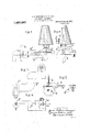
- Figs. 3 and 4 are enlarged detail side and end view of one of the cones which govern the formation of the oop bottom and of brackets carried on the upper rail.”
- Figs. 5 and 6 are respectively detail plan and front .elevation of one ofthepivoted brackets which we act on by one of the vertical stop rods. f f
- Fig. 7 is a separate detail view of one of the cams and ⁇ its cooperating spring for acting on each spindle. 1
- Fig. 8 shows in elevation, that part of the stop motion mechanism which acts on each vertical stop rod.
- Fig. 9 is a plan of Fig. 8.
- Fig. 10 shows separately one ofthe ful! crumed screw threaded rods, the movable nut, the yarn guide support or bracket and the cone contact finger which contacts with the cone.
- Another iXed horizontal shaft al is also mounted in suitable bearings in the frame and'such shaft has bossesd fixed thereon to which are secured the fixed ends of plate or other springs e the forward or yielding end of each spring c resting upon its co-acting cam c.
- the end of each spindle a rests on oneend of the said springs c each fitted with a butler strip e', and so, as the cams c rotate the spindles a are raised and lowered, while, due to the constant downward pressure of the plate springs Le any jerkiness of movef ment 1s prevented.
- the shaft?) carrying the cams c is shown as being driven indi-y without jerk orA ed to the upper rail a.
- a link belt f drives the large pulley g on the stud shaft g2 on which is a chain wheel g3 which chain wheel by al chain g4 drives a chain wheel g5 on the cam shaft Z).
- the tin roller shaft g is driven by a belt pulley gs. p
- each spindle a we employ a screw-threaded rod Zz. fulcrumed at h to an adjustable horizontal post or support 72,2, and such screw-threaded rod supports a combined sleeve i and disk i with '1 shaped flexible spring Z2 which acts as a nut in engagement with the screw threaded rod ZL.. rEach screw-threaded rod also carries a swiveling yarn guide support or bracket y' with yarn guide j and contact finger jg, the nut device z' carrying up or down the swiveling yarn guide support y', as is obvious.
- Adjustable lock nuts ,7'3 limit the extent to which the nut device z' and swiveling yarn guide support or bracket can be pressed down.
- Each contact finger 7'2 on each swiveling yarn guide support or bracket bears on a cone 7c during the formation of the cop bottom.
- Such cone 7c is conveniently carried on a spindle 7c projecting from a bracket k2 bolt- Freferably each cone 7c varies as to taper, as Figs. 3 and 4 show, so that by turning or adjusting said cone about the spindle 7Gk and securing it by means of the set screw 7a4 the form of cop bottom can be varied, that is, made steeper or less steep as required.
- the device Z0 is a truncated but incomplete cone. The taper over its face varies
- rhe part j2 is the curved extremity of the guide finger and it bears against the cone Ze.
- Each disk and nut device z' along with the yarn guide support or'bracket and contact fingery y'z is gradually elevated by reason of the rotatory motion imparted due to the disk z" contacting with the cop as the spindle is driven and the cop built-up.
- the lower end of each screwed rod Z1. fits in a slot h3 in a bracket h4 screwed to the upper rail a', and, an adjustable screw h5 limits the distance said screwed rod la, can move away from the spindle after rising clear of the influence of its cone.
- the use of the cone insures a proper solid and tapered bottom being given to the cop, and, the amount of taper on the cone governs the degree of steepness of the cop bottom, such cop bottom being fully formed when the Contact finger jz has risen sufficiently high to be freed from the influence of the cone.
- rlhe spindles a are driven indirectly from the tin roller t on the tin roller shaft g by friction, in the following simple manner, by aV band t which actuates a loose wooden or other friction sleeve Z.
- Each friction sleeve is loose on a spindle Z carried by a bracket Z2 which is pinned to a pivot spindle Z3 (see the detail view Fig. Qa).
- a boss Z* on the spindle Z and which keeps the wooden friction sleeve Z in place, is jointed by a link or rod Z5 to a lever ZG pivoted at Z7 in the upper rail a. ln this pivoted lever ZG is cut a notch ZS.
- Each spindle has a contact wherve or disk at fixed on it and the wooden friction sleeve Z is moved into and out of contact with said wherve or disk according as to whether the spindle is to be driven or arrested.
- the purpose of the notch ZS is to engage the wherve or disk a4, and immediately arrest the spindle whenever the wooden friction sleeve Z is moved out of contact, and, the lever Z6 is necessarily drawn slightly inward.
- the pivot spindle Z3 from which the wooden friction sleeve is supported is in connection with the stop motion through a bracket Z. This bracket Z9 is pinned upon the said pivot spindle Z3 (see the Fig.
- bracket Z9 is hinged and can control the wooden friction sleeve and notched lever ZG to insure the driving or arresting of the spindle a; according as the right-hand end of the bracket is pulled up on the pivot Z3, or allowed to fall.
- Each hinged bracket Z9 is acted upon by a vertical stop rod fm. which lifts up the bracket through an interposed spring fm, or otherwise, and this vertical rod is influenced by the stop mot-ion, it being obvious that when such stop rod fm. is pulled up, the wooden friction sleeve Z is pressed int-o contact with the wherve a4 on the spindle a, while, when the stop rod m moves down, said sleeve Z is taken out of contact and the notched lever ZG moved in ready to stop the spindle a by engagement of the notch Z8 with the wherve a4.
- a stop motion is fitted for each end and comprises a bracket n bolted to top rail a3 of the frame and to such bracket is pivoted at n* a drop lever n2 the verticalsto-p rod m being ⁇ jointed attrito said drop lever n2.
- This drop lever n2 normally latches by a pin n* on a notch or ledge 02 cut'on the arm 03 of a T shaped lever o pivoted at 0, and, the bracket a also carries a third lever' p, pivoted at p', which carries the. yarn guides p2 fixed on the wire p3.
- This lever f 1s also provided with a vdropper g hung rom the pin g', and said dropper g has a swell or projection@2 and can move up or down against theupright limb 04' of the T shaped lever o which limb acts as a backing or slide surface for the dropper g. f
- a rocking'shaft r supported in bearings and such shaft carries cam fingers r', that is, one for each dropper, which, as the shaft f1' rocks, moves toward and ⁇ from thedroppers (see the dotted lines, Fig. 8).
- the shaft i may Lbe rocked yin any suitable manner, and, inthe drawings an arm r2 is xed to the shaft and this arm r2 is worked by a connecting rod r3 from a bar r4 centered on the kshaft d and acted upon by a cam or eccentric on the shaft b;
- the front end of the T shaped lever 0 can itself be acted on automatically by the disk z" which may encounter a pendent device s, pivoted at s, and so the front extrmity of the lever o is elevated and the drop lever 91,2 is unlatched and falls, thus lowering the stop ⁇ rod 'm and bringing about stoppage of the spindle.
- the pendent device s adjustable, as is shown at Fig. 8, sol that the length of kcop wound can be controlled by arranging for the disk z" to encounter the lower extremity of the device s sooner or later.
- a pin a5 limits the distance the limb 03 can move back.
- the parts marked u" are hinged boards or covers which protect the front of the frame. 1 i
- Our improved frame may wind from hanks or cheeses or such like suitable Creel supply, provision being made therefor.
- a winding frame vertically movable spindles, guiding means for the spindles, a yarn guide, a coneand a threaded rod to each head, independent driving means for each winding spindle, a plate spring for each spindle, a cam acting on each plate spring, means anchoring one endr of each plate spring, each spindle resting on a plate spring and being operative there through and whereby the spindles are moved directly through the plate springs without jerk or rebound as set forth.
- a series of spindles mounted for independent axial movement, individual cams arranged to actuate the respective spindles and a flexible plate spring disposed between each spindle and yits actuating cam and being supported and arranged so as to exert pressure against the cam.
- a series of spindles mounted for independent axial movement, individual rotary cams arranged to actuate the respective spindles, and a flexible plate spring disposed ybetween each spindle and its actuating cam and being supported and arranged so as to exert pressure against the cam.
- a series of spindles mounted for independent axial movement, individual cams arranged to actuate the respective spindles, a member disposed between each spindle and its actuating cam, and resilient means for pressing each of the said members against the corresponding cam.
- a series of spindles mounted for independent axial movee sl ment, individual cams arranged to actuate the respective spindles, a member disposed between each spindle and its actuating cam, resilient means for pressing each of the said members against the corresponding cam, and means for stopping the spindles on thread breakage.
- a winding frame independently movable spindles, driving means for each spindle, and cop building mechanism for each spindle comprising a rod mounted for adjustment laterally with respect to .the spindle, a yarn guide device mounted on the said rod, means for operating the said guide device along the rod during ⁇ operation of the spindle, a forming cam mounted for adjustment about an aXis and disposed adjacent to the ysaid guide device, the said cam having an axially tapered surface which varies in taper around the periphery, and a Contact member projecting from the guide device and bearing against the peripheral surface of the cam 'so that the vlatter serves to linfluence the building of the cop bottom.
- a Winding frame independently movable spindles, driving means for each spindle, and cop building mechanism for each spindle comprising a screw-threaded rod mounted for adjustment laterally With respect to the spindle, a yarn guide device mounted on the said rod, means for operating' the-said guide device along the rod during operation of the spindle, a forming cam mounted for adjustment about an aXis and disposed adjacent to the said guide device, the said cam having an axially tapered surface which varies in taper around the periphery, a contact member projecting from the guide device and bearing against the peripheral surface of the cam so that the latter serves to influence the building of the cop bottom, and means for securing the cam in adjusted position.
Landscapes
- Engineering & Computer Science (AREA)
- Quality & Reliability (AREA)
- Spinning Or Twisting Of Yarns (AREA)
Description
J. W. MORRISON 6L TW. HOLT.
YARN WINDING MACHINERY. APPLICATION H'LED ocT.1 8, '1915.
Fi g. 1
I. W. MORRISON & T. W.HOLT. YARN wlNmNG MACHINERY.
APPLICATION HLD OCT. 18| i915- 1,237,367 Patented Aug. 21,1917.
Fig. 2.
WMV/Mmm J. W. MQRRISON 6L T. W, HOLT.
YARN WINDING MACHiNERY.
APPLICATION flLEnocT. la. |915.
Patented Aug. 21, 1917.
4 SHEETS-SHEET 3.
J. W. MORRISON & T. Wl HOLT.
YARN WINDING MACHINERY. APPLICATION FILED ocT.18. 1915.
Patented Aug. 21, 1917.
4 SHEETS-SHEET 4.
unit and independently N UNTED sTATns PATENT otros.
T WILLIAM MORRISON AND THOMAS WILLIAM I-IOLT, OF STALYBRIDGE, ENGLAND.
YARNWINDING MACHINERY.
Specification of Letters Patent.
Patented A110. 21, 191 *7.
Application filed October 18, 1915. Serial No. `56,4160.
To all ,whom t may concern.'
Be it known that we, JAMES VILLIAM MORRISON and THOMASNVILLIAM HOLT, subjects of the King of Great Britain and lre land, residing at Platt Bridge Iron Works, Stalybridge, in the county of Chester, Eng land, engineers, have invented new and usen ful Improvements rin and Connected with .Yarn-lllinding Machinery, ot which the following is a specification. y,
This invention relates to improvements in and connected with` yarn winding machinery and in particular to that class of yarn winding frame in which each spindle is a separate actuated and controlled. o
We employ plain spindles approximating to mule spindles and lthese spindles are suchqconecan be set so as to guided in two rails and are given an up and down or vertical motion to govern the length of chase or copying eitect by the action of cams cooperating each with a flat spring. o
The spindles are driven indirectly ironia tin roller through movable friction devices. The formation of each cop bottom is regulated by the use of a cone, the contact face of which preferably varies as to taper and give a steeper or less steep cop bottom as required. specting-the building, in conjunction with each cone, works a fulcrumedscrewed rod with which engages a` nut device carrying a kdisk to contact with the cop being built. The nut device acts on la support or bracket i with movable yarn guide and acontact iinger to bear against` the cone, the contact iin-y ger ultimately moving clear of the cone when. the cop bottom is fully formed.`
A stop motion is fitted whereby on vthe breakage of an end `or completion of the cop the spindle driving means are disen-- gaged andthe spindle is arrested.
We now proceedI to describe our improvements in yarn winding machinery .in detail and with reference to the attached drawings, wherein,
Figure l is an end elevation, broken in part, of a form of winding frame embodying our features of novelty, the machine being a single sided one, that is, having windingspindles along one side of the frame only. l, i
Fig. Qshows a broken frontelevation of the frame and the principal mechanism that appertains toy each spindle unit,y
F ig. 2a is a detail view.
Figs. 3 and 4 are enlarged detail side and end view of one of the cones which govern the formation of the oop bottom and of brackets carried on the upper rail."`
Figs. 5 and 6 are respectively detail plan and front .elevation of one ofthepivoted brackets which we act on by one of the vertical stop rods. f f
Fig. 7 is a separate detail view of one of the cams and `its cooperating spring for acting on each spindle. 1
Fig. 8 shows in elevation, that part of the stop motion mechanism which acts on each vertical stop rod.
Fig. 9 is a plan of Fig. 8.
Fig. 10 shows separately one ofthe ful! crumed screw threaded rods, the movable nut, the yarn guide support or bracket and the cone contact finger which contacts with the cone. c
Fig. l1 is a detail planet the yarn guide support or bracket, &c.
We make use of plain spindles a which are verysimilar to mule s1 indles andthese are an easy slidable iit in bearingsfformed in two rails a', a2 so as to be free to move up and down. It is an important feature of our invention to impart easyl vertical movement oi" the spindles a rebound. Below the line of spindles a we iix a rotating horizontal shaft o, and this shaft o carries heart shaped or other cams such as c there being one cam inrespect of each spindle a. Another iXed horizontal shaft al is also mounted in suitable bearings in the frame and'such shaft has bossesd fixed thereon to which are secured the fixed ends of plate or other springs e the forward or yielding end of each spring c resting upon its co-acting cam c. Ars shown, the end of each spindle a rests on oneend of the said springs c each fitted with a butler strip e', and so, as the cams c rotate the spindles a are raised and lowered, while, due to the constant downward pressure of the plate springs Le any jerkiness of movef ment 1s prevented. The shaft?) carrying the cams c is shown as being driven indi-y without jerk orA ed to the upper rail a.
cam and thus to sensitively and gradually affect the spindle. In the arrangement illustrated, a link belt f drives the large pulley g on the stud shaft g2 on which is a chain wheel g3 which chain wheel by al chain g4 drives a chain wheel g5 on the cam shaft Z). The tin roller shaft g is driven by a belt pulley gs. p
In connection with each spindle a, we employ a screw-threaded rod Zz. fulcrumed at h to an adjustable horizontal post or support 72,2, and such screw-threaded rod supports a combined sleeve i and disk i with '1 shaped flexible spring Z2 which acts as a nut in engagement with the screw threaded rod ZL.. rEach screw-threaded rod also carries a swiveling yarn guide support or bracket y' with yarn guide j and contact finger jg, the nut device z' carrying up or down the swiveling yarn guide support y', as is obvious. Adjustable lock nuts ,7'3 limit the extent to which the nut device z' and swiveling yarn guide support or bracket can be pressed down. Each contact finger 7'2 on each swiveling yarn guide support or bracket bears on a cone 7c during the formation of the cop bottom. Such cone 7c is conveniently carried on a spindle 7c projecting from a bracket k2 bolt- Freferably each cone 7c varies as to taper, as Figs. 3 and 4 show, so that by turning or adjusting said cone about the spindle 7Gk and securing it by means of the set screw 7a4 the form of cop bottom can be varied, that is, made steeper or less steep as required.
The device Z0 is a truncated but incomplete cone. The taper over its face varies,
` that is, the taper varies as to steepness,
at one part such taper may be greater than at another. By adjusting the cone lc about the spindle lc a variation in taper is provided for, that is, the "inclination for the guide finger y' to press against may be varied. The drawings show this very clearly in Fig` l. The front taper (left-hand side) in Fig. l is much more pronounced than the rear face (right hand side) Fig. 1.
rhe part j2 is the curved extremity of the guide finger and it bears against the cone Ze.
As the guide finger rises'up the cone, it is y obvious that the yarn guide end y" can recede from the spindle center, and it does slowly recede until such time as the cop bottom is fully formed when the screwed spindle cannot fall away farther because of the screwed adjusting stop h5. Cones for use in connection 'with the formation of cop bottoms are well known. The cone 7c is obviously adjustable, about the part lo', to get the taper desired the cone being fixed by the pinching screw 704.
Each disk and nut device z' along with the yarn guide support or'bracket and contact fingery y'z is gradually elevated by reason of the rotatory motion imparted due to the disk z" contacting with the cop as the spindle is driven and the cop built-up. The lower end of each screwed rod Z1. fits in a slot h3 in a bracket h4 screwed to the upper rail a', and, an adjustable screw h5 limits the distance said screwed rod la, can move away from the spindle after rising clear of the influence of its cone.
As will be understood, the use of the cone insures a proper solid and tapered bottom being given to the cop, and, the amount of taper on the cone governs the degree of steepness of the cop bottom, such cop bottom being fully formed when the Contact finger jz has risen sufficiently high to be freed from the influence of the cone.
rlhe spindles a are driven indirectly from the tin roller t on the tin roller shaft g by friction, in the following simple manner, by aV band t which actuates a loose wooden or other friction sleeve Z. Each friction sleeve is loose on a spindle Z carried by a bracket Z2 which is pinned to a pivot spindle Z3 (see the detail view Fig. Qa). A boss Z* on the spindle Z and which keeps the wooden friction sleeve Z in place, is jointed by a link or rod Z5 to a lever ZG pivoted at Z7 in the upper rail a. ln this pivoted lever ZG is cut a notch ZS. Each spindle has a contact wherve or disk at fixed on it and the wooden friction sleeve Z is moved into and out of contact with said wherve or disk according as to whether the spindle is to be driven or arrested. The purpose of the notch ZS is to engage the wherve or disk a4, and immediately arrest the spindle whenever the wooden friction sleeve Z is moved out of contact, and, the lever Z6 is necessarily drawn slightly inward. The pivot spindle Z3 from which the wooden friction sleeve is supported is in connection with the stop motion through a bracket Z. This bracket Z9 is pinned upon the said pivot spindle Z3 (see the Fig. 5) and so the said bracket Z9 is hinged and can control the wooden friction sleeve and notched lever ZG to insure the driving or arresting of the spindle a; according as the right-hand end of the bracket is pulled up on the pivot Z3, or allowed to fall.
Each hinged bracket Z9 is acted upon by a vertical stop rod fm. which lifts up the bracket through an interposed spring fm, or otherwise, and this vertical rod is influenced by the stop mot-ion, it being obvious that when such stop rod fm. is pulled up, the wooden friction sleeve Z is pressed int-o contact with the wherve a4 on the spindle a, while, when the stop rod m moves down, said sleeve Z is taken out of contact and the notched lever ZG moved in ready to stop the spindle a by engagement of the notch Z8 with the wherve a4.
A stop motion is fitted for each end and comprises a bracket n bolted to top rail a3 of the frame and to such bracket is pivoted at n* a drop lever n2 the verticalsto-p rod m being `jointed attrito said drop lever n2. This drop lever n2 normally latches by a pin n* on a notch or ledge 02 cut'on the arm 03 of a T shaped lever o pivoted at 0, and, the bracket a also carries a third lever' p, pivoted at p', which carries the. yarn guides p2 fixed on the wire p3. This lever f 1s also provided with a vdropper g hung rom the pin g', and said dropper g has a swell or projection@2 and can move up or down against theupright limb 04' of the T shaped lever o which limb acts as a backing or slide surface for the dropper g. f
In juxta-position to the rank of droppers 2 is a rocking'shaft r supported in bearings and such shaft carries cam fingers r', that is, one for each dropper, which, as the shaft f1' rocks, moves toward and `from thedroppers (see the dotted lines, Fig. 8). The shaft i may Lbe rocked yin any suitable manner, and, inthe drawings an arm r2 is xed to the shaft and this arm r2 is worked by a connecting rod r3 from a bar r4 centered on the kshaft d and acted upon by a cam or eccentric on the shaft b;
So long as the yarn passing down to the spindle over the flexible yarn guides p2, p3 or the like, remains unbroken, the yarn guide lever p is sustained (see the full lines, Fig. 8), and the swell on the dropper is kept clear of its particular cam finger on the rocking shaft r, and, conditions remain normal because the lever n2 holds up the vertical stop rod m. On breakage of an end, the dropper g falls and presents the swell 'q2 in the path ofthe cam .finger r',
\ which," acting thereon, influences the T lever o and so unships or unlatches the drop lever n? and allows the vertical stop rod m to fall or move down. Thus ,the right-hand end of the bracket Z9 is nok longer sustained and the Wooden driving sleeve Z is taken out of contact with the spindle wherve and the notched lever ZG arrests and holds the spindle After piecing-up, the yarn again holds down the front end o-f the yarn guide lever and so holds up the dropper with lits swell Q2, and to commence winding, all the attendant requires to `do is, to `latch the drop lever n2 on the notch 02 in the T shaped lever o whereupon the driving of the spindle is again taken up.
lhen the cop is fully wound, the front end of the T shaped lever 0 can itself be acted on automatically by the disk z" which may encounter a pendent device s, pivoted at s, and so the front extrmity of the lever o is elevated and the drop lever 91,2 is unlatched and falls, thus lowering the stop `rod 'm and bringing about stoppage of the spindle. We prefer to make the pendent device s adjustable, as is shown at Fig. 8, sol that the length of kcop wound can be controlled by arranging for the disk z" to encounter the lower extremity of the device s sooner or later. A pin a5 limits the distance the limb 03 can move back.
We may make framesto wind on both sides as is apparent. f
.If desired we can arrange to wind on bare spindles by providing cams which give a fairly quick drop to 'allow of a binding thread being laid.
The parts marked u" are hinged boards or covers which protect the front of the frame. 1 i
Our improved frame may wind from hanks or cheeses or such like suitable Creel supply, provision being made therefor. f
le declare that what we claim ist l. In a winding frame, vertically movable spindles, separate driving devices for each spindle, means to drive same, cams to move said spindles vertically, and flexible plate springs, anchoring means for one end of each spring, the spindles resting on the plate springs, said springs pressing on the cams, said cams operatingy the spindle through the plate springs, and whereby said spindles are moved up and down without jerk or rebound,
2. A winding frame, vertically movable spindles, guiding means for the spindles, a yarn guide, a coneand a threaded rod to each head, independent driving means for each winding spindle, a plate spring for each spindle, a cam acting on each plate spring, means anchoring one endr of each plate spring, each spindle resting on a plate spring and being operative there through and whereby the spindles are moved directly through the plate springs without jerk or rebound as set forth.
8. In a winding frame, a series of spindles mounted for independent axial movement, individual cams arranged to actuate the respective spindles and a flexible plate spring disposed between each spindle and yits actuating cam and being supported and arranged so as to exert pressure against the cam. j
4l. In a winding frame, a series of spindles mounted for independent axial movement, individual rotary cams arranged to actuate the respective spindles, and a flexible plate spring disposed ybetween each spindle and its actuating cam and being supported and arranged so as to exert pressure against the cam.
5. Ina winding frame, a series of spindles mounted for independent axial movement, individual cams arranged to actuate the respective spindles, a member disposed between each spindle and its actuating cam, and resilient means for pressing each of the said members against the corresponding cam. j
6. In a winding frame, a series of spindles mounted for independent axial movee sl ment, individual cams arranged to actuate the respective spindles, a member disposed between each spindle and its actuating cam, resilient means for pressing each of the said members against the corresponding cam, and means for stopping the spindles on thread breakage.
7. In a winding frame, independently movable spindles, driving means for each spindle, and cop building mechanism for each spindle comprising a rod mounted for adjustment laterally with respect to .the spindle, a yarn guide device mounted on the said rod, means for operating the said guide device along the rod during` operation of the spindle, a forming cam mounted for adjustment about an aXis and disposed adjacent to the ysaid guide device, the said cam having an axially tapered surface which varies in taper around the periphery, and a Contact member projecting from the guide device and bearing against the peripheral surface of the cam 'so that the vlatter serves to linfluence the building of the cop bottom. 8. In a Winding frame, independently movable spindles, driving means for each spindle, and cop building mechanism for each spindle comprising a screw-threaded rod mounted for adjustment laterally With respect to the spindle, a yarn guide device mounted on the said rod, means for operating' the-said guide device along the rod during operation of the spindle, a forming cam mounted for adjustment about an aXis and disposed adjacent to the said guide device, the said cam having an axially tapered surface which varies in taper around the periphery, a contact member projecting from the guide device and bearing against the peripheral surface of the cam so that the latter serves to influence the building of the cop bottom, and means for securing the cam in adjusted position.
' In testimony whereof we have signed our names to this specification in the presence of tivo subscribing Witnesses.
J AMES WILLIAM MORRISON. THOMAS WILLIAM I-IOL'I.
Witnesses RICHARD WEBSTER IBBERsoN, ALFRED STUART YATES.
Copies of this patent may be obtained for five cents each, by addressing the Commissioner of Patents, Washington, D. C.
Priority Applications (1)
| Application Number | Priority Date | Filing Date | Title |
|---|---|---|---|
| US5646015A US1237367A (en) | 1915-10-18 | 1915-10-18 | Yarn-winding machinery. |
Applications Claiming Priority (1)
| Application Number | Priority Date | Filing Date | Title |
|---|---|---|---|
| US5646015A US1237367A (en) | 1915-10-18 | 1915-10-18 | Yarn-winding machinery. |
Publications (1)
| Publication Number | Publication Date |
|---|---|
| US1237367A true US1237367A (en) | 1917-08-21 |
Family
ID=3305186
Family Applications (1)
| Application Number | Title | Priority Date | Filing Date |
|---|---|---|---|
| US5646015A Expired - Lifetime US1237367A (en) | 1915-10-18 | 1915-10-18 | Yarn-winding machinery. |
Country Status (1)
| Country | Link |
|---|---|
| US (1) | US1237367A (en) |
-
1915
- 1915-10-18 US US5646015A patent/US1237367A/en not_active Expired - Lifetime
Similar Documents
| Publication | Publication Date | Title |
|---|---|---|
| US1237367A (en) | Yarn-winding machinery. | |
| US887280A (en) | Sliver-evening mechanism for drawing-frames. | |
| US116677A (en) | Improvement in stop-motions and creel-stands for knitting-machines | |
| US731272A (en) | Combined spinning and twisting machine. | |
| US392172A (en) | Evening mechanism for railway-heads | |
| US568621A (en) | Tension device for grain-binding machines | |
| US1022004A (en) | Cross-winding machine. | |
| US134567A (en) | Improvement in self-acting spinning-jacks | |
| US408874A (en) | Stop mechanism for doubling-machines | |
| US1205565A (en) | Winding-machine. | |
| US610162A (en) | Thread-spooling or quilling machine | |
| US1099772A (en) | Stop-motion. | |
| US49860A (en) | Improvement in self-acting mules | |
| US534992A (en) | Railway-head | |
| US398359A (en) | Machine for throwing silk | |
| US1228410A (en) | Creel. | |
| US682878A (en) | Doubling-frame. | |
| US50230A (en) | Improvement in spinning-jacks | |
| US303209A (en) | stop motion mechanism foe twisting and winding machines | |
| US364785A (en) | Machine forthrowing silk | |
| US473417A (en) | The norois peters co | |
| US1290447A (en) | Winding-machine. | |
| US56829A (en) | Improvement in self-acting mules | |
| US355678A (en) | Tension device for grain-binders | |
| US240957A (en) | peters |