US1237349A - Demountable rim. - Google Patents
Demountable rim. Download PDFInfo
- Publication number
- US1237349A US1237349A US4099215A US4099215A US1237349A US 1237349 A US1237349 A US 1237349A US 4099215 A US4099215 A US 4099215A US 4099215 A US4099215 A US 4099215A US 1237349 A US1237349 A US 1237349A
- Authority
- US
- United States
- Prior art keywords
- rim
- tire
- felly
- band
- studs
- Prior art date
- Legal status (The legal status is an assumption and is not a legal conclusion. Google has not performed a legal analysis and makes no representation as to the accuracy of the status listed.)
- Expired - Lifetime
Links
- 230000006698 induction Effects 0.000 description 3
- 239000011324 bead Substances 0.000 description 2
- 230000002093 peripheral effect Effects 0.000 description 1
- 238000000926 separation method Methods 0.000 description 1
Images

Classifications
-
- B—PERFORMING OPERATIONS; TRANSPORTING
- B60—VEHICLES IN GENERAL
- B60B—VEHICLE WHEELS; CASTORS; AXLES FOR WHEELS OR CASTORS; INCREASING WHEEL ADHESION
- B60B23/00—Attaching rim to wheel body
- B60B23/06—Attaching rim to wheel body by screws, bolts, pins, or clips
- B60B23/10—Attaching rim to wheel body by screws, bolts, pins, or clips arranged axially
Definitions
- This invention relates to improvements in vehicle wheels and more particularly to a novel demountable rim and means for sei curing the same in place upon the felly band of the wheel.
- the rim embodying the present invention is in the form of an open annulus and the invention aims to provide novel means forfirmly and securely connecting the ends of the rim and for holding these ends against separation when the rim is in'place upon the felly band.
- Another aim of the invention is to provide novel means for accommodating the induction tube for the inner tube of the tire.
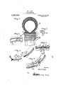
- Figure ⁇ 1 is a side elevation of a wheel equipped with the rim embodying the present invention.
- FIG. 1 is a vertical transverse sectional view through the device.
- Fig. 3 is a perspective View ofthe meetin ends of the demountable tire rim in position about to be connected.
- Fig. 7 is a perspective view ofone of the i; i clamps for holding the tire ⁇ 'rim in P1206 upon the felly ban Corresponding and like parts are referred to in the following description and indi- Specificationof Letters Patent. Patented Aug, 2L jfgjl', Application filed muy zo, 191.5. serial No. 40,992.
- the numeral 1 indicates -the'felly of thel wheel and this felly is peripherally of frusto-conical form or, in other words, is eXteriorly tapered toward one side of the wheel as indicated at 2.
- the felly band of the wheel ⁇ is indicated by the numeral 3 and the body portion thereof is of frustoeconical form [and adapted to be fitted snugly to the peripheral surface of the felly1 ⁇ in the manner clearlyshown in Fig. 2 of the drawings.
- the felly band 3 is provided with a iange 4 against which the tire rim is to be disposed and held in a manner to be presently explained.
- the band 3 is provided with an inwardly projecting flange 5 which, when the band is in place upon the 4felly 1, restsagainst one side face of the said felly, as clearly shown in the said Fig. 2.
- Interiorly t-he rim 7 is of frusto-conical form and the rim is adapted to be fitted to the-felly band with its inner surface ksnugly fitting the outer surface of the said band. In that", ⁇ form of the invention shown in Fig.
- Vthe rim at one end is reduced in thickness, as indicated at 11 to form a transverse shoulder 12 and studs 13 are provided upon the inner surface of the reduced portion 11, preferably .in alinement circumferentially of the rim.
- the opposite end of the rim is also reduced in thickness, as indicatedat 14, and provided with openings 15 designed to receive the studs 13 when the portions 11 and 14 of the said ends of the rim are brought together in overlapped relation in the mannerclearly shown in Fig. 5 of they drawings'.
- the induction tube for the inner tube of the tire may be ⁇ a :commodated,v the rimA formed at that substantially at the line end at which the portion 14 is located, and of juncture of this portion with the said end of the rim with an opening 16 designed to register with a notch or recess 17 formed in theextremity of the reduced portion 11 of the opposite end of the rim when the two ends are assembled, as above stated, the said induction tube for the inner ytube of the tire being fitted through the opening 16 and received within this opening and within the concavity of the recess 17.
- Each of the clamps above mentioned comprises a body portion 18 formed with an opening 19 and at one end with a li 20 projecting from one face thereof and at its other end with a stud 21 also projecting from the said face. Any desired number of these clamps may be employed and they are disposed in the position shown in Fig.
- Bolts e 22 are iitted through the iellyl and through openings 23 formed in the .iange 5 for their reception and through the openings 9 in the clamps. and nuts 24 are threaded onto the ends oi the bolts and bear against the said clamps and serve to bind the same against the tire rim.
- the engagement of the studs 21 in the openings 6 serves to prevent rotation of the clamps to position out of engagement with the tire rim but that, when it is desired to remove the rim, the nuts 24 may be turned back until the studs 21 may be disengaged from within the openings 6,where upon the clamps may be rotated upon their respective bolts so as to provide clearance for the said tire rim.
- one end of the rim being also reduced in thickness, as indi-- cated in Fig. 1, and itsl extremity being designed to abut against the shoulder 26 in the same manner as in the instance of the portion 14 in the shoulder 12 in the form previously described.
- one end of the rim is provided with an opening 32 and the other end with a notch 33, correspending respectively to the opening 16 and notch 17 5 and designed to accommodate the retraction or inflation tube for the inner tub# of the tire.
- the studs 13 are formed of such length that they will project not only through the openings 13 but will also engage at their free ends in openings 13 formed in said felly band.
- the said projecting first mentioned end of the rim being provided with sockets to receive the said studs.
Landscapes
- Engineering & Computer Science (AREA)
- Mechanical Engineering (AREA)
- Tires In General (AREA)
Description
W. C. LONG.l oEMouNTALE mM. APPucAUoN man xuLY M1915( ,Patented Aug. 21, 1917.
2 SHEETS-SHEET l.
` W. C. LONG... nEMouNTAaLE nm. PPLICATION FILED JULY 20.1915.
1,237,349'. Q rammed Aug. 21,1917,
' 2 suns-snm 2( n y I UNITED STATES ,PATENT onnion.
- WALTER C. LONG, 0F L'OUDONVILLE, OHIO.
DEMOUNTABLE RIM.
To all whom it may concern."
Be it known that "I, WALTER C. LONG, a
citizen of the United States, residing at tion.
This invention relates to improvements in vehicle wheels and more particularly to a novel demountable rim and means for sei curing the same in place upon the felly band of the wheel.
` It is one aim of the invention to provide a demountable rim which may be readil'y and quickly manipulated so as to permit rlof its being disengaged from the -tire easing-when "it is desired to remove the said casing for any purpose,` and which will, nevertheless, be 'so constructed as to securely hold the casing when in place upon the wheel and will not be liable to lbecome accidentally displaced.
The rim embodying the present invention is in the form of an open annulus and the invention aims to provide novel means forfirmly and securely connecting the ends of the rim and for holding these ends against separation when the rim is in'place upon the felly band. l y
Another aim of the invention is to provide novel means for accommodating the induction tube for the inner tube of the tire.
In the accompanying drawings:v
Figure `1 is a side elevation of a wheel equipped with the rim embodying the present invention. l
'Fig 2 is a vertical transverse sectional view through the device.
Fig. 3 is a perspective View ofthe meetin ends of the demountable tire rim in position about to be connected.
. removed from the felly of the wheel.
Fig. 7 is a perspective view ofone of the i; i clamps for holding the tire `'rim in P1206 upon the felly ban Corresponding and like parts are referred to in the following description and indi- Specificationof Letters Patent. Patented Aug, 2L jfgjl', Application filed muy zo, 191.5. serial No. 40,992.
catedin all the views of the accompanying drawings` by the same reference characters. In the drawings, the numeral 1 indicates -the'felly of thel wheel and this felly is peripherally of frusto-conical form or, in other words, is eXteriorly tapered toward one side of the wheel as indicated at 2. The felly band of the wheel `is indicated by the numeral 3 and the body portion thereof is of frustoeconical form [and adapted to be fitted snugly to the peripheral surface of the felly1`in the manner clearlyshown in Fig. 2 of the drawings. At one Side of the wheel the felly band 3 is provided with a iange 4 against which the tire rim is to be disposed and held in a manner to be presently explained. At its opposite side the band 3is provided with an inwardly projecting flange 5 which, when the band is in place upon the 4felly 1, restsagainst one side face of the said felly, as clearly shown in the said Fig. 2. For a purpose also to be pres- 4provided at its opposite sides with anges 8 of the ordinary form to engage and grip the beads 9 of the tire casing, which casing is indicated by the numeral 10. Interiorly t-he rim 7 is of frusto-conical form and the rim is adapted to be fitted to the-felly band with its inner surface ksnugly fitting the outer surface of the said band. In that",` form of the invention shown in Fig. 3 of the s drawings, Vthe rim at one end is reduced in thickness, as indicated at 11 to form a transverse shoulder 12 and studs 13 are provided upon the inner surface of the reduced portion 11, preferably .in alinement circumferentially of the rim. The opposite end of the rim is also reduced in thickness, as indicatedat 14, and provided with openings 15 designed to receive the studs 13 when the portions 11 and 14 of the said ends of the rim are brought together in overlapped relation in the mannerclearly shown in Fig. 5 of they drawings'. When the ends of the rim'are thus connected the' end of the por-v tion 14 will abut against the shoulder 12 and the studs- 13 will fit snugly within the openings 15. In order that the induction tube for the inner tube of the tire may be `a :commodated,v the rimA formed at that substantially at the line end at which the portion 14 is located, and of juncture of this portion with the said end of the rim with an opening 16 designed to register with a notch or recess 17 formed in theextremity of the reduced portion 11 of the opposite end of the rim when the two ends are assembled, as above stated, the said induction tube for the inner ytube of the tire being fitted through the opening 16 and received within this opening and within the concavity of the recess 17. V
At this point'it will be understood that when the rim is to be applied to the tire casing, it is contracted` until its ends pro-' ject past each other and the rim is then Vdisposed lwithin the tire casing and permitted to expand by its resiliency, the beads 9 of the casing being at the same time engaged with the flanges 8. As the rim eX,- pands, its reduced end portions will assume an overlapped relation and the studs 13 will engage the openings 15, thereby connecting the said ends in the y.ma-nner clearly .shown in Fig. 5. The rim may then be readily fitted onto the elly band 8 and secured in place by means of a suitable number lof clamps of the structure shown in Fig. 7 of the drawings.
Each of the clamps above mentioned comprises a body portion 18 formed with an opening 19 and at one end with a li 20 projecting from one face thereof and at its other end with a stud 21 also projecting from the said face. Any desired number of these clamps may be employed and they are disposed in the position shown in Fig.
2 of the drawings, or, in other words,
against the flange 5 of the felly band with the studs 21 projecting into the openings 6 in the said band and with the lips 20 kengaging against the adjacent side of the tire rim, as shown in the said figure. Bolts e 22 are iitted through the iellyl and through openings 23 formed in the .iange 5 for their reception and through the openings 9 in the clamps. and nuts 24 are threaded onto the ends oi the bolts and bear against the said clamps and serve to bind the same against the tire rim. It will be understood that the engagement of the studs 21 in the openings 6 serves to prevent rotation of the clamps to position out of engagement with the tire rim but that, when it is desired to remove the rim, the nuts 24 may be turned back until the studs 21 may be disengaged from within the openings 6,where upon the clamps may be rotated upon their respective bolts so as to provide clearance for the said tire rim.
In that form of the invention shown in Fig. 4 of the drawings, one end of the rim being also reduced in thickness, as indi-- cated in Fig. 1, and itsl extremity being designed to abut against the shoulder 26 in the same manner as in the instance of the portion 14 in the shoulder 12 in the form previously described. As in the previously described form of the invention, one end of the rim is provided with an opening 32 and the other end with a notch 33, correspending respectively to the opening 16 and notch 17 5 and designed to accommodate the retraction or inflation tube for the inner tub# of the tire.
In order that the rim may be prevented from creeping about the felly band 3 of the wh/eel, the studs 13 are formed of such length that they will project not only through the openings 13 but will also engage at their free ends in openings 13 formed in said felly band. In that form of i-lie invention shown in Fig. 4 the result lthe lianges at one vend of the body terminating short of said end and the body at its other end being recessed at its under side to form a shoulder spaced inwardly fromits said end, the iirst mentioned end of the body being arranged to overlap the projecting portion at the other end of the body, in the mounted position of the tire, with the ends of the iiangcs abutting and with the projecting rst mentioned end of the rim abutting against the said shoulder at the other end of the rim and spaced studs arranged in circumferential alinement upon the inner face of the projecting portion at the second mentioned end of the rim. the said projecting first mentioned end of the rim being provided with sockets to receive the said studs.
In testimony whereof I affix my signature.
WALTER o. LONG. [ne]
Priority Applications (1)
| Application Number | Priority Date | Filing Date | Title |
|---|---|---|---|
| US4099215A US1237349A (en) | 1915-07-20 | 1915-07-20 | Demountable rim. |
Applications Claiming Priority (1)
| Application Number | Priority Date | Filing Date | Title |
|---|---|---|---|
| US4099215A US1237349A (en) | 1915-07-20 | 1915-07-20 | Demountable rim. |
Publications (1)
| Publication Number | Publication Date |
|---|---|
| US1237349A true US1237349A (en) | 1917-08-21 |
Family
ID=3305168
Family Applications (1)
| Application Number | Title | Priority Date | Filing Date |
|---|---|---|---|
| US4099215A Expired - Lifetime US1237349A (en) | 1915-07-20 | 1915-07-20 | Demountable rim. |
Country Status (1)
| Country | Link |
|---|---|
| US (1) | US1237349A (en) |
-
1915
- 1915-07-20 US US4099215A patent/US1237349A/en not_active Expired - Lifetime
Similar Documents
| Publication | Publication Date | Title |
|---|---|---|
| US2614603A (en) | Adapter for truck wheel rims | |
| US1237349A (en) | Demountable rim. | |
| US1515940A (en) | Wheel for automobiles, etc | |
| US1235360A (en) | Tire-rim. | |
| US1342622A (en) | Vehicle-wheel | |
| US1139896A (en) | Vehicle-wheel. | |
| US1203996A (en) | Sectional rim. | |
| US1274237A (en) | Tire and fastening means therefor. | |
| US1166817A (en) | Wheel. | |
| US1311126A (en) | kelsey | |
| US1390141A (en) | Automobile-wheel rim | |
| US1646677A (en) | Demountable rim for tires | |
| US1001886A (en) | Demountable rim. | |
| US940602A (en) | Vehicle-wheel rim. | |
| US1193781A (en) | heinig | |
| US1286206A (en) | Wheel-rim. | |
| US1395362A (en) | Vehicle-wheel | |
| US960983A (en) | Separable rim for vehicle-wheels. | |
| US1093234A (en) | Felly-band and rim for wheels. | |
| US1849464A (en) | Demountable wheel rim assembly | |
| US1095349A (en) | Demountable tire-rim. | |
| US1514864A (en) | Rim for vehicle tires and wheels | |
| US1228557A (en) | Wheel. | |
| US1479095A (en) | Clincher rim | |
| US1525862A (en) | Demountable rim |