US1237348A - Paper-feeding machine. - Google Patents
Paper-feeding machine. Download PDFInfo
- Publication number
- US1237348A US1237348A US11499116A US11499116A US1237348A US 1237348 A US1237348 A US 1237348A US 11499116 A US11499116 A US 11499116A US 11499116 A US11499116 A US 11499116A US 1237348 A US1237348 A US 1237348A
- Authority
- US
- United States
- Prior art keywords
- sheet
- instrumentality
- feeding
- pressure
- instrumentalities
- Prior art date
- Legal status (The legal status is an assumption and is not a legal conclusion. Google has not performed a legal analysis and makes no representation as to the accuracy of the status listed.)
- Expired - Lifetime
Links
- 230000005484 gravity Effects 0.000 description 3
- 238000003825 pressing Methods 0.000 description 3
- 230000001276 controlling effect Effects 0.000 description 2
- 230000000737 periodic effect Effects 0.000 description 2
- 230000002093 peripheral effect Effects 0.000 description 2
- 230000001105 regulatory effect Effects 0.000 description 2
- 230000000903 blocking effect Effects 0.000 description 1
- 238000010276 construction Methods 0.000 description 1
- 230000002079 cooperative effect Effects 0.000 description 1
- 238000006073 displacement reaction Methods 0.000 description 1
- 238000007689 inspection Methods 0.000 description 1
- 230000003534 oscillatory effect Effects 0.000 description 1
- 230000000717 retained effect Effects 0.000 description 1
- 230000000630 rising effect Effects 0.000 description 1
- 230000002459 sustained effect Effects 0.000 description 1
Images


Classifications
-
- B—PERFORMING OPERATIONS; TRANSPORTING
- B65—CONVEYING; PACKING; STORING; HANDLING THIN OR FILAMENTARY MATERIAL
- B65H—HANDLING THIN OR FILAMENTARY MATERIAL, e.g. SHEETS, WEBS, CABLES
- B65H3/00—Separating articles from piles
- B65H3/02—Separating articles from piles using friction forces between articles and separator
- B65H3/06—Rollers or like rotary separators
- B65H3/0638—Construction of the rollers or like rotary separators
- B65H3/0646—Wave generation rollers, i.e. combing wheels
Definitions
- PAPER FEEDING MACHINE APPLKCUATION FiLEB AUGAS. 1916.
- n we wroz UNITED STATES PATENT OFFICE.
- the primary object of this invention is to provide improved means for applying additional pressure to the combing instrumentalities and in chang ing the relative pressure on said sheet-feedin-g instrumentalities for straightening the sheet.
- one of the objects of my invention is to provide an improved construction, combination and arrangement of parts 1n a devlce of this character in virtue of which the mechanism for applying additional pressure to laterally spaced combing wheels, equalizes the additional pressure between said combing wheels as long as they are both activebut automatically applies the entire additional pressure to one of said combing wheels as soon as the other combing wheel is raised from the pile under the actiongof sheet-controlled means.
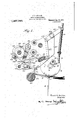
- Figure 1 is a side elevation of a preferred embodiment of my invention under normal working conditions, parts being shown i1? section;
- Fig. 2 is a front elevation of th same
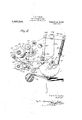
- Fig. 3 is. a rear elevation of the same
- Fig. 4 is a view' similar to Fig. 1 showing parts thereof in different positions;
- Fig. 5 is a view similar to Figs l and/l showing some ofthe parts in changed posis tions to which they have been moved from the positions shown in Fig. 4.
- a pile of sheets 1 is suitably mounted to have the positions ofthe forward.edges of the different sheets determined by vertical bars or guides 52, having forwardly deflected slightly upturned portions 3 over which saidzsheets are fed one by one by means of laterally spaced bombing wheels 4 which .arejournaled on shafts 5 carried in the outer ends of lever arms 6.
- Two of the lever arms 6 are shown in Fig. 3.
- Each lever arm 6 is provided with a hub portion 7 keyed. to separately movable sleeves 8 which are journaled on a common shaft,9.
- the sleeves 8 are independently oscillated under the control of sheet actuated means (not shown) which determines the period of comb for the purpose of straightening a sheet.
- sheet actuated means (not shown) which determines the period of comb for the purpose of straightening a sheet.
- said combing-wheels are usually raised at'peri- .Odic intervals independently of said sheetactuated means, the latter means ordinarily becoming efi'ectivef before the periodically operated. means. Not infrequently, however, it happens that the full period of-comb is notsuflicient to advance the top sheet of a pile into position to-be fed off.
- Patent No. 1,165,521 granted to' me on December 28th, 1915, I have described and claimed means for applying additional pressure to a combing wheel for increasing the amount of feed that is givento the top sheet of a pile.
- each of the shafts 5 projects inwardly from the inside lever arm 6 which helps'to support it.
- Rigidly secured to each of the shafts 5 is a bracket 10.
- onewend of a rod 11 is journaled by meansof a pin 12.
- the other end of rod 11 is slidably mounted in a cylindrical block 13 having reduced ends 14 journaled in the left hand bracket 10.
- An arm 15 which is mounted on the rod 11 intermediately of the br'ackets l interposed a spring 19 which imparts a yieldable additional pressure to the combing wheels 4, 4 under the action of mechanism to be presently described.
- the cylindrical block 18 is provided with a stud 20 which is rotatably mounted in the boss 21 on the upper end of a lever 22, being retained therein by a nut 23.
- Lever 22 is journaled on a stud 24 threaded into a bracket support 25.
- the otherarm of lever 22 is pivotally connected at 26 with the upper end of a connecting rod 27, the lower endof said rod being pivotally connected at 28 to one arm of a lever 29 which is pivoted at 30 on the bracket support 25.
- the other arm of lever 29 carries a pin 31 which is adapted under certain predetermined conditions to be engaged by a hook 32 on a detachable link 33.
- the link 33 is pivotally connected at 34 to the depending end of a cam lever 35, which is journaled on a stud 36 carried by the bracket support 25.
- the cam lever carries a pin or stud 37 upon which is journaled a cam roller 38 which travels over the peripheral surface of a cam 39 keyed to a cam shaft 40.
- the cam shaft 40v rotates continuously and thereby imparts a periodic reciprocation to the detachable link 33.
- Another cam 41 is for the most part circular but contains a peripheral recess 42, which under certain predetermined conditions permits a cam roller 43 carried by a cam lever 44, to move inwardly toward the cam shaft 40.
- Cam levers 35 and 44 are provided with yieldable means (not shown) for drawing said levers toward their respective cams.
- Cam lever 44 is oscillatable preferably about the axes of a stud 45, the hub 46 of said cam lever being provided with. a downwardly and rearwardlyproj ecting arm47 upon which a dog or finger 48 is
- the rear and lower end of the arm 47 carries a pendulum 51 which is adapted to swing abouta pivot 52 when acted upon by a sheet in the manner to be presently described.
- the forwardly presented portion of the guide bar 2 is provided with a recess 53 which is suitably arranged to accommodate the pendulum 51 when a sheet is not present to prevent said pendulum assuming a vertical position under the action of gravity.
- a plate or table 54 which is adapted to preventthe downward displacement of the pendulum 51 whenever said pendulum is displaced by a sheet when the forward edge of said sheet reaches a point within a redetermined distance of the drop rollers not shown).
- the detachable link 33 is pendulum 51 rests upon the plate or-table 54 during the time that the cam roller 43 is passing over the recess 42 in cam 41 after which said cam 41 by again coming into engagement with the cam roller 43, lifts pendulum 51 slightly away from plate or table 54 and permits the sheet to throw said pendulum into dotted line position shown in Fig. 1. This is what happens during the normal operation of the machine when the cooperative action of laterally spaced combing wheels straightens the tdp sheet while bringing its forward edge up to within a certain predetermined distance of-the drop rollers.
- the spring 50 acts to hold the dog or finger 48 against a stop 55 on the hub 46 of cam lever 44, thereby preventing the detachable link 33 from dropping into engagement with the pin 31 during the next rearward movement of link 33.
- the spring 50 acts to hold the dog or finger 48 against a stop 55 on the hub 46 of cam lever 44, thereby preventing the detachable link 33 from dropping into engagement with the pin 31 during the next rearward movement of link 33.
- the sheets do not feed as freely as necessary, for a proper operation of the machine.
- a sheet feeding instrumentality adapted to exert a normally constant pressure on the top sheet of a pile
- means for applying additional pressure to said instrumentality including an element suitably disposed to be moved by a sheet into inoperative position when said sheet is normally fed by said sheet feeding instrumentality, and to move by gravity into operative position when said sheet is insufliciently fed by said sheet feeding instrumentality.
- a feeding instrumentality adapted to exert a normally constant pressure on the top sheet of a pile, of periodically operated means for applying additional pressure to said instrumentality, including an element normally adapted to assume a position permitting the operation of said additional pressureapplying means and to be moved by said top sheet into a position to prevent the operation of said additional pressure applying means when said sheet has reached a predetermined point in its travel.
- a feeding instrumentality adapted to exert a normally constant pressure and means for applying additional pressure to said instrumentality including an element displaced by the feeding movement into a position to render the additional pressure applying means inoperative.
- a feed board provided a with an aperture, a feeding instrumentality adapted to exert a normally constant pressure and means for applying additional pressureto said instrumentality, including a pendulum suitably suspended to hang normally over said aperture and in the line of feed, said pendulum being adapted to be displaced by a sheet into a position inwhich it will be supported by a part fixed with respect to said feed board.
- a feed board provided with an aperture, a feeding instrumentality adapted to exert substantially constant pressure upon sheets to be fed successively over said feed board and means for applving additional pressure to said instrumentality, including a member disposed above said feed-board and which rises and falls relatively thereto, together with a pendulum suspended from said rising and falling member and normally held by gravity in position to enter said apcrturn, said pendulum being arranged in the line of feed and adapted to be displaced by the movement of a sheet, into a position in which it will rest upon. said feed board for blocking the downward movement of said member.
- a sheetfeeding instrumentality adapted to exert a normal pressure upon the top sheet of a pile, of. additional pressure-applying means rendered operative by an insufficient feed movement to said top sheet, such insuflicient feed movement and the application of additional pressure to said instrumentality to overcome this insufiiciency being produced within the period of one and the same sheet-feeds ing operation.
- a sheet combing instrumentality and means for antomatically changing the pressure exerted by' said instrumentality, including a pendulum suitably disposed to be engaged by a sheet to be moved into a position to prevent the operation of said pressure changing [means 8.
- a sheetfeeding instrumentality movable into and out of engagement with the top sheet of a pile under normally constant pressure, of means for applying additional pressure to said instrumentality, and means normally holding said additional pressure means inoperative, said holding means including a sheet-controlled pendulum, which is suitably disposed to be displaced by the forward edge of a normally fed sheet into position to be supported by a rigid portion of the machine.
- a sheetdfeeding instrumentality movable into and out of engagement with the top sheet of a pile under normally constant pressure, of means for applying additional pressure to said instrumentality and means normally holding said additional pressure means inoperative, said holding means including a sheet-controlled pendulum, and a vibratory member from which said pendulum is suspended, said pendulum being normally sustained by a sheet for preventing the vibratory movement of said member.
- a sheet efeeding instrumentality movable into and out of engagement with the top sheet of a pile under normally constant pressure, means including detachably connected elements for changing the pressure on. said instrumentality and a sheet-actuated pendulum for controlling the connection between said elements.
- a sheetfeeding instrumentality movable into and out of engagement with the top sheet of a pile under normally constant pressure, means including detachably connected elements for increasing the pres 'sure exerted by said instrumentality, and
- a sheetfeeding instrumentality movable into and .out of engagement with the top sheet of a pile
- a power driven shaft for applying additional pressure to said sheet-feeding instrumentality
- a mechanical train connecting said power shaft with said additional pressure applying instrumentality, said train including an element movable into andout of power transmitting position in said train, and sheet --controlled means for moving said element into and out of power transmitting position.
- a sheetfeeding instrumentality movable into and out of engagement with the top sheet of a pile, a power driven shaft, an instrumentality for applying additional pressure to said sheet feeding instrumentality, a mechanical train connecting said power shaft with said additional pressure applying instrumentality, said train including an elementmovable into and out of power transmitting position in said train, and sheet-controlled means for moving said element into and out of power transmitting position, said sheet-controlled means including a periodically operated lever provided with means for engaging said movable element.
- a sheetfeeding instrumentality movable into and out of engagement with the top sheet of a pile, a power driven shaft, an instrumentallty for applying additional pressure to said sheet-feeding instrumentality, a mechanical train connecting saidpower shaft with said additional pressure applying instrumentality, said train including an element movable into and out of power transmitting position in said train, and sheet-controlled means for moving said'element into and out of power transmitting position, said sheet controlled means including a cam arm carrying a movable finger for engaging said movable element.
- a sheetfeeding instrumentality movable into and out of engagement with the top sheet of a pile, a power driven shaft, an instrumentality for applying additional pressure to consaid sheet-feeding instrumentality, a me- 'chanical train connecting said power shaft with said additional pressure applying instrumentality, said train including an element movable into and out of power transmitting position in said train, and sheet-con- 7 trolled means for moving said element into and out of power transmitting position, said sheet-controlled means including a cam arm provided with means for engaging said movable element, and a sheet-actuated pendu- 7 lum suspended from and controlling the movement of said cam arm.
- a sheet actuated pendulum means for raising and lowering said pendulum with respect to the line, of feed, of said sheet, said pendulum being adapted to be moved by the forward movement of said sheet, into a position in which its downward movement ,is blocked by a portion of said machine, and means connected to said pendulum for detaching said reciprocatory rod when the downward movement of said pendulum is blocked.
- a sheet-combing wheel movable into and out of engagement with the top sheet of a pile, said combing wheel being adapted to exert a normally constant pressure, means for applying additional pressure to said combing wheel, including a reciprocatory power driven rod and an element detachably connected therewith, a sheet actuated pendulum, means for raising and lowering said pendulumwith respect to the line 01 feed of said sheet, said pendulum being adapted to be moved by the forward movement of said sheet, into a position in which its downward movement is blocked by a portion of said machine, and means connected to said pendulum for detaching said reciprocatory rod when the downward movement of said pendulum is blocked, said detaching 115 means including an oscillatory member carried by the means for raising and lowering said pendulum.
- a combing Wheel movable into and out of engagement withthe top sheet of a pile under a normally constant pressure, of a mechanical train of elements for apply- 7 ing additional pressure to said combing wheel, including a reciprocatory power- 125 transmitting rod detachably connected up in said train, a vertically oscillatable lever, a sheet actuated pendulum suspended from said lever and an oscillatable fingercarried,
- a combing wheel movable into and out of engagement with the top sheet 01 a pile under a normally constant pressure, of a mechanical train of elements for applying additional pressure to said combing wheel, including a reciprocatory' powertransmitting rod detachably connected up in said train, a vertically oscillatable lever, a sheet actuated pendulum suspended from said lever and an oscillatable finger carried by said lever for engaging said reciprocatory rod, said finger being'provided with means for yieldably holding it in engage ment with said reciprocatory rod;
- laterally spaced sheet feeding instrumentalities movable. into and out of engagement with the top sheet of a pile, said sheet feeding instrumentalitiesbeing adapted to normally exert a substantially constant pressure on said sheet, sheet-controlled additional "pressure-producing means, and means for equalizing the additional-pressure between said sheet feeding instrumentalities.
- laterally spaced sheet-feeding instrumentalities adapted to normally exert substantially constant pressure
- a rod or bar movably connected to both of said sheetfeeding instrumentalities, and sheet-controlled means for applying pressure to said rod or bar
- laterally spaced combing wheels capable of being raised and lowered independently of each other, and means common to both of said combing wheels for applying pressure to said combing Wheels while permitting each of said combing wheels to be raised and lowered independently of each other.
- laterally spaced sheet-feeding instrumentalities capable of being raised and lowered independently of each other, said instrumentalities normally exerting a substantially constant pressure, and sheet-controlled means common to both of said sheetfeeding instrumentalities for applying additional pressure thereto.
- laterally spaced sheet-facing instrumentalities capable of being raised and lowered independently of each other, said instrumentalities normally exerting a substantially constant pressure, and sheet-0on trolled means common to both of said sheet feeding instrumentalities for applying additional pressure thereto, said additional pressure-applying means being adapted to automatically increase the additional pressure on oneof said sheet-feeding instrumentalities when the other one is raised from the sheet which is being fed.
- laterally spaced sheet-feeding instrumentalities adapted to exert normally constant pressure and to be raised from the top sheet of a pile independently of each other, and sheet-controlled means common to both of said instrumentalities for applying additional pressure to either'of said instrumentalities without interrupting the movement of the other instrumentality from a pile of sheets.
- laterally spaced sheet-feeding instrumentalities adapted to exert normally constant pressure and to be raised from the top sheet of a pile independently of each other, and sheet-controlled means common to both of said instrumentalities for applying additional pressure to either of said instrumentalities without interrupting the movement of the other instrumentality from a pile of sheets, said additional pressurethe character deapplying means being adapted to equalize strumentalities, each adapted to exert sub the pressure on said sheet-feeding instrumentalities as long as both are acting upon a sheet.
- laterally spaced sheet-feeding instrumentalities adapted to exert normally constant pressure and to be raised from the top sheet of a pile independently of each other, and sheet-controlled means common to both of said instrumentalities for applying additional pressure to eitherof said instrumentalities without interrupting the movement of the other instrumentality from a pile of sheets, said additional pressureapplying means being adapted to exert all of itspressure on one of said feeding instrumentalities when the other sheet-feeding instrumentality is raised from the sheet.
Landscapes
- Engineering & Computer Science (AREA)
- Mechanical Engineering (AREA)
- Sheets, Magazines, And Separation Thereof (AREA)
Description
F.B.LOCKTON. PAPER FEEDING momma; APPLICATION man Ade-.15. me I Patented Aug. 21, 1917; I
I 5 SHEET$-$HEET L v f F. an LOCKTDN'.
PAPER FEEDING MACHINE. APPLKCUATION FiLEB AUGAS. 1916.
Pamnted Au 21, 1917 5 SHEETS-SHEET 2.
r. 5196mm. I PAPER FEEDING MACHINE,
APPLECATION FILED 506.15. 1916.
5 'SHEETSSHEEI 3.
llllllliillllll Patented Au 21, 19171 I F. B. LOCKTON.
PAPER FEEDING MACHINE.
' urucmou men Aug. 15. 19w.
' Patented 21,1917.
5 5H -'SHEET 4.
F. B. LOCKTON.
PAPER FEEDING MACHINE.
- APPLICATION FILED AUG-15, 1916- P 1,237,348. Patented Aug. 21, 1917.
5 SHEETS-SHEET 5.
3] n we wroz UNITED STATES PATENT OFFICE.
:eEANK E. LOCK'ION, or NEW YORK, N. Y.,ASSI\G1\TOR TO- EEx'rEE FOLDER COMPANY, OF
PEARL RIVER, NEW YORK, A CORPORATION or EW YORK.
- PAPERLFEEDING M CHINE.
Specification of Letters Patent Patented Aug. 21, 1917.
Applicationfiled August 15, 1916. Serial No. 114,991.
To all whom it may concern:
Be it known that I, FRANK B. LOGKTON,
a citizen of the United States, and resident of New York, in the county and State of New York, have invented certain new and useful Improvements in Paper-Feeding Ma-' such for example as combing wheels which are periodically movable into and out of engagement with the top sheet of a pile and according to which the sheet-feeding action is regulated by varying the pressure exerted by the sheet-feeding instrumentality and in connection with suitable sheet actuated means for terminating the period of action of said instrumentality. The primary object of this invention is to provide improved means for applying additional pressure to the combing instrumentalities and in chang ing the relative pressure on said sheet-feedin-g instrumentalities for straightening the sheet. More specifically stated, one of the objects of my invention is to provide an improved construction, combination and arrangement of parts 1n a devlce of this character in virtue of which the mechanism for applying additional pressure to laterally spaced combing wheels, equalizes the additional pressure between said combing wheels as long as they are both activebut automatically applies the entire additional pressure to one of said combing wheels as soon as the other combing wheel is raised from the pile under the actiongof sheet-controlled means.
In this way thedistribution of additional pressure to the sheet-combing wheels is regulated by the period of comb of said wheels. Other and further objects will appear in the specification and be pointed out.
in the appended claims, referencebeing had to the accompanying drawings, in which my invention is exemplified and in which,
Figure 1 is a side elevation of a preferred embodiment of my invention under normal working conditions, parts being shown i1? section;
Fig. 2 is a front elevation of th same;
Fig. 3 is. a rear elevation of the same;
Fig. 4 is a view' similar to Fig. 1 showing parts thereof in different positions;
Fig. 5 is a view similar to Figs l and/l showing some ofthe parts in changed posis tions to which they have been moved from the positions shown in Fig. 4.
-Referring more particularly to the drawings, a pile of sheets 1 is suitably mounted to have the positions ofthe forward.edges of the different sheets determined by vertical bars or guides 52, having forwardly deflected slightly upturned portions 3 over which saidzsheets are fed one by one by means of laterally spaced bombing wheels 4 which .arejournaled on shafts 5 carried in the outer ends of lever arms 6. Two of the lever arms 6 are shown in Fig. 3. Each lever arm 6 is provided with a hub portion 7 keyed. to separately movable sleeves 8 which are journaled on a common shaft,9.
The sleeves 8 are independently oscillated under the control of sheet actuated means (not shown) which determines the period of comb for the purpose of straightening a sheet. It will be understood also that said combing-wheels are usually raised at'peri- .Odic intervals independently of said sheetactuated means, the latter means ordinarily becoming efi'ectivef before the periodically operated. means. Not infrequently, however, it happens that the full period of-comb is notsuflicient to advance the top sheet of a pile into position to-be fed off. In Patent No. 1,165,521, granted to' me on December 28th, 1915, I have described and claimed means for applying additional pressure to a combing wheel for increasing the amount of feed that is givento the top sheet of a pile. The present application contemplates. im-. proved means forefi'ecting thesame object. Referring now to Fig. 3, each of the shafts 5 projects inwardly from the inside lever arm 6 which helps'to support it. Rigidly secured to each of the shafts 5 is a bracket 10. In the right hand bracket 10, onewend of a rod 11 is journaled by meansof a pin 12. The other end of rod 11 is slidably mounted in a cylindrical block 13 having reduced ends 14 journaled in the left hand bracket 10. An arm 15 which is mounted on the rod 11 intermediately of the br'ackets l interposed a spring 19 which imparts a yieldable additional pressure to the combing wheels 4, 4 under the action of mechanism to be presently described. The cylindrical block 18 is provided with a stud 20 which is rotatably mounted in the boss 21 on the upper end of a lever 22, being retained therein by a nut 23. Lever 22 is journaled on a stud 24 threaded into a bracket support 25. The otherarm of lever 22 is pivotally connected at 26 with the upper end of a connecting rod 27, the lower endof said rod being pivotally connected at 28 to one arm of a lever 29 which is pivoted at 30 on the bracket support 25. The other arm of lever 29 carries a pin 31 which is adapted under certain predetermined conditions to be engaged by a hook 32 on a detachable link 33. The link 33 is pivotally connected at 34 to the depending end of a cam lever 35, which is journaled on a stud 36 carried by the bracket support 25. The cam lever carries a pin or stud 37 upon which is journaled a cam roller 38 which travels over the peripheral surface of a cam 39 keyed to a cam shaft 40. The cam shaft 40v rotates continuously and thereby imparts a periodic reciprocation to the detachable link 33. Another cam 41 is for the most part circular but contains a peripheral recess 42, which under certain predetermined conditions permits a cam roller 43 carried by a cam lever 44, to move inwardly toward the cam shaft 40. Cam levers 35 and 44 are provided with yieldable means (not shown) for drawing said levers toward their respective cams. Cam lever 44 is oscillatable preferably about the axes of a stud 45, the hub 46 of said cam lever being provided with. a downwardly and rearwardlyproj ecting arm47 upon which a dog or finger 48 is pivotally mounted at 49,
, being acted upon by a spring 50 which tends to draw it up under the detachable link 33 into a position which, under certain predetermined conditions, tobe presently referred to, lifts the detachable link 33 sufliciently to prevent the hook 32 coming into engagement with the pin 31 when the link is reciprocated. The rear and lower end of the arm 47 carries a pendulum 51 which is adapted to swing abouta pivot 52 when acted upon by a sheet in the manner to be presently described. By an inspection of Figs. 1, 4 and -5, it will be noted that the forwardly presented portion of the guide bar 2,.is provided with a recess 53 which is suitably arranged to accommodate the pendulum 51 when a sheet is not present to prevent said pendulum assuming a vertical position under the action of gravity. Immediately in front of the recess 53 is a plate or table 54 which is adapted to preventthe downward displacement of the pendulum 51 whenever said pendulum is displaced by a sheet when the forward edge of said sheet reaches a point within a redetermined distance of the drop rollers not shown). The operation of the machine will now be readily understood and briefly related is as follows: r
During the periodic rise and fall of the combing" wheels 4, the detachable link 33 is pendulum 51 rests upon the plate or-table 54 during the time that the cam roller 43 is passing over the recess 42 in cam 41 after which said cam 41 by again coming into engagement with the cam roller 43, lifts pendulum 51 slightly away from plate or table 54 and permits the sheet to throw said pendulum into dotted line position shown in Fig. 1. This is what happens during the normal operation of the machine when the cooperative action of laterally spaced combing wheels straightens the tdp sheet while bringing its forward edge up to within a certain predetermined distance of-the drop rollers. The spring 50 acts to hold the dog or finger 48 against a stop 55 on the hub 46 of cam lever 44, thereby preventing the detachable link 33 from dropping into engagement with the pin 31 during the next rearward movement of link 33. Hence the normal action of the combing wheels proceeds under a substantially constant pressure. It frequently happens however, from one cause or another,
the sheets do not feed as freely as necessary, for a proper operation of the machine. In
this event, the top sheet leaves the recess 53 open for the pendulum to swing into vertical position over said recess. In consequence, when the cam roller 43 next reaches a posi- -tion opposite to the recess 53, it drops into said recess since the dog or finger 51 is not supported by plate or table 54. Thereupon Obviously when either of said combing wheels is "raisedwhich takes place automatically when the forward edge of the top sheet 1 on thatside reaches a predetermined posithe rearward movement of detachable link 33'takes place spring 50 permits the dog or finger 48 to be displaced as shown in Fig. 5.
I claim:
1. In a sheet feeding machine, the combination of a sheet feeding instrumentality adapted to exert a normally constant pressure on the top sheet of a pile, means for applying additional pressure to said instrumentality, including an element suitably disposed to be moved by a sheet into inoperative position when said sheet is normally fed by said sheet feeding instrumentality, and to move by gravity into operative position when said sheet is insufliciently fed by said sheet feeding instrumentality.
2. In a machineof the character described, a feeding instrumentality adapted to exert a normally constant pressure on the top sheet of a pile, of periodically operated means for applying additional pressure to said instrumentality, including an element normally adapted to assume a position permitting the operation of said additional pressureapplying means and to be moved by said top sheet into a position to prevent the operation of said additional pressure applying means when said sheet has reached a predetermined point in its travel.
3. In a machine of the character described,
a feeding instrumentality adapted to exert a normally constant pressure and means for applying additional pressure to said instrumentality including an element displaced by the feeding movement into a position to render the additional pressure applying means inoperative. I
4. In a machineof the character described, a feed board provided a with an aperture, a feeding instrumentality adapted to exert a normally constant pressure and means for applying additional pressureto said instrumentality, including a pendulum suitably suspended to hang normally over said aperture and in the line of feed, said pendulum being adapted to be displaced by a sheet into a position inwhich it will be supported by a part fixed with respect to said feed board.
5. In a machine of the character described, a feed board provided with an aperture, a feeding instrumentality adapted to exert substantially constant pressure upon sheets to be fed successively over said feed board and means for applving additional pressure to said instrumentality, including a member disposed above said feed-board and which rises and falls relatively thereto, together with a pendulum suspended from said rising and falling member and normally held by gravity in position to enter said apcrturn, said pendulum being arranged in the line of feed and adapted to be displaced by the movement of a sheet, into a position in which it will rest upon. said feed board for blocking the downward movement of said member.
6. In a sheet-feeding machine, a sheetfeeding instrumentality adapted to exert a normal pressure upon the top sheet of a pile, of. additional pressure-applying means rendered operative by an insufficient feed movement to said top sheet, such insuflicient feed movement and the application of additional pressure to said instrumentality to overcome this insufiiciency being produced within the period of one and the same sheet-feeds ing operation.
7. In a sheet-feeding machine, a sheet combing instrumentality, and means for antomatically changing the pressure exerted by' said instrumentality, including a pendulum suitably disposed to be engaged by a sheet to be moved into a position to prevent the operation of said pressure changing [means 8. In a sheet-feeding machine, a sheetfeeding instrumentality movable into and out of engagement with the top sheet of a pile under normally constant pressure, of means for applying additional pressure to said instrumentality, and means normally holding said additional pressure means inoperative, said holding meansincluding a sheet-controlled pendulum, which is suitably disposed to be displaced by the forward edge of a normally fed sheet into position to be supported by a rigid portion of the machine.
9. In a sheet-feeding machine, a sheetdfeeding instrumentality movable into and out of engagement with the top sheet of a pile under normally constant pressure, of means for applying additional pressure to said instrumentality and means normally holding said additional pressure means inoperative, said holding means including a sheet-controlled pendulum, and a vibratory member from which said pendulum is suspended, said pendulum being normally sustained by a sheet for preventing the vibratory movement of said member.
10. ,In a machine. of the. character described, a sheet efeeding instrumentality movable into and out of engagement with the top sheet of a pile under normally constant pressure, means including detachably connected elements for changing the pressure on. said instrumentality and a sheet-actuated pendulum for controlling the connection between said elements.
11. In a vmachine of the character described, a sheetfeeding instrumentality movable into and out of engagement with the top sheet of a pile under normally constant pressure, means including detachably connected elements for increasing the pres 'sure exerted by said instrumentality, and
&
' sheet after a predetermined amount of feed has been imparted thereto, for disconnectlng said elements. i I
13. In a sheet-feeding machine, a sheetfeeding instrumentality movable into and .out of engagement with the top sheet of a pile, a power driven shaft,.an instrumentality for applying additional pressure to said sheet-feeding instrumentality, a mechanical train connecting said power shaft with said additional pressure applying instrumentality, said train including an element movable into andout of power transmitting position in said train, and sheet --controlled means for moving said element into and out of power transmitting position.
14. In a sheet-feeding machine, a sheetfeeding instrumentality movable into and out of engagement with the top sheet of a pile, a power driven shaft, an instrumentality for applying additional pressure to said sheet feeding instrumentality, a mechanical train connecting said power shaft with said additional pressure applying instrumentality, said train including an elementmovable into and out of power transmitting position in said train, and sheet-controlled means for moving said element into and out of power transmitting position, said sheet-controlled means including a periodically operated lever provided with means for engaging said movable element.
15. In a sheet-feeding machine, a sheetfeeding instrumentality movable into and out of engagement with the top sheet of a pile, a power driven shaft, an instrumentallty for applying additional pressure to said sheet-feeding instrumentality, a mechanical train connecting saidpower shaft with said additional pressure applying instrumentality, said train including an element movable into and out of power transmitting position in said train, and sheet-controlled means for moving said'element into and out of power transmitting position, said sheet controlled means including a cam arm carrying a movable finger for engaging said movable element. I
16. In a sheet-feeding machine, a sheetfeeding instrumentality movable into and out of engagement with the top sheet of a pile, a power driven shaft, an instrumentality for applying additional pressure to consaid sheet-feeding instrumentality, a me- 'chanical train connecting said power shaft with said additional pressure applying instrumentality, said train including an element movable into and out of power transmitting position in said train, and sheet-con- 7 trolled means for moving said element into and out of power transmitting position, said sheet-controlled means including a cam arm provided with means for engaging said movable element, and a sheet-actuated pendu- 7 lum suspended from and controlling the movement of said cam arm.
power driven rod and an element detachably 35 connected therewith, a sheet actuated pendulum, means for raising and lowering said pendulum with respect to the line, of feed, of said sheet, said pendulum being adapted to be moved by the forward movement of said sheet, into a position in which its downward movement ,is blocked by a portion of said machine, and means connected to said pendulum for detaching said reciprocatory rod when the downward movement of said pendulum is blocked.
18. In a machine of the character described, a sheet-combing wheel movable into and out of engagement with the top sheet of a pile, said combing wheel being adapted to exert a normally constant pressure, means for applying additional pressure to said combing wheel, including a reciprocatory power driven rod and an element detachably connected therewith, a sheet actuated pendulum, means for raising and lowering said pendulumwith respect to the line 01 feed of said sheet, said pendulum being adapted to be moved by the forward movement of said sheet, into a position in which its downward movement is blocked by a portion of said machine, and means connected to said pendulum for detaching said reciprocatory rod when the downward movement of said pendulum is blocked, said detaching 115 means including an oscillatory member carried by the means for raising and lowering said pendulum.
19. In a machine of the character de-- scribed, a combing Wheel movable into and out of engagement withthe top sheet of a pile under a normally constant pressure, of a mechanical train of elements for apply- 7 ing additional pressure to said combing wheel, including a reciprocatory power- 125 transmitting rod detachably connected up in said train, a vertically oscillatable lever, a sheet actuated pendulum suspended from said lever and an oscillatable fingercarried,
by said lever for engaging said reciprocatory rod. 7
20. In a machine of the character described, a combing wheel movable into and out of engagement with the top sheet 01 a pile under a normally constant pressure, of a mechanical train of elements for applying additional pressure to said combing wheel, including a reciprocatory' powertransmitting rod detachably connected up in said train, a vertically oscillatable lever, a sheet actuated pendulum suspended from said lever and an oscillatable finger carried by said lever for engaging said reciprocatory rod, said finger being'provided with means for yieldably holding it in engage ment with said reciprocatory rod;
21. In a machine of the character described, laterally spaced sheet feeding instrumentalities movable. into and out of engagement with the top sheet of a pile, said sheet feeding instrumentalitiesbeing adapted to normally exert a substantially constant pressure on said sheet, sheet-controlled additional "pressure-producing means, and means for equalizing the additional-pressure between said sheet feeding instrumentalities.
22. In a machine of the character described, laterally spaced sheet-feeding in-- strumentalities movable into and out of engagement with the top sheet of a pile, said sheet feeding instrumentalities being adapted to exert a normally substantially constant pressure on said sheet, and means for jointly applying additional pressure to said sheeted to normally exert a substantially constant pressure on said sheet, sheet-controlled additional pressure-producing means, and means for equalizing the additional pressure between said sheet-feeding instrumentalities, said equalizing means including a member movably connected to each of said sheetfeeding instrumentalities, said additional pressure producing means applying its pressure to said sheet-feeding instrumentalities by means of said member. V
2a. In a machine of the character described, laterally spaced sheet-feeding instrumentalities adapted to normally exert substantially constant pressure, a rod or bar movably connected to both of said sheetfeeding instrumentalities, and sheet-controlled means for applying pressure to said rod or bar,
25. In a machine of the character described, laterally spaced sheet-combing wheelscapable of being raised and lowered independently under the control of opposite 6 edges of a sheet, shafts upon which said combing wheels are mounted, a pressure transmitting block carried by each of said shafts, a connecting rod movably connected to each of said pressure blocks to permit relative movement between said com bing wheel shafts, and sheet-controlled means for applying pressure to said connecting rod;
7 26. In a machine of the character described, laterally spaced combing wheels capable of being raised and lowered independently of each other, and means common to both of said combing wheels for applying pressure to said combing Wheels while permitting each of said combing wheels to be raised and lowered independently of each other.
27. In a machine of the character described, laterally spaced sheet-feeding instrumentalities capable of being raised and lowered independently of each other, said instrumentalities normally exerting a substantially constant pressure, and sheet-controlled means common to both of said sheetfeeding instrumentalities for applying additional pressure thereto.
28. In a machine of the character described, laterally spaced sheet-facing instrumentalities capable of being raised and lowered independently of each other, said instrumentalities normally exerting a substantially constant pressure, and sheet-0on trolled means common to both of said sheet feeding instrumentalities for applying additional pressure thereto, said additional pressure-applying means being adapted to automatically increase the additional pressure on oneof said sheet-feeding instrumentalities when the other one is raised from the sheet which is being fed.
'29. In a machine of scribed, laterally spaced sheet-feeding instrumentalities adapted to exert normally constant pressure and to be raised from the top sheet of a pile independently of each other, and sheet-controlled means common to both of said instrumentalities for applying additional pressure to either'of said instrumentalities without interrupting the movement of the other instrumentality from a pile of sheets.
30. In a machine of the character described, laterally spaced sheet-feeding instrumentalities adapted to exert normally constant pressure and to be raised from the top sheet of a pile independently of each other, and sheet-controlled means common to both of said instrumentalities for applying additional pressure to either of said instrumentalities without interrupting the movement of the other instrumentality from a pile of sheets, said additional pressurethe character deapplying means being adapted to equalize strumentalities, each adapted to exert sub the pressure on said sheet-feeding instrumentalities as long as both are acting upon a sheet.
31. In a machine of the character" described, laterally spaced sheet-feeding instrumentalities adapted to exert normally constant pressure and to be raised from the top sheet of a pile independently of each other, and sheet-controlled means common to both of said instrumentalities for applying additional pressure to eitherof said instrumentalities without interrupting the movement of the other instrumentality from a pile of sheets, said additional pressureapplying means being adapted to exert all of itspressure on one of said feeding instrumentalities when the other sheet-feeding instrumentality is raised from the sheet.
32. In a machine of the character described, laterally spaced sheet-feeding intop sheet.
plying additional pressure to said sheetcombing instrumentalities, said means being adapted to equalize the additional pressure between said sheet-combing instrumentalities.
34. In a machine of the character described, laterally spaced sheet-combing in- ,strumentalities-adapted normally to exert substantially constant pressure onthe top sheet of a pile, and means for applying additional pressure to said sheet-combing instrumentalities, said additional pressure, ap plying means being adapted to apportion the additional pressure between said sheetcombing instrumentalities depending 'upon the relative periods of comb of said instrumentalities.
FRANK" B. LOGKTON. Witnesses MABEL BARRY, DOROTHY NORTON.
Priority Applications (1)
| Application Number | Priority Date | Filing Date | Title |
|---|---|---|---|
| US11499116A US1237348A (en) | 1916-08-15 | 1916-08-15 | Paper-feeding machine. |
Applications Claiming Priority (1)
| Application Number | Priority Date | Filing Date | Title |
|---|---|---|---|
| US11499116A US1237348A (en) | 1916-08-15 | 1916-08-15 | Paper-feeding machine. |
Publications (1)
| Publication Number | Publication Date |
|---|---|
| US1237348A true US1237348A (en) | 1917-08-21 |
Family
ID=3305167
Family Applications (1)
| Application Number | Title | Priority Date | Filing Date |
|---|---|---|---|
| US11499116A Expired - Lifetime US1237348A (en) | 1916-08-15 | 1916-08-15 | Paper-feeding machine. |
Country Status (1)
| Country | Link |
|---|---|
| US (1) | US1237348A (en) |
-
1916
- 1916-08-15 US US11499116A patent/US1237348A/en not_active Expired - Lifetime
Similar Documents
| Publication | Publication Date | Title |
|---|---|---|
| US2285224A (en) | Sheet feed | |
| US2262510A (en) | Adjustable tray mechanism for duplicating machines | |
| US1237348A (en) | Paper-feeding machine. | |
| US2343187A (en) | Feeding sheets to duplicating machines | |
| US1742249A (en) | Stenciling machine | |
| US2198067A (en) | Sheet feeder | |
| US2358560A (en) | Pack advancer for sheet feeding mechanism | |
| US2080010A (en) | Sheet feeding apparatus for printing machines | |
| US2585873A (en) | Roll feed for stencil duplicating machines | |
| US1784335A (en) | Sheet-feeding device | |
| US1885423A (en) | Stop motion | |
| US1820469A (en) | Automatic paper feeding mechanism for printing presses | |
| US790681A (en) | Paper-feeding machine. | |
| US1069848A (en) | Bag-filling machine. | |
| US2032166A (en) | Paper conveying device for sheets, especially for use in office printing machines | |
| US1799997A (en) | Sheet-feeding apparatus | |
| US835303A (en) | Stencil-printing machine. | |
| US2813716A (en) | Duplicating apparatus | |
| US1737593A (en) | Press attachment for feeding roll leaves | |
| US1154864A (en) | Sheet-straightening and slow-down device. | |
| US593554A (en) | Papeb feeding machine | |
| US2002850A (en) | F l cross | |
| USRE17519E (en) | Sheet-eeeding apparatus | |
| US1412872A (en) | Sheet feeding | |
| US1147562A (en) | Paper-feeding machine. |