US1237320A - Signal device. - Google Patents
Signal device. Download PDFInfo
- Publication number
- US1237320A US1237320A US78726713A US1913787267A US1237320A US 1237320 A US1237320 A US 1237320A US 78726713 A US78726713 A US 78726713A US 1913787267 A US1913787267 A US 1913787267A US 1237320 A US1237320 A US 1237320A
- Authority
- US
- United States
- Prior art keywords
- contact
- shaft
- circuit
- signals
- levers
- Prior art date
- Legal status (The legal status is an assumption and is not a legal conclusion. Google has not performed a legal analysis and makes no representation as to the accuracy of the status listed.)
- Expired - Lifetime
Links
Images


Classifications
-
- G—PHYSICS
- G08—SIGNALLING
- G08B—SIGNALLING SYSTEMS, e.g. PERSONAL CALLING SYSTEMS; ORDER TELEGRAPHS; ALARM SYSTEMS
- G08B25/00—Alarm systems in which the location of the alarm condition is signalled to a central station, e.g. fire or police telegraphic systems
Definitions
- Lour invention'fis' particularly "adapted ,for use li1 1 fa 3,- tories, ⁇ stores and ⁇ siniilarf placesr E*ujliereL-It may he necessary or desirable ,to 1 nake,fro1n one or more points of Vcontrol,signals at a number ofinore ⁇ or less distant stations and, for convenience, the" inve tionWill ⁇ hedescribed ⁇ as; applied Ato, ysuch use ⁇ ln iactoi'ies, stores and siinilar institu- ⁇ tions ollicials or employees arey Wanted from time to.
- the person called is .locatedijhevinayfbei promptly ⁇ directed to the point at which he isfwanted.
- theI operator'of the telephone switch board of the plant may also 'ne ⁇ r ⁇ placed "in charge oi' the ,inainsignal control hoard and auxiliary control boards may hek placed1 other: points, for instance, at the entrance to the plant, ⁇ in the ysuperi-ntendentscrliceor at otherfpoilJQS. ⁇ @ne vof the control boards, ⁇ for instance .at the 'entrance ,toy the"r plant, may be operated *to call a certain individual.
- the mechanism lects which o f the contact fingers shall actuate the signals when the fingers are engaged by the contact arms, or one set of contact levers may be used to indicate one digit in a code number and another set of levers to indicate another digit in the code number.
- one set of contact levers on a control board is closed circuit is made through the motor which rotates the shaft.
- a catch is provided for holding in closed position whatever contact levers have operated and so long as they are held in operative position the motor continues to run andthe code number is repeated.
- an additional lever arm on the control board is operated to engage a clip in circuit with magnets on thel control boards and the magnets, through levers connected to their armatures, release the catches from the various lever arms and allow their springs to act to raise them.
- this release operation may not occur when the signal is only partly given, and in order to prevent stopping the mechanism at any point other than the true initial point, an additional opening is provided in the magnet circuit which is bridged by a contact arm carried by the rotating shaft at one point in its rotation.
- This contactarm is arranged on ,the shaft so as to make contact only after all the signaling contactl arms on the shaft have made contact so that when the motor is started again the initial contact will always be made by the kfirst signal contact arm.
- the time and fire alarm signals are in the present instance given by continuously ringing all the bells at regular intervals.
- the ,inn terval for the time alarm being longer than the interval ⁇ for the fire alarm.
- a contact arm on the shaft which makes but a single contact in each rotation
- a wheel carrying a number ofteeth disposed at regular intervals on itsy circumference so that it may make a number of contacts with its fingers in a single rotation.
- a wheel with a single tooth might be used in place of a Contact arm or a plurality of contact arms arranged at shortyangular intervals might be used in place'of. a wheel.
- the time and alarm signals might be operated from lever larms on the control boards as are the code signals, but it is lpreferred to provide separate and different means for their operation.
- a signal contact device suitably located to he operated either automatically, as by a clock or other mechanism, or manually is provided and this contact energizes an electromagnet which attracts its armature and shifts an arm, carrying a contact finger and a pair of spring contacts, into position to cause the spring contacts to be bridged by a stationary contact and to place the contact finger so that it may be engaged by the teeth of the wheel on the shaft.
- Circuit through the motor for operating the sha-ft is made at the bridged spring contacts and circuit through the signals is completed through the bridged contact and at the contact finger when it is engaged by a tooth on the wheel.
- the arm hasbeen shifted it is caught and held against an attracting spring by a catch.
- a star wheel associated with the catch carries a pin which engages and releases the catch 7 when the star wheel has completed a revolution. .
- This allows the arm to be retracted and the circuit broken.
- the star wheel itself is carried by the arm and as the arm is shifted into operative position the star wheel is brought into position to be engaged, at each revolution of the contact wheel, by a pin carried by the contact wheel so that when the said wheel has completed a suliicient number of revolutions to cause the star wheel to complete a single revolution the circuit is broken and the mechanism and signals brought to rest.
- Figure l shows a wiring diagram of a portion of the 9 mechanism particularly the rotating shaft and the parts mechanically associated therewith;
- Fig. 2 is a wiring diagram of a main control board;
- Fig. 3 is a wiring diagram of an auxiliary control board;
- Fig. 4 is a plan 9 view of the rotating shaft and the parts mechanically associated therewith;
- Fig. 5 is a section on the line 5 5 of Fig. 4, showing the arm shifted into operative position;
- Fig. 6 is a section on the linetof Fig. 4L, showl ing the arm in inoperated position;
- Fig. 7 is a plan view of a control board with the casing removed;
- Fig. 8 is a side elevation of a control board, the casing being shown in section and
- Figs. 9 and 10 are detail views 1 showing the catch mechanism for the contact levers on the control board.
- Figs. 4 there is al motor M which rotates a shaft S through' ⁇ worm gearing W.
- the shaft S is l of conducting material and carries contact arms or wipers 37, 38, 39, at), All and 4t2. These contact arms are arranged in sets. One set consists of the arms 37, 38, 39 and these arms are arranged at equal angular 1 distances' about the circumference of the shaft S.
- the second set 40, 41 and 42 arey arranged yat equal angular intervals and the internal intervals in each set is preferably the same. Between the last arm 39 of the l first set and the first arm l0 of the second set is an angular interval greater than that between any two arms within a set.
- a catch 88 for holding the levers depressed is made in two parts, one part consists of a ⁇ strap 107 which is held upright by a lateral arm 108 bearing against a leaf spring 109 mounted on the base of the board.
- the other portion consists or' a similar strap 110 held upright in similar manner by an arm 111 also resting upon the leai spring 109.
- the outer ends or' the lever arms L1, etc., are curved so that as the lever arms are depressed ⁇ into engagement with the clips they press back the straps 107 or 110 against the pressure of the spring as indicated by dotted lines in Fig.
- the signal controlling levers are all of the same length so that after one has been depressed if another is depressed it will push back the strap and release the first lever. This is so as to the levers in any one set, that is between the levers L1, L2 and L3 or the levers L01, L02 and L03.
- the levers L1, L2 and L3 are used, when a two digitv code number is to be given, to indi,- cate the tens and the levers L01, L02 and L03 to indicate the units.
- the strap 107 holds down either of the first three leversand the strap 110 holding down either of the last three levers.
- the lever arm LR engages the clip 13 which is in the circuit of'a release magnet'RM.
- This lever is curved at the end like the signal levers L1, etc., but is shorter than those levers so that it can be depressed and caught by the strap 107 without releasing the other levers. When so depressed it causes the circuit through the release magnet RM to be closed as soon as the bridge contact 53 on the shaft S bridges the contacts 52 and 54.
- the magnetRM is energized it attracts its armature 112 which carries at its eXtreme end a hammer 113 which strikes the arm 108 extending from the strap 107 fieXing the spring 109 and pushes the strap 107 back releasing the contact levers L1, etc. Since the strap 110 is separate from the strap 107 the levers held by the strap 110 wouldvnot be released, but there is a lug 115 evtending from the end of the strap 107 into engagement with the strap 110 so that when the strap 107 is forced back to release the levers it also forces back the strap 110 and so all the levers are released. It will be observed, however, that the lug 115 does not interfere with the independent operation of the strap 110 to catch one of the levers L01,
- Indicating lights TL, AL and XL are shown separated from eachother by darkening partitions 116 and each may be provided with a crown light 117 in the'top of the casing for the control board. Only one light may be used on an auxiliary control board while a main control board may have as many lights as there are control boards in the system.
- Figs. 1, 2 and 3 show the electrical connections between the various portions of the apparatus.
- Figs. 1, 2 and 3 show the electrical connections between the various portions of the apparatus.
- Figs. 1, 2 and 3 show the electrical connections between the various portions of the apparatus.
- Figs. 1, 2 and 3 show the electrical connections between the various portions of the apparatus.
- Figs. 1, 2 and 3 show the electrical connections between the various portions of the apparatus.
- Figs. 1, 2 and 3 show the electrical connections between the various portions of the apparatus.
- Figs. 1, 2 and 3 show the electrical connections between the various portions of the apparatus.
- Figs. 1, 2 and 3 show the electrical connections between the various portions of the apparatus.
- Figs. 1, 2 and 3 show the electrical connections between the various portions of the apparatus.
- Figs. 1, 2 and 3 show the electrical connections between the various portions of the apparatus.
- 0B are indicated diagrammatically bells which may be located at various places throughout the plant where it may be desired to have the signal heard.
- the cable 0 connecting the various control boards to the contact mechanism is shown as broken away in the three figures, but it is to be understood that the cable is continuous between ⁇ the various mechanisms and that a wire bearing a reference numeral in Figs. 1 or 2 or 3 is a continuation or branch of the wire bearing the same numeral in another figure or iigures.
- the wire marked 21 in Fig. 1 is connected with 21 in Fig. ⁇ 2 and 21in Fig. 3.
- a main control board in Fig. 2 and an auX- iliary control board in Fig. k3 there may be one or more oeither of these, each being a reproduction of these and the connections being the same.
- the variouslever arms of the control boards are indicated in Figs. 2
- the motor circuit may be traced from one side of the line A by the wires 20 and 21 through the cable 0 to the rod R through iso clipsl,;2 and 3 areall connectedto the Wire 22 so ythat if ⁇ instead kof the lever arinL3 the lever varm for L2 ⁇ is in usetheniotor circuit Willbeinade inthe saineway.
- AOne of these three branches passes throu gh Vthe clip 9 and the Wire 43 and cable 0 to the Contact fniger34 and when the contact armf40 makes contact with the finger 34 the circuit n continues through the shaft; S.
- Another branch .proceeds through lthe clip Ill andthe ⁇ Wire k44 through the cable C to the contact linger 35 and ⁇ Whenthe contact" 'arm 'v 4l engages -the :finger 35 thefcurrent continuesthrough the rod S.
- k'lhethird branch passes through thegclip l2 andthewvire 4.5
- the release lever LR or ALR, etc. may be closed.
- the circuit for the release magnets may be traced from one side of the line through the wire 20 and the wire 21 through the cable C to the rod R andthe lever arm LR, to the clip 13, which it engages, through the'wire 48 to the pointy 49 where the circuit'branches, one branch passing by the wire 50 through Athe release magnet'RM and the wire 51 through the cable C to the contact inger52 through the bridge contact 53, when the rotation of the shaft S has brought it in the proper po-V sit'ion, through the contact finger 54 to the point 55 and through the wire 56 tothe B side of the line.
- the circuit through the motor when the time signal is in operation may be traced from the A side ofthe line through the wires 58, 61 and 62 to the spring contacts 63 and 64 bridged by the raised bridgcpiece 65 rand through the wires 66 and 24 through the motor 'M and by the wire 25 to the B side of the line.
- the signal circuit when the time contact is in operation maybe traced from the A side of the line through the wires, 58, 61 and 62 to the spring contact linger 7 4 which is engaged vby the projections ony the time wheel 75 as it rotates from which the circuit passes through the shaft S to the wire 26 to the signals CB and thence through the wires 27 and 25 to the B side of the line.
- the circuit through the fire Contact 76 may be traced from the A side of the line through the wires 58, 59, 60 and 77 through the fire contact 76 andthe wire 7 8 through the fire magnets FM and by the wires 79 and 71 to the ⁇ B side of the linc. This raises the arm 92 and causes the bridge 8O to connect the spring contacts 81 and 82 in which. position it is held until it is mechanically tripped after the shaft S has made the predetermined number of revolutions.
- the motor circuit may then be traced from the A side of the line through the wires 58, 61 and 83 through the contacts 81, 80 and82 and through the wires 66 and 24 through the motor M and the wire 25 to the B side of the line.
- the signal circuit may be traced from the A sideof the line through the wires 58, 61 and 83 through the contacts 81 and 8O to the contactfinger 84 which engages the fire alarm wheel 85 as the shaft S rotates from which the circuit -continues through the wire 26 and the signals CB through the wires 27 and 25 tothe B side of the line.
- This operation willi continue and the signal be repeated untilafter a lever RL on one of the 'control boards has been depressed and the bridging kpiece 53 has been brought, by the rotationl ofthe shaft, into contact ⁇ with its fingers 52, eli-When Lthe re- ⁇ lease magnets Will operate to ⁇ release the lever catches and open allthe circuits bring ing the motor and apparatus to ⁇ rest and eX; ⁇
- the control board hasbeen illustrated as made up of 'two sets of Contact"A levers each setcontaining three levers.y Itis obvious, however, ⁇ that the invention is ynot ⁇ limited to this number as there'may ⁇ be more orless than three levers in eachr set andk there ⁇ may ⁇ beonly one or more than twosetsion each Numerous i other changes and alterations may bey made without Jde-1 nectingthe fingers tothe other sidevof the source! of current, and means for connecting the shaft to the fingers one after the other.
- a shaft means for ⁇ electrically connecting the signals and shaft, ausource of current, means for electrically connecting the signals to one side of a sourceof current, contact fingers, means for selectivelyconnectingthe fingers to the other side yof the source of current, a motor for rotating the shaft to conn 4ct it With the fingers one afte'r cuit before the shaft contacts with any finger, and means for opening the motor circuit only after the shaft has contacted with alllthefingers.
- a shaft means for electrically connecting thesignals and shaft, source ofv current, means for electrically connecting the signals to one side of a source of current, contact fingers, means for selectively con-r necting the fingers to the other side of the source of current, a magnet for causing the motor circuit-to open, and means carried by the shaft to energize the magnet circuit only after the shaft has contacted.
- G.y Signals a shaft, means for electrically connecting'the signals andshaft, a source ofcurrent, means for electrically connecting the signals toene sidefof a'source of current, contact lingers, means for selectively connecting the fingers to the other side of thesourceof current, ⁇ amotor for rotating the shaft to connect 1t with thefingers one after the other, and means for closing thek motor circuitbefore the shaft contacts with any finger.
- Contact k fingers means for selectively connecting :the fingers to the otheryside ofthe source 'of current, a. magnet for causing the motor circuit to open, and means vcarried by the shaft to energize the magnet circuit.
- contact arms carried at different angular p0- sitions on the shaft, stationary contact fingers all on one radius of the shaft and engaged by the contact arms as the shaft rotates, a source ofl current, means for connecting one or more of the contact fingers to one side of a source of current, signals, and means for connecting the shaft to the other side of the source of current through the signals.
- a motor a shaft rotated by the motor, contact arms yon the shaft, contact fingers engaged by the contact arms as the shaft rotates, a source of current, means for connecting the contact fingers to one side of a source of current, signals, and means for connecting the shaft to the other side of the source of current through the signals.
- a motor a shaft rotated by the motor, contact arms carried at d iiferent angular positions on the shaft, stationary contact fingers engaged successively by the contact arms as the shaft rotates, a source of current, means for connecting the contact lingers to one side of a source of current, signals, and means for connecting the shaft to the other side of the source of current vthrough the signals.
- a motor a shaft rotated by the motor, contact arms carried at different angular positions on the shaft, stationary contact fingers all on one radius of the shaft and engaged successively and respectively by the contact arms as the shaft rotates, a source of current, a plurality of means for selectively connecting the contact fingers to one side of a source of current, signals, and means for connecting the shaft to the'other side of the source of current through the signals.
- Signal circuits a plurality of contact devices in the circuits, means for repeatedly actuating said contact devices, other contact devices in the circuits, means for closing the other contact devices, and means for holding them closed.
- Signal circuits a-plurality of successively acting contact devices in the circuits, means for repeatedly actuating said contact devices, other contact devices in the circuits, and means for closing the other contact devices, and means for stopping said ractuating 15.
- a motor a shaft rotated by the motor, contact arms carried at different angular positions on the shaft, stationary contact fingers all on one radius of the shaft and engaged by the contact arms in succession as the shaft rotates, a plurality of control boards, clips on each board, means for electrically connecting each contact hnger to one or more clips on each board, a source of current, a rod on each board connected to one side of a source of current, spring restrained contact levers on each rod each to engage one or more of the clips, a catch on each board to hold the levers when in contact with a clip, magnets for releasing the catch on each board, a circuit for the magnets, a yclip on each control board and in the magnet circuit, a lever carried by each rod to engage the last mentioned clip Without releasing the catch, a contact carried by the shaft engaging a contact linger in the magnet circuit to close it after all the arms have engaged the fingers, a circuit for the motor passing through some of the clips and levers, signals, and means for connecting the shaft through the signals-to the signals
- a motor a shaft rotated by the motor, contact arms carried at different angular. positions on vthe shaft, stationary contact fingers all on one radius of the shaft and engaged by the contact arms as the shaft rotates, a plurality of control boards, clips on each board, means for electrically connecting each contact finger to one or more clips on each board, a.
- ⁇ a contact carried by they shaft engaging a ⁇ contact finger in the magnet circuit, means to indicate that a board is operated, and means to indicate Which'board is operated,
- a motor a shaft rotatedby the motor, contact arms on the shaft, stationary contact fingers engaged by the contact arms as the shaft rotates, a plurality of control boards, means for electrically connecting each contact finger to each board, a source of current, a spring restrained contact lever onv each board to connect it to one side of a source of signals copies of this patent maybe brained fior current, magnets for releasing the ⁇ contact levers yon all the boards, ka contacten each control boardinthe magnet circuit, a contact carried by the shaft engaging a contact finger in the magnet circuit,a circuit for the motor kpassing through the vrcontrol boards, ⁇
- a motor a shaftv rotated byv the motor, contact ngers, means carried by the shaft to engage the contactfingers,v a plurality of controlk boards, means on each board for completingy a circuit through the various contact fingers, means on eacliboard ⁇ to hold closed the'circuit completingr means, a magi Witnesses:
- Signals a circuit for the signals, a .plurality of contacts in the signal circuit, means forclosing each of certain contacts at uniform time intervals and leaving longer time intervals between certain contacts, means' for selecting Which contacts shall be effective tok operate signals.
Landscapes
- Business, Economics & Management (AREA)
- Emergency Management (AREA)
- Physics & Mathematics (AREA)
- General Physics & Mathematics (AREA)
- Electromechanical Clocks (AREA)
Description
G. FOXv & I. IVI. IEWETT.
SIGNAL DEVI-CE,
APPLICATION FILED AUG-29| 15H3.v 1,237,320. Patented Aug'. 2 1, '1917;
T EIB/1l 4 SHEETS SHEE I ,2,6 E v IZ 37 .9ea La 53 L75 kb',
48C :l I
M C) I :Ffz I,
'se 4f K IIE-,5,
l l' I AE AI. 11.87 [5f RSL l .Alu ATR'ALS 5 RM al :@@I I J 10' #f i '6; lia 1905" afi O 0 Ia. 20 Bay@ 9513): 'adm 7 I t aus z g l RL Wl/'fuessgfsz .F1/venan?.
W Y 6770x924 I'. M Jewett. f2.
G. Fox 111. M. JEWETT.
SIGNAL DEVICE.
APPLICATION FILED AUG-29.1913.
1,237,320. PatentedAng. 21,1917.
4 SHEETS-SHEET 2.
y G. FOX 6L T. M. JEWETT.
SIGNAL DEVICE.
APPLICATION man AuG.29,1913.
1,287,320. Patented Aug. 21,1917.
4 SHEETS-SHEET 3.
G. FOX L T. M. JEWETT.
SIGNAL DEVICE.
APPLICATION FILED AUG-29| |913. I 1,237,320. Patented Aug. 21,1917.
4 EJE-f7, 4 SHEETS-snm 4.
GoanoN'fFoX Annironylivr;4 OCIAEEIAANDQCIIIC; SAID roXAssIc'fNon" r1in SAID IEWETT.
l I SIGNAL DEVICE.
`Ap.pueanual filed ingest 29, i913. serial No. 787,267.
t To @ZZ jelihon may co/liceht:
t lBre it known thatj'tve, Geenen Eox and T NI?. ',Jnwnr'r, vcitizens yof the United States, residiiig fat Cleveland, county l 4of Cuyahoga, and State of Ohio,y have invented certain. new ,and useful Improvements iny SignalDeVices, of Whichthe following is a specification.
j Thi le not conlincdr to suchus'e, Lour invention'fis' particularly "adapted ,for use li1 1 fa 3,- tories,` stores and `siniilarf placesr E*ujliereL-It may he necessary or desirable ,to 1 nake,fro1n one or more points of Vcontrol,signals at a number ofinore `or less distant stations and, for convenience, the" inve tionWill `hedescribed` as; applied Ato, ysuch use` ln iactoi'ies, stores and siinilar institu-` tions ollicials or employees arey Wanted from time to. time on the telephone or ,at sonic specific "p oiut `about the plant] and kalthough they .1i-lay havepermanentstations, ythey'fare often not at their stations when y,Wanted .nor is ,their exact location'l known. f Under these conditions it is desirable that@ signalhe given at a nuinherof points, often'ufidely sep rated,throughout the plantto call the p )n desired. klhile variouslnnds eisiglufatiou 'the invention `is shown as y employing bells. In this particular scheine eachy perrsof-nflikely.todaey called'ris assigned. acode nunxher and the'bellsfare caused-,to ring v`the code number 'of they person Wanted at. various stations siinnltaneously.- Numbers of two 5 or finore digits "finay conveniently .sounded in 'the Well l'gnownwayjhy' causing the i umher of sti kes` indicatinm digit to beinadeon4 the bells in rapidlsguccission' and then aftcra yshin-t interval causiuo` `the nuinher of strokes indicating the secenddigit Lto heA made Von the hells iny rapid succession "and soy on., y y ,p p
` The bells at all the .stations `connected together through alinechanisln which causes tliein to-loe rung' in accordanfc'e Withthe code 1u 'liberi selected by a control Jhoafrd."l @ne con rol heardvinay*hekk used vorltliere may he a` plurality fofl control" boards, each differ/1t po'intand cach, acting to put into op-l erationy the Iinecha'nisin for fjs'ou'nding" the bellss Provision yniay` he lnade for Vindicfating that] the control hoard is in.usc,pa'nd proin-` "t one orfijijiore of the con@ sjionuuiy heniade p l p K p trolhc-ardsorindicating which the contros.` noardshas been operated so :that
nais inay he employed, for purposesof illusn the person called is .locatedijhevinayfbei promptly `directed to the point at which he isfwanted. For instance,v theI operator'of the telephone switch board of the plant may also 'ne`r` placed "in charge oi' the ,inainsignal control hoard and auxiliary control boards may hek placed1 other: points, for instance, at the entrance to the plant,` in the ysuperi-ntendentscrliceor at otherfpoilJQS.` @ne vof the control boards, `for instance .at the 'entrance ,toy the"r plant, may be operated *to call a certain individual. v'Thesignals Will hei'given sinniltaneouslyy at the various `signal vstations throughout the pliantA and indication Will l;ilnniediaftely loe ina'de on the main control board (at the telephone s'yvitcli hoard in `this,instance) that'the person called isWanted] at the ventrance to the plant,` rvThe p ei'eon'called on perceiving his code number. may at `oljlgce get in communication.With .the main control hoard and he directed tothe entrance to the plant'.`
` In the specic device illustrated iingthe,
drawings, We -have shown a Lineclianisinw which When it operates closescpntacts the signal circuits, and associatedtherewith control, boards each of wliilchf,inayfselect ufhich of "the closures ot the' signal ,circuits shall be effectivey to lactuate the signals andA so determine "What .code ,indcationwill ,be nitide/at the various `signal stations. l
Iniadd'tion tothe c de signals I individuals,l provision. inay loe ,inadevfor indi'cating' tiine such as ,the 4opening hour y and the closing hour, etc., by nieanslof ya circuit which ymay `he manually closedjor `auto- Inatically closed by clocky or other I neans., n
Inadditionfthere may be providle-Kd a ,callai on lf y' individual code calls and from the time 'call gnals "of a different tcharacten frolirthe g Whichniay hey caused either autoinaticallyfor ,y at'will either as a .treialarino ,rtoinstitute j a liiredrill or for anyv other'purpose.
y As shown in` the drawings lthe mechanism lects which o f the contact fingers shall actuate the signals when the fingers are engaged by the contact arms, or one set of contact levers may be used to indicate one digit in a code number and another set of levers to indicate another digit in the code number. When any of one set of contact levers on a control board is closed circuit is made through the motor which rotates the shaft. A catch is provided for holding in closed position whatever contact levers have operated and so long as they are held in operative position the motor continues to run andthe code number is repeated. When it is desired to stop the apparatus an additional lever arm on the control board is operated to engage a clip in circuit with magnets on thel control boards and the magnets, through levers connected to their armatures, release the catches from the various lever arms and allow their springs to act to raise them. In order that this release operation 'may not occur when the signal is only partly given, and in order to prevent stopping the mechanism at any point other than the true initial point, an additional opening is provided in the magnet circuit which is bridged by a contact arm carried by the rotating shaft at one point in its rotation. This contactarm is arranged on ,the shaft so as to make contact only after all the signaling contactl arms on the shaft have made contact so that when the motor is started again the initial contact will always be made by the kfirst signal contact arm. l
The time and fire alarm signals are in the present instance given by continuously ringing all the bells at regular intervals. The ,inn terval for the time alarm being longer than the interval `for the fire alarm. Instead of a contact arm on the shaft which makes but a single contact in each rotation, there is, therefore, provided a wheel carrying a number ofteeth disposed at regular intervals on itsy circumference so that it may make a number of contacts with its fingers in a single rotation. 0f course, a wheel with a single tooth might be used in place of a Contact arm or a plurality of contact arms arranged at shortyangular intervals might be used in place'of. a wheel. The time and alarm signals might be operated from lever larms on the control boards as are the code signals, but it is lpreferred to provide separate and different means for their operation. A signal contact device suitably located to he operated either automatically, as by a clock or other mechanism, or manually is provided and this contact energizes an electromagnet which attracts its armature and shifts an arm, carrying a contact finger and a pair of spring contacts, into position to cause the spring contacts to be bridged by a stationary contact and to place the contact finger so that it may be engaged by the teeth of the wheel on the shaft. Circuit through the motor for operating the sha-ft is made at the bridged spring contacts and circuit through the signals is completed through the bridged contact and at the contact finger when it is engaged by a tooth on the wheel. l/Vhen the arm hasbeen shifted it is caught and held against an attracting spring by a catch. A star wheel associated with the catch carries a pin which engages and releases the catch 7 when the star wheel has completed a revolution. .This allows the arm to be retracted and the circuit broken. The star wheel itself is carried by the arm and as the arm is shifted into operative position the star wheel is brought into position to be engaged, at each revolution of the contact wheel, by a pin carried by the contact wheel so that when the said wheel has completed a suliicient number of revolutions to cause the star wheel to complete a single revolution the circuit is broken and the mechanism and signals brought to rest.
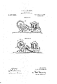
In the accompanying drawings Figure l shows a wiring diagram of a portion of the 9 mechanism particularly the rotating shaft and the parts mechanically associated therewith; Fig. 2 is a wiring diagram of a main control board; Fig. 3 is a wiring diagram of an auxiliary control board; Fig. 4 is a plan 9 view of the rotating shaft and the parts mechanically associated therewith; Fig. 5 is a section on the line 5 5 of Fig. 4, showing the arm shifted into operative position; Fig.
6 is a section on the linetof Fig. 4L, showl ing the arm in inoperated position; Fig. 7 is a plan view of a control board with the casing removed; Fig. 8 is a side elevation of a control board, the casing being shown in section and Figs. 9 and 10 are detail views 1 showing the catch mechanism for the contact levers on the control board.
Referring first to Figs. 4:, 5 and 6 there is al motor M which rotates a shaft S through' `worm gearing W. The shaft S is l of conducting material and carries contact arms or wipers 37, 38, 39, at), All and 4t2. These contact arms are arranged in sets. One set consists of the arms 37, 38, 39 and these arms are arranged at equal angular 1 distances' about the circumference of the shaft S. The second set 40, 41 and 42 arey arranged yat equal angular intervals and the internal intervals in each set is preferably the same. Between the last arm 39 of the l first set and the first arm l0 of the second set is an angular interval greater than that between any two arms within a set. It will appear later that these arms cause the ringing of bells when they make contact and their arrangement is such as indicated above so that when contacts of the first set are used to cause the bells to ring a tens digit of a code number and those of the second set to ring a units digit, the code number may be 13o ing and on this may be placed over the various buttons 101 insignia to indicate the connections made by the levers operated by the respective button. A catch 88 for holding the levers depressed is made in two parts, one part consists of a` strap 107 which is held upright by a lateral arm 108 bearing against a leaf spring 109 mounted on the base of the board. The other portion consists or' a similar strap 110 held upright in similar manner by an arm 111 also resting upon the leai spring 109. The outer ends or' the lever arms L1, etc., are curved so that as the lever arms are depressed `into engagement with the clips they press back the straps 107 or 110 against the pressure of the spring as indicated by dotted lines in Fig.
.9 and when they have reached their depressed position the spring forces the strap back over the end of the levers to hold them down. The signal controlling levers are all of the same length so that after one has been depressed if another is depressed it will push back the strap and release the first lever. This is so as to the levers in any one set, that is between the levers L1, L2 and L3 or the levers L01, L02 and L03. The levers L1, L2 and L3 are used, when a two digitv code number is to be given, to indi,- cate the tens and the levers L01, L02 and L03 to indicate the units. It may, therefore, be necessary to hold two of the lever arms depressed at the same time and vin order to let them be depressed separatelybut held down together the catch is made in two parts, the strap 107 holds down either of the first three leversand the strap 110 holding down either of the last three levers. The lever arm LR engages the clip 13 which is in the circuit of'a release magnet'RM. This lever is curved at the end like the signal levers L1, etc., but is shorter than those levers so that it can be depressed and caught by the strap 107 without releasing the other levers. When so depressed it causes the circuit through the release magnet RM to be closed as soon as the bridge contact 53 on the shaft S bridges the contacts 52 and 54. llVhen the magnetRM is energized it attracts its armature 112 which carries at its eXtreme end a hammer 113 which strikes the arm 108 extending from the strap 107 fieXing the spring 109 and pushes the strap 107 back releasing the contact levers L1, etc. Since the strap 110 is separate from the strap 107 the levers held by the strap 110 wouldvnot be released, but there is a lug 115 evtending from the end of the strap 107 into engagement with the strap 110 so that when the strap 107 is forced back to release the levers it also forces back the strap 110 and so all the levers are released. It will be observed, however, that the lug 115 does not interfere with the independent operation of the strap 110 to catch one of the levers L01,
L02 or L03 after one of the levers L1, L2
or L3 has been depressed.` Indicating lights TL, AL and XL are shown separated from eachother by darkening partitions 116 and each may be provided with a crown light 117 in the'top of the casing for the control board. Only one light may be used on an auxiliary control board while a main control board may have as many lights as there are control boards in the system.
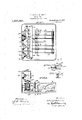
The mechanical construction of the control board and contact mechanism has now been made clear. Attention is directed to Figs. 1, 2 and 3 which show the electrical connections between the various portions of the apparatus. At 0B are indicated diagrammatically bells which may be located at various places throughout the plant where it may be desired to have the signal heard. In the drawing are shown three bells in series and it is to be understood that each bell represents a separate signal station, it being necessary to have but one bell at each station. 0f course, the invention is vnot limited to the use of three bells since any number of signal stations may be served, there being one bell at each station and if desired the bells may be arranged in parallel or they may be arranged series-parallel in groups. The cable 0 connecting the various control boards to the contact mechanism is shown as broken away in the three figures, but it is to be understood that the cable is continuous between `the various mechanisms and that a wire bearing a reference numeral in Figs. 1 or 2 or 3 is a continuation or branch of the wire bearing the same numeral in another figure or iigures. For instance, the wire marked 21 in Fig. 1 is connected with 21 in Fig.` 2 and 21in Fig. 3. There is shown a main control board in Fig. 2 and an auX- iliary control board in Fig. k3 and there may be one or more oeither of these, each being a reproduction of these and the connections being the same. The variouslever arms of the control boards are indicated in Figs. 2
and 3 by dotted lines running from the supporting rods to the vclips and indicating the connections'which are made when the lever arms are closed. It is to be understood, of course, that the lever arms are not all closed at the same time. To cause a signal of a singlekdigit one of the arms L1, L2 or L3 will be used and to cause a signal of two digitsfthere will be used in addition one of the lever arms L01, L02 or L03. For purposes of illustration it may be assumed that the lever arm L3 has been closed.
, The motor circuit may be traced from one side of the line A by the wires 20 and 21 through the cable 0 to the rod R through iso clipsl,;2 and 3 areall connectedto the Wire 22 so ythat if `instead kof the lever arinL3 the lever varm for L2` is in usetheniotor circuit Willbeinade inthe saineway. f` 'y The signal oircuitcniayhe traced from 4,one sidey of the line A'by the vvire 20 andthe Wire through the cable -0 to the rod R` and through the lever -ar1n-L"?fioin which' the `circuit branches', one branchfpassing throughlthe clip 3 andthe Wire22 through7 the cable 0 to the contact linger Vlhenk .the arm 39 lengages they Contactv` linger the circuitwill continue through the shaft S and by the Wire 26 through thecall bells 0B and by` Way of the Wiresl2` and'25 to the other side of the line ,Another ,branch of this circuitY from the `Contact lever L? y goes throughfthe clip 5 and the Wire28 through `thewcahle C. to thecontact inger32. YVhen the contact Win38 lnakescontact Withfthe .linger 32tliis hranchcircuit `will proc-eed to,
the shaft S where itjoinsthe pathy of the. iirst branch passing through the call bells 0B to the other side of lthe linedk The third` branch of the circuit passesfrom the lever arinLs to the clip Gandfthrough the` Wire 29" yand they cable 0 to the` Contact finger3l. lihen ,the contact arm 37 engages thecontact, fingery 3l this branch circuit willcontinuethrough theshaft S Where it vjoints the path f of thetwo other ybranches and passes ythrough the call bells 0B to the other sideofLk the line. It the lever `arm L2 be closed instead ofL the arin L3, fjonly two of the branches1r above traced, namely thosethrough the"`wires 22y and 2`8ivill be closed sincethe` leverarm AL2 engages `the clips `2 yand4 connected With Y those lines, but engages no clip correspond, n ing to thekclip 6 connected `to the line 29" so thatno circuit will be completed when the arm 37 engages its corresponding contact linger 31. In like manner if the, lever varm Llbe closed insteadof the lever larm L3, only onebranch willbe closed, ynamely that through theclip l and the Wire 22 sojlthat the circuit will not belinade lWhen the contact arms 37 and 38 engage their respective contactngers 31 and 32.k It' thelever arm L0S be also closed` three `additional branches ofthesignal circuitwill he closed from lthe rod R to the shafty S from `which they pass throughthe bells 0B to `the other side koi thev line. AOne of these three branches passes throu gh Vthe clip 9 and the Wire 43 and cable 0 to the Contact fniger34 and when the contact armf40 makes contact with the finger 34 the circuit n continues through the shaft; S. Another branch .proceeds through lthe clip Ill andthe `Wire k44 through the cable C to the contact linger 35 and `Whenthe contact" 'arm 'v 4l engages -the :finger 35 thefcurrent continuesthrough the rod S. k'lhethird branch passes through thegclip l2 andthewvire 4.5
through the cable Ctofthe contact linger 3G and when the .contactarin 42 engages the iinf kger l36A the circuit proceeds through the shaft Sl If thelever arm L02 be'closed instead of the arm L0?, only ltwo of' thesey branches,
Willjfbe 'closedthrough the clips 8 and 10, which` are connected to "thefwires 43 'and44 askare theclips Qand il, there beingynol clip engaged ,by the arm L02" corresponding to the/"clip 12 connected .tothe vvire 45 :so that noy circuit Will,beconipleted Whenjthe conf tact alg-m42 ei'igagesitsy inger 36. Vlfthe contact lever L01 beiclosed insteadot the nafmk-ily` those through' thei'vires 43 and 44 Contact' lever L0?" only one of thethree branches ywill lbe closed, :namely that through armsbn the control board.
y"When the circuit is opened by the , lever arms 37, 38, 39, 40,41 or 42 leaving their re-l spective' lingers 3l, 32, 33, 34, 35 and 3G an undesirable spark might be produced, but to 1t yvvill be :remembered thatthe contact iinger's 3l to 36 are connected through the controlboard E tothe Aside of the line bythe Wire, 2l and that vthesha'ft S carrying the contact arms 37 to 42 is connectedby the Wire26 ,through the ybellsfto Ythe Bl side ci? the line. One side of the condenser B0 is; therefore, connected to the Wire l21 by the Wire "46 and the othery side of the condenser vis connectedto the Wire l26 by the Wire 47.
Any spark -ivhich might otherwise -occur heis,j therefore',y avoided. y l y y It vvill be remembered that` the Wires from the auxiliary control board AE 4alsoiarenconn nectedy to the. cable Cy and, therefore,A the corresponding `Wires on Fig. vv3 are marked with thesarne reference numerals as on Fig.
tween the contact arms and contact `fingers y l es favoid this I connectin' the bell circuit andr parallel to said opening a Ycondenser BC.
2..y It Will thus be readilyjseen that `the saine signal y circuits Vmay be made by y, operating thecorresponding contact levers on lanr'au'xilf iary call board.- n f y v v l/Vheneither of the Contact levers L15 L2,
theindicating lamp lLthence through the ,Wire 87 and the cable@ to the point 55 and thence through Wire to the B side of the L? are closed a branch circuit is made from `the clips 192er 3 through fthe wlreBG and line. 'Another branch is also closed through' Wire 22 c'ahle C to yauxiliary controlv board AE through the lamp AIL .and Wire y87 and cablegC to point V55 and thence by Wire 56 vto the yB side of vthe line. Thuslanips ist operation an additional branch circuit is made from the levervarm through the catch bar 88 and the wire 89 `which passes through the *cablek C to the control board E and through the lamp lAL and by the wire 90,
to thev wire 87 which passes through the cable C tothe point 55 and thence through the wire 56 to the yB side of the line.y In Fig. 2 only one lamp AL has to show vbut obviously 'one may be added for each auxiliary control board in use and may be connected up with its respective board as is the lamp AL into the board AE.y l, 4
To stop the apparatus the release lever LR or ALR, etc., may be closed.` The circuit for the release magnets may be traced from one side of the line through the wire 20 and the wire 21 through the cable C to the rod R andthe lever arm LR, to the clip 13, which it engages, through the'wire 48 to the pointy 49 where the circuit'branches, one branch passing by the wire 50 through Athe release magnet'RM and the wire 51 through the cable C to the contact inger52 through the bridge contact 53, when the rotation of the shaft S has brought it in the proper po-V sit'ion, through the contact finger 54 to the point 55 and through the wire 56 tothe B side of the line. From the point 49 the other branch passes through the wire 57 and the cable C to the point 49a on the control board 'AE and by the wire 50 through the release magnet ARM and the wire 51 through the cable C where it joins the other branch passing through the contact mechanisms 52, 53 and 54 to the B side of the line. All the release magnetson all the control boards are thus energized and all the leverk arms released when the bridge piece 53 is brought into contactwith the fingers 52 and 54 by the rotation of the shaft S. A similar releasing circuit may be made by closing the lever ALR on an, auxiliary control board.
In order 'toavoid an undesirable spark passing between the lever arml LR and the clip 13.*when the lever arm is released there is provided a condenser RC connected across the opening. It will be remembered that the lever armLR is connected to the Aside of the line through the rod R and the wire 21 passing through the cable C, while the clip 13 is connected to the B side of the line through thewires 48, 50 and themagnet. One side o f the condenser RC is, therefore,
connected to the A side of the line by thel wires 58, 5,9 and 60 and the other side of the condenser is connected through the wire 57 to the point 49 between the wires48 and "50.KA This prevents the spark which might otherwise pass between the clip 13 .and
the
contact lever LR.
, When the time contact 67 is closed a circuit is completed from the A side of the line through the wires 5,8, 59 and 68 through the time contact 67 and the wires 69 and 70 through the time magnets TM and the wire 71 to the B side of the line. This lifts the arm 92 and causes the bridge 65 to connect the spring contacts 63 and 64. When the arm is raised it is held elevated by the catch 94 until it is mechanically released'by the pin 98 after the shaft S has made the pretact 67 thus avoiding the spark which might otherwise form at the opening of the contact.
' The circuit through the motor when the time signal is in operation may be traced from the A side ofthe line through the wires 58, 61 and 62 to the spring contacts 63 and 64 bridged by the raised bridgcpiece 65 rand through the wires 66 and 24 through the motor 'M and by the wire 25 to the B side of the line.
The signal circuit when the time contact is in operation maybe traced from the A side of the line through the wires, 58, 61 and 62 to the spring contact linger 7 4 which is engaged vby the projections ony the time wheel 75 as it rotates from which the circuit passes through the shaft S to the wire 26 to the signals CB and thence through the wires 27 and 25 to the B side of the line.
The circuit through the fire Contact 76 may be traced from the A side of the line through the wires 58, 59, 60 and 77 through the lire contact 76 andthe wire 7 8 through the lire magnets FM and by the wires 79 and 71 to the `B side of the linc. This raises the arm 92 and causes the bridge 8O to connect the spring contacts 81 and 82 in which. position it is held until it is mechanically tripped after the shaft S has made the predetermined number of revolutions. The motor circuit may then be traced from the A side of the line through the wires 58, 61 and 83 through the contacts 81, 80 and82 and through the wires 66 and 24 through the motor M and the wire 25 to the B side of the line. The signal circuit may be traced from the A sideof the line through the wires 58, 61 and 83 through the contacts 81 and 8O to the contactfinger 84 which engages the fire alarm wheel 85 as the shaft S rotates from which the circuit -continues through the wire 26 and the signals CB through the wires 27 and 25 tothe B side of the line.
crmtrol hoard.
The koperation of the device `will ,be readily understood. One of the levers L1, L2 or L3 on onel of the control boards may be depressed and held down by the catch 88. 'llliis will close the circuit through the. motor lv'l which will immediately'begin torotate the shaft At the same :timethe indicati--l ing lights IL, on the various control boards` will be lighted and if 'an auxiliary control board isoperatedfits corresponding light All) on the main i controlxboard fwill be lighted,` Inconnection therewith one of the levers L01, L02, ,L03 maywormay not be depressed. The shaft S as itfrotatesswill bring the/contact arms to l2 carriediby it in contact with theirrespectiye contactfinn gers, thus completing one `or more `ofthe branch circuits through :the signals and causing signals at' the 'various stations in accordance with the selection made on the control board. This operation willi continue and the signal be repeated untilafter a lever RL on one of the 'control boards has been depressed and the bridging kpiece 53 has been brought, by the rotationl ofthe shaft, into contact `with its fingers 52, eli-When Lthe re-` lease magnets Will operate to `release the lever catches and open allthe circuits bring ing the motor and apparatus to `rest and eX;`
tinguishing the lights on the various control boards. Either of the extraordinary for emereenc signals ma `be brouehtfinto o 3- eration at any time by closure of the circuit through the corresponding magnetsTM `or FM and the motor started the `bridging contacts carried by the karmatures of the magnets. The rotationof theshaftby the motor will cause theteeth on the `Wnees to engage the contact fingersand close the sig-r nal circuits. This operation will continue until the circuit is openedby"themechanical trip when the star Wheel has been rotated.
The control board hasbeen illustrated as made up of 'two sets of Contact"A levers each setcontaining three levers.y Itis obvious, however, `that the invention is ynot `limited to this number as there'may `be more orless than three levers in eachr set andk there` may` beonly one or more than twosetsion each Numerous i other changes and alterations may bey made without Jde-1 nectingthe fingers tothe other sidevof the source! of current, and means for connecting the shaft to the fingers one after the other.
2. Signals, a shaft, means for `electrically connecting the signals and shaft, ausource of current, means for electrically connecting the signals to one side of a sourceof current, contact fingers, means for selectivelyconnectingthe fingers to the other side yof the source of current, a motor for rotating the shaft to conn 4ct it With the fingers one afte'r cuit before the shaft contacts with any finger, and means for opening the motor circuit only after the shaft has contacted with alllthefingers.
' 8.. Signals, a shaft, means for electrically connecting thesignals and shaft, source ofv current, means for electrically connecting the signals to one side of a source of current, contact fingers, means for selectively con-r necting the fingers to the other side of the source of current, a magnet for causing the motor circuit-to open, and means carried by the shaft to energize the magnet circuit only after the shaft has contacted.- With all the fingers,
4. Signals, a shaft, means for electrically connecting thezsignals and shaft, a source of current, means" for electrically connecting thesignalsto one side of a source of current, contactfingers, means for selectively rconnecting the-fingers to the other side of the source of current, wipers on the shaft, .and
,means for contacting the Wipers and ythe lingers one after the other.'
5. Signals, a shaft, means for electrically connectiiig'the signals anddshaft, a source of current,` means for `electrically connecting' the signals to one side of a sourceof current, stationary contact lingers, meansfor connecting the fingers to the other side of thesource ofcurrent, and means for connecting the shaft to the fingers. t
G.y Signals, a shaft, means for electrically connecting'the signals andshaft, a source ofcurrent, means for electrically connecting the signals toene sidefof a'source of current, contact lingers, means for selectively connecting the fingers to the other side of thesourceof current,\amotor for rotating the shaft to connect 1t with thefingers one after the other, and means for closing thek motor circuitbefore the shaft contacts with any finger. f
`7. Signals, a shaft, means for electrically connecting the signals and shaft, a source of current, means for electrically connecting the signals 4to one side of a source of current,
Contact k fingers, means for selectively connecting :the fingers to the otheryside ofthe source 'of current, a. magnet for causing the motor circuit to open, and means vcarried by the shaft to energize the magnet circuit.`
"SJA motor, a shaft rotated by the motor,
theother, means for closing the motor cirico los
lle
contact arms carried at different angular p0- sitions on the shaft, stationary contact fingers all on one radius of the shaft and engaged by the contact arms as the shaft rotates, a source ofl current, means for connecting one or more of the contact fingers to one side of a source of current, signals, and means for connecting the shaft to the other side of the source of current through the signals. Y
l 9. A motor, a shaft rotated by the motor, contact arms yon the shaft, contact fingers engaged by the contact arms as the shaft rotates, a source of current, means for connecting the contact fingers to one side of a source of current, signals, and means for connecting the shaft to the other side of the source of current through the signals.
10. A motor, a shaft rotated by the motor, contact arms carried at d iiferent angular positions on the shaft, stationary contact fingers engaged successively by the contact arms as the shaft rotates, a source of current, means for connecting the contact lingers to one side of a source of current, signals, and means for connecting the shaft to the other side of the source of current vthrough the signals.
11. A motor, a shaft rotated by the motor, contact arms carried at different angular positions on the shaft, stationary contact fingers all on one radius of the shaft and engaged successively and respectively by the contact arms as the shaft rotates, a source of current, a plurality of means for selectively connecting the contact fingers to one side of a source of current, signals, and means for connecting the shaft to the'other side of the source of current through the signals. s n
12.k Signal circuits, a plurality of successively acting contact devices in the circuits,
lmeans for repeatedly actuating said contact devices, other contact devices in the circuits, and selective means for closing the other contact devices to determine Which of the successively acting contact devices shall energize the circuits.
13. Signal circuits, a plurality of contact devices in the circuits, means for repeatedly actuating said contact devices, other contact devices in the circuits, means for closing the other contact devices, and means for holding them closed.
14. Signal circuits, a-plurality of successively acting contact devices in the circuits, means for repeatedly actuating said contact devices, other contact devices in the circuits, and means for closing the other contact devices, and means for stopping said ractuating 15. Signal circuits, a plurality of. successively acting contact devices in the circuits, means for repeatedly actuating said contact devices, other contact devices in the circuits,
and means for closing the other contact` devices.
16. A motor, a shaft rotated by the motor, contact arms carried at different angular positions on the shaft, stationary contact fingers all on one radius of the shaft and engaged by the contact arms in succession as the shaft rotates, a plurality of control boards, clips on each board, means for electrically connecting each contact hnger to one or more clips on each board, a source of current, a rod on each board connected to one side of a source of current, spring restrained contact levers on each rod each to engage one or more of the clips, a catch on each board to hold the levers when in contact with a clip, magnets for releasing the catch on each board, a circuit for the magnets, a yclip on each control board and in the magnet circuit, a lever carried by each rod to engage the last mentioned clip Without releasing the catch, a contact carried by the shaft engaging a contact linger in the magnet circuit to close it after all the arms have engaged the fingers, a circuit for the motor passing through some of the clips and levers, signals, and means for connecting the shaft through the signals-to the other side of the source'of current.
17. A motor, a shaft rotated by the motor, contact arms carried at different angular. positions on vthe shaft, stationary contact fingers all on one radius of the shaft and engaged by the contact arms as the shaft rotates, a plurality of control boards, clips on each board, means for electrically connecting each contact finger to one or more clips on each board, a. source of current, a rod on each board connected to one side of a source of current, spring restrained contact levers on each rod each to engage one or more of the clips, a catch on each board to hold the levers Whenin contact with a clip, magnets for releasing the catch on each board, a circuit for the magnets, a clip on each control board and in the magnet circuit, a lever carried by each rod to engage the last mentioned clip, a contact carried by the shaft engaging a contact finger in the magnet circuit, means on the control boards to indicate ythat a board is operated, a circuit for the tates, a plurality of control boards, clips on each board, means for electrically connecting each contact finger to one or more clips on each board, a source of current, a rod on each board connected to one side of a source of current, spring restrained contact levers on ,each rod each to engage one or more of the clips, a catch on each board to hold the levers When in contact with a clip, magnets for releasing the catch on each board,'a circuit for the magnets, a clip on each control board and in the magnet circuit, a' lever carried by each rod to engage the last mentioned clip,
`a contact carried by they shaft engaging a `contact finger in the magnet circuit, means to indicate that a board is operated, and means to indicate Which'board is operated,
a circuit for the motor passing through some of the clips and levers, signals, and means" for connecting the shaftthrough the signals to the other side of the source of current.
19. A motor, a shaft rotatedby the motor, contact arms on the shaft, stationary contact fingers engaged by the contact arms as the shaft rotates, a plurality of control boards, means for electrically connecting each contact finger to each board, a source of current, a spring restrained contact lever onv each board to connect it to one side of a source of signals copies of this patent maybe brained fior current, magnets for releasing the `contact levers yon all the boards, ka contacten each control boardinthe magnet circuit, a contact carried by the shaft engaging a contact finger in the magnet circuit,a circuit for the motor kpassing through the vrcontrol boards,`
and a conductor leading from thek shaft through the signalsto the other side of the source of current.
20. A motor, a shaftv rotated byv the motor, contact ngers, means carried by the shaft to engage the contactfingers,v a plurality of controlk boards, means on each board for completingy a circuit through the various contact fingers, means on eacliboard `to hold closed the'circuit completingr means, a magi Witnesses:
net for releasing the holding means on each i board, means on each control board vfor closing a contact in a circuit through all the magnets, a contact carried by the shaft engaging a contact finger in the magnet cir# cuit, a circuit for the motor passing through for closing a plurality of contacts in the circuit, a plurality of control boardsy for the means each comprising means for selectively closing contacts in the signal circuit, means on each control board for indicating that a control board is operated, and means for indicating Which of the control boards is operated.
23. Signals, a circuit for the signals, a .plurality of contacts in the signal circuit, means forclosing each of certain contacts at uniform time intervals and leaving longer time intervals between certain contacts, means' for selecting Which contacts shall be effective tok operate signals.
Signed at Cleveland, this 27th day of August, 1913.
GORDON FOX.
KARL FENNING, -FLoiuNE EVANS.
five cents each, byvaddressing the Commissioner oi. Patents. Washington, ID. 0..4
'TONY M. JEWETT.
Priority Applications (1)
| Application Number | Priority Date | Filing Date | Title |
|---|---|---|---|
| US78726713A US1237320A (en) | 1913-08-29 | 1913-08-29 | Signal device. |
Applications Claiming Priority (1)
| Application Number | Priority Date | Filing Date | Title |
|---|---|---|---|
| US78726713A US1237320A (en) | 1913-08-29 | 1913-08-29 | Signal device. |
Publications (1)
| Publication Number | Publication Date |
|---|---|
| US1237320A true US1237320A (en) | 1917-08-21 |
Family
ID=3305139
Family Applications (1)
| Application Number | Title | Priority Date | Filing Date |
|---|---|---|---|
| US78726713A Expired - Lifetime US1237320A (en) | 1913-08-29 | 1913-08-29 | Signal device. |
Country Status (1)
| Country | Link |
|---|---|
| US (1) | US1237320A (en) |
Cited By (2)
| Publication number | Priority date | Publication date | Assignee | Title |
|---|---|---|---|---|
| US2442947A (en) * | 1944-01-24 | 1948-06-08 | Kellogg Switchboard & Supply | Code-call system |
| US20060257524A1 (en) * | 2003-05-06 | 2006-11-16 | Gumlink A/S | Method for producing chewing gum granules, a gum compositon extruder and granulating system, and a chewing gum products |
-
1913
- 1913-08-29 US US78726713A patent/US1237320A/en not_active Expired - Lifetime
Cited By (2)
| Publication number | Priority date | Publication date | Assignee | Title |
|---|---|---|---|---|
| US2442947A (en) * | 1944-01-24 | 1948-06-08 | Kellogg Switchboard & Supply | Code-call system |
| US20060257524A1 (en) * | 2003-05-06 | 2006-11-16 | Gumlink A/S | Method for producing chewing gum granules, a gum compositon extruder and granulating system, and a chewing gum products |
Similar Documents
| Publication | Publication Date | Title |
|---|---|---|
| US1237320A (en) | Signal device. | |
| US1823960A (en) | Totalizing counter | |
| US1163346A (en) | Signal system. | |
| US2612551A (en) | Paging system | |
| US944003A (en) | Electric signal system. | |
| US2838749A (en) | In-and-out register and paging system | |
| US461371A (en) | Fire-alarm apparatus | |
| US933412A (en) | Electric call and alarm system. | |
| US386772A (en) | Half to e | |
| US1248749A (en) | Electric signal system. | |
| US598172A (en) | barron | |
| US1194525A (en) | Electkic signaling means | |
| US365726A (en) | Electric circuit-testing apparatus | |
| US443475A (en) | Electeic cash register | |
| US1194571A (en) | Eise-alarm system | |
| US1058261A (en) | Signaling mechanism. | |
| US144643A (en) | Improvement in telegraph apparatus for automatic signaling | |
| US447195A (en) | Annunciator and indicator system | |
| US338697A (en) | Nventdr | |
| US369810A (en) | patten | |
| US1052389A (en) | Annunciator and signal system. | |
| US422654A (en) | Electric time-alarm and annunciator | |
| US486149A (en) | Test-circuit for burglar-alarm systems | |
| US654967A (en) | Electric signal and fire-alarm. | |
| US414879A (en) | And charles a |