US1237312A - Internal-combustion engine. - Google Patents
Internal-combustion engine. Download PDFInfo
- Publication number
- US1237312A US1237312A US72043912A US1912720439A US1237312A US 1237312 A US1237312 A US 1237312A US 72043912 A US72043912 A US 72043912A US 1912720439 A US1912720439 A US 1912720439A US 1237312 A US1237312 A US 1237312A
- Authority
- US
- United States
- Prior art keywords
- chamber
- valve
- piston
- air
- crank
- Prior art date
- Legal status (The legal status is an assumption and is not a legal conclusion. Google has not performed a legal analysis and makes no representation as to the accuracy of the status listed.)
- Expired - Lifetime
Links
Images


Classifications
-
- F—MECHANICAL ENGINEERING; LIGHTING; HEATING; WEAPONS; BLASTING
- F02—COMBUSTION ENGINES; HOT-GAS OR COMBUSTION-PRODUCT ENGINE PLANTS
- F02B—INTERNAL-COMBUSTION PISTON ENGINES; COMBUSTION ENGINES IN GENERAL
- F02B25/00—Engines characterised by using fresh charge for scavenging cylinders
Definitions
- WITNE88E8 INVENT n G. W. DONNING. INTERNALCOMBUSTION ENGINE. APPLICATION nuzo sup :4. ma.
- Another object is to design'an engine so 'that the parts thereof are accessible and I 1,337,312; r V
- This invention reates to internal .com-
- the invention hasseveral importantobects 1111 view, among which, may be'mentioned that of constructing'an en e which embodies all of the desirable eatures of the"twocycle and four-cycle engines and which,-.yet, eliminates most'if not all of the known defects and obj ectio'n's inherently existing in each of these types of englnes;
- Another object is to so constructthe parts -fl as to make the engine non-reversible and, also, practically fool-proof.
- Another ,ob'ect is. to construct the engine include coolingand scaveng-'- 1n ing means and a suction strokeduring the exhaust; an air compression stroke ing operation duringthe work stroke.
- the v invention resides, in one. aspect, in a structure comprising a cylinder, a piston, and a crank shaft operating therein; the cylinder being provided with explosion and air. conix pression chambers at opposite sides of the piston-the compress on chamber being adapted to receive atmospheric air only;
- cranks in
- re 1 is a view in front elevation show-' this instance, beingshow'n as placed at prac- 'tically 120 apart;
- Fig. 3 is a view, partly'in, plan, and partly in horizontal section, the section being taken on the line 2--2, Fig. 2;
- Figs. and 6 are views in elevation, partly Fig. 4is a fragmentary view ofone form fchamber 17 Manifestly, by reason of thefiring-chamber 16" and into a compression reciprocatory movement of the piston in the cylinder, these chambers are alternately elongated. .I prefer to form the crank-case of.
- cranks-case relatively'small dimensions in order that I may obtain a somewhat greater compression therein than can be effected in the ordinary form of crank-case.
- the interior dimensions of the cranks-case may be varied by the inclusion or omission of the space fillers, al-
- crank-case may also utilize any other means, whenever necessary, to change the working area of the crank-case to effect" an increased or reduced compressive action therein.
- means may include the lubricant which is disposed in the crankv case, and the addition or reduction of which obviously will correspondingly reduce or increase the working spacein the crank-case;
- controlling-devices may be employed and, in the drawings, I have illustrated difierent forms thereof.
- valve 18 which is of exoeedingly simple construction and 'yet is an effective type of controlling device which I elect to use.
- This valve comprises a tubular member, closed at one end and carrying a stem 18, and having an elongated aperture 18* extending longitudif desirable, the valve may be provided with a plurality of circumferential grooves 18" adapted to receive one or more expansion rings 18 iEncompassing the stem 1-8 and adapted to'take up wear that may occur during a long continued operation of the valve, a washer 19, 3
- valves 18 are adapted to be disposed in a valve-orifice 20 formed in the walls of the;
- abutment 21 which is formed by making the inner end of the orifice of less diameter than the bore of the orifice itself, as shown in 3 Figs; :3 and 'i'.
- This abutment limits the rearward movement of the valve 18 and also provides means for preventing leakage around the outer surface of the valve.
- This construction also permits a film of oil to'be' maintained around the valve to insure its easy action and also to prevent leakage.
- i'nthe casing beneath the valve orifice 20 is a recess 22 in which is seated a springrcontrolled T-shaped valve-tightening member 23, preferably encircled by an expansion ring,24.
- the T-shaped member is provided with a bore 25 extending its entire length.
- the T-shaped portion of the memher is formed'with a concaved depression 26 adapted to op'eratively register with the aperture 18 in the valve 18.
- the wall 22 surrounding the 'reces 22 is provided on its outer edge 22 with screwthre'ads, upon whichis to besecured a coupling-member 27 f adapted to hold the extremity of a pipe 28, the end of which is en'- larged and provided with an annular incut adapted to be seated normally.
- a coupling-member 27 f adapted to hold the extremity of a pipe 28, the end of which is en'- larged and provided with an annular incut adapted to be seated normally.
- the T-shaped member 23 is understood that the enlarged end of the ipe 28 permits the coupling-member 27 to'tig tly' engage the sameand prevent leakage.
- Encircling the T-shaped member 23 and adapted to bear against the end of the pipe 28 is a spring 29, said spring also bearingagainstthe ring 24 or some portion of the body-po .tion of the T-shaped" member.
- the function of this spring is to maintain the T-shaped member tightly in engagement with the
- the-parts are selfadjusting to take up such wear and insure a tight joint.
- valve is in a location where the fluid is passing into the cylinder, the
- T-shaped member tends more readily to direct thegas into the bore 25 whereas,.in the In the first instance, the depression 26 in the latterinstance, it permits the gas to separate out somewhat whileenteringthe valve 13.
- Figs. 9 I may employ a'modified form of construction illustrated in Fig. 9, which contemplates the omission of. the T-shaped member 23 and the employment, in conjunction with the valve '18, of a dilierent form I of wear take-up.
- the fvalveorifice is provided with "an arcuate cut-out in which" is seated an appro riately formed takeru member 31 provide on its outer. edge wit a feather 32- adapted tobe casing.
- the recess22 is retained but is unobstructed by any intermediate instrumentality.
- Means are rovided for actuating the valves and, pre erably, such means include a connecting rod 36 operatively connected at one end to the valve-stem 18 and at its opposite end to a lever 37 suitably pivoted upon a post or standard 38, and provided with a roller-carrying stud 39 adapted to traverse a groove in a cam-disk 41 fast on the crank-shaft.
- the post 38 is carried by a movable support 41' mounted on a suitable part of 4 thefc linder-casing, the position of which may e controlled by an adjusting instrumentality, suchl as a screw 42.
- an adjusting instrumentality suchl as a screw 42.
- the lever 37 is provided with'a plurality of holes 37 a into one or another of which the connecting rod is secured, and, by this means,thelengt of movement of the connecting rod is varied and, thus, the movement of the "alve, 40 It is to be understood that the constructionjust described may be used in connection with any of the valves employed in my on 'ne.
- the cam-disk 41 is provided, also, on its opposite side with a cam-groove 43 in which a roller-carrying stud 44 is adapted to travel, as shown in Fig. 4.
- the stud 44 is carried by a lever 45, preferably of construction and operation similar to that of the lever 37.
- the cam-- ves 40 and/43 are 0 different forma tion; but their general function is the same, namely, to client a POSitlVG and certain movement of their respective connecting rods and,'thus, of the valves to which the respective connecting rods are attached.v These instrumentalities efiect a.
- the valves are adaptedto be operated, preferably, a film of lubricantconstantly.
- they in being housed in closeproximity to the cooling-channels or 3 spaces of the cylinder, they; m. k pt.
- the side casings 9' are -closed;by a plate 46 through which thecrank-shaft extends.
- the side walls of one or more of the cylindercasings are provided withchannels 48 having ports 49 and 50 adapted to be controlled by the movement and position of the piston 2 as the same reciprocates: Air having been introduced into the chamber 12 in the man- Iner presently to be described-the same will be caused to pass from 7 said chamber up into the lower portion ofthe-ignition chamher through the channel 48, the condition of the piston in relation to the ports. 49 and .50
- the purpose of introducing compressed air into the ignition chamber, at its lower portion, is to provide a mediumtherein which will be adapted to displace from the ignition chamber all of the charge that .may not have been otherwise removed therefrom through the exhaustports.
- a still further function of the air is to provide an additional amount of air within the ignition chamber, and of the purest quality, to mix with the char e subsequently intror
- a further function of the air is to 'cool the ignition chamber "and the piston.
- the charge, having been introduced into the firing or ignition chamber 16 is ignited 40 by means of an igniting device 53 which may be of any appropriate form and timed to produce a spark at an predetermined time in relation to the posit1on f the piston.
- the charge is introduced into the firingchamber through the inlet-port 54 (Fig. 3") which is controlled by a formof valve, like 18," already described.
- a formof valve like 18
- a closed casing from which extends, preferably from its lower end, another conduit 56 leading into each compression chamber 12 and in which conduit is arranged one or 'more valves [57 preferably like the valve 52, shown in Fig.v 6.
- the carbureter is shown in detail in Fig. 11; and, besides including the casing 55, is divided by a spring-comi trolled n'alve 58 which divides the casing into two chambers and B0, one of which chambers, '59, is rmix'm" chamber, while the other, 60, is a li ui -receiving cham- 55 her.
- Fuel is introduce into the carbureter through the nozzlefii, controlledby the inlet-valve 62, in the usual manner.
- Air is introduced into the chamber 60 through the-- port 63, into whichthe conduit 56 leads, and which is adapted to supply'that portion of the air to the carbureter which is not withdrawn from the compression chamber and introduced into'the ignition chamber, as already described.
- the air is thus supplied from the combustion chamber be-' fore the other portion thereof is permitted to pass into the ignition chamber.
- This air, thus'introduced into the carbureter is compressed andthus operates to open the valve 1 r 58 so that it and the fuel can enter the mix- 30 ing chamber 59 to be mixed therein.
- Prac tlcal use of carbureters has shown that, at
- valve 58 with a pendant bafiling element 64.
- reticulated element 65 preferably in the form of wiremesh, the function I of which is to further connninute themateria'ls passing into the mixing chamber, wherefore their admixture may be more readily accomplished.
- a throttleelement 66 for throttling the gas, as usual.
- the operator may increase the'wbrk, ing'space of the chamber12 by withdrawing, through the pet cock 11, any desired amountof thev fluid contamed in the 'bottom of the chamber 12.
- eta-a cock B8 is'provi ed, preferably, in the bottom of the carbureter.
- an exhaust-port 69 Arranged. in any suitable portion of the 'tion' hamber is an exhaust-port 69, as I 73. If desired, outstandin pins or projec- .tions 73 maybe emplove The function so 'of these is to radiate the heat of the exa method for cooling the exhaust-gases beast-gases, temperature of the exhaust gases'and, thus, cool the chamber and thereb reduce the heat-units contained therein. his provides within the mufilercasmg, so that a smaller and simpler form of .mufller may employed.
- 59' mufller is rovided with an expansion chamas it risesduring ber 71.- is enables me to dispense with the muflier cut-out, so-called, which isused to f relieve the pressure. within the ignition chamber of t e gases acting on the piston the. ethaust-stroke,- as is well understood. I obtain practically'the equivalent result of a mufller cut-out by re-" leesin' the gas from the ignitlOn chamberinto t e expansion chamber and such gas may be permitted to escape therefrom at anyback-pressure;
- cooling facilities are incor orated, and more enabled to reduce the number of cylinders (without reducing pacity of the engine.) and, thus, reduce corthe power-producing car'espondingly the weight and space occupied V by the engine, I can employ any appropriate.
- I ma if desired,-utili'ze a tubular radiator like t at illustrated inj FigsI2-and 12, which may be connectedto the en inethe pipes 74 and 75. Having reduce the weight and spajce,-as aforementioned, I; am enabled to correspondingly increase the water t orage Q I facilities.
- a stub-shaft 7 8 journaled in any suitable part of the ngine and provided.
- roller-carrying stud '79 adapted to travel back and forth in a cani-slot-SO pivoted toany suitable part of the engine.
- the lever is also attached to a connecting' rod .82, correspondin valve (to which 'the connecting-rod 82 'jlfs attached), the lever 81 is prorlded with a series of holes 81 in one or another of which v the connectingerod is secured. 4
- the inion 84 5 is relatively larger than the pinion 83 in order to roduce a slower operation of the valve, as 18 usual in fourcle engines in relation to the operation oi the crank-shaft.
- Fast on the stub-shaft 85 i's a cam-element 87.
- the shaft would carry one of these cams at each of its ends.
- a roller 88 mounted on the lower end of a lever 89 pivoted at 90, and which is p'rovided with one or more holes 89 in one ,or another of which is' attached a valve-com nectin rod 91.
- This valve is.for the purpose of preventing the production of a vacuum which would be au ed by the down-stroke of the piston which, in the four-cycle type of engine,
- valve-operating mechanism and the valye which it controls is also well adapted for use in the ordinary four-cycle type of engine. It would be desirable, however, if'used therein to divide the crankcase i'nto independent compartments resembling. those shown in Fig. 2, so that air may be compressed therein for use in the c'arbureter and also for accelerating the return of the piston. In this-cbnnection, I may also state "that the form of carburetor herein disclosed. may also be effectually used in connection with theordinary form of four-cycle engine.
- the motor is of thetwocycleform and that it comprises three cyl inders, (such as shownin the drawings) and assuming, also, 'that a. rich 'mixture has 5.
- the igniting device is brought into operation to ignite the charge. This actuates the piston to IBroduce a'work-stroke thereof.
- the air ortvalve 52, Fig.- 6 closes and the air in c amber 12 iscompressed, whereu an e-certain portion of the air flows-to the arbureter to cooperate with the-gasolene flowing thereso into to make the mixture, and inwhich car bureter this mixture in heldmomentarily under reasonably safe compression, to rien and be released at the, roper time. hear the end of the 'work-stro a, the valve-mech- 05 'anism (including disk i1-,-cam-groove 48,
- the i nition chamber "the i nition chamber. Immediately following t ie opening of the exhaustQthe air-ports reaches the end of its work-stroke; whereupon com ressed air from chamber 12) flows into the ring-cha n er and forces out the burned gases, and assists in cooling the interior o the cylinder and thus clearing the same for a new mixture. As the piston rises in .its up-stroke, the fresh air ports are again closed thereby. Any air remaining in the crank-case will, b reason of bein compressed (and the air-ports being coscd) give the piston a slight acceleration, after which a vacuum is created in the crank-case and more air is caused to floutinto it through the air-port 52.
- Fig. 14 I have shown, diagrammatically, the various functions performed, as 0 just described, during onecomplete revolution of the crank in asingle cylinder of a motor of the two-cycle type.” Thereinis noted the successive operations of spurkin compression, admission of mixture, etc, an also, the rate of speed ofthe piston in its down and up strokes.
- cranks in the three cylinders are arranged on the shaft in a relation of 120, so that before one cylinder begins to exhaust, another is sending -the piston on its work-stroke and this gives perfect mechanical balance.
- Fig. 15 In the dia ramm'atic view, Fig. 15, I have 12:; illustrated t eresulting'overlapping of the power-stream, that is, the available developed force or energy thus making a continuous stream of power and reducing vibrations'to the inn. It will be underno me that A n this a delight te l m e can v muflleigthe" they are d' cult to throttle down. (2).
- a cylinder providedwith a cofn session chamber at one end and a firin amberat the other end, a valve-controlle ports in the firing amber at one end thereof, and ports in the comre'ssion chamber opening into the firing chamber at the other end I: ereof, the piston operating to cover thedifierent. ports at predetermined times, and positivel actuated means to close the valve contro ed ports when covered. and open them when uncovered by said piston.
- An eng ne comprising piston mounted for movement therein; said cylinder being provided with an inlet and withan exhaust port openinginto one end thereof andprovided at its' opposite end with an opening for the .adm1ssion of a scavenging medium; valve mechanism for positively controllin ,the inlet and exhaust *ports; and means of the valves after the piston derg 6.
- An. engine comprising ,a cylinder,- a
- An engine comprising ,a cylinder, a piston mounted for movement ,therein; said cylinder being provided with" an inlet and exhaust port opening into one end thereof and with an opening for a scavenging medium disposed in its opposite end; a com-.
- pression chamber in communication with 'said opening for sa d scavenging medmm;
- An internal combustlon engine comprising a three-cylinder two-cycle motor, each'cylinder having a firing chamber and a compression chamber; said firing chamber being provided with an.
Description
a. W1D'0NNl NG. INTERNAL COMBUSTION ENGINE. APPLICATION FILED $21 1.14. 1912.
.Phtented Aug. 21,1917.
Q SHEETS-SHEET I.
I (SEW. DONN ING.
INTERNAL COMBUSTION ENGINE APPLICATION FILED SEPT-14.19. 1,237,312.
Patented Aug. 21, 1917;
4 SHEETS-SHEET 2.
q] rum/ran I M w W 2mm G. w-. momma. INTERNAL COMBUSTION ENGINE, APPLICATION FILED stPT, 14; 1912 Patented Aug." '21, 1917.
WITNE88E8: INVENT n G. W. DONNING. INTERNALCOMBUSTION ENGINE. APPLICATION nuzo sup :4. ma.
1,237,312, PatehtdAugL2lQl917."
4SIlEETS- SIIEET-4.
' size of p A. Another object is to design'an engine so 'that the parts thereof are accessible and I 1,337,312; r V
- To all whom it may concern:
\ acitizen :of -the United States, residing at- Stamford, in-theicounty ofFairfield and State of Connecticut, have invented certain GEORGE w. nomvme, or s'rnuronn, connnc'rrcu'rl nrrnnlvn-comnus'rron ENGINE,
"Beit known that I, GEOBGE Wi Donnlne,
' new and useful Improvements inInternalbusti'on engines, generally, and, more sp'e- Combustion Engines, of which the following is a specification, reference being bad thereinto the acoom nying drawing.
This invention re ates to internal .com-
cifically, to the'two-cy cle type thereof. The invention hasseveral importantobects 1111 view, among which, may be'mentioned that of constructing'an en e which embodies all of the desirable eatures of the"twocycle and four-cycle engines and which,-.yet, eliminates most'if not all of the known defects and obj ectio'n's inherently existing in each of these types of englnes;
and -'this contemplates. the introduction of a certain novel features to increase the power and -.eflicien'cyof the engine,'-and whereby use of a great variety offuelsis permitted and economy'in fuel and reduction of noise and friction in use, and the-reduction 1n weightand, size and number of'partsof the structureilare effected.
i A er object-is to obtain .a max mum of power with: a minimumpf weight and the parts and of the use of fuel. a
' easily removed.
Another object is to so constructthe parts -fl as to make the engine non-reversible and, also, practically fool-proof.
i so, that it may for compressing pure air for the pression Y A further object i to construct the vari I ous parts of the engine so that they are in-' terchangeable.
Another ,ob'ect is. to construct the engine include coolingand scaveng-'- 1n ing means and a suction strokeduring the exhaust; an air compression stroke ing operation duringthe work stroke.
Another object is to so operate the parts as toavoid a fullsuction stroke and a; comstroke within the firing-chamber. Another object is to provide a chamber purposeof effecting a more perfect scavenging and cooling of the firing-chamber after each f work stroke and, thus, clear aid chamber tion.
during the work stroke; and a gas forming or mixfor. the reception of anew mixture and, in
consequence, prevent contamination of the new mixture with the old charge.-
I Specification e s Pat n 'Patented'Aug. 21, 1917.- lp plication fled September 14,1912. ser1a1'1vo.'7ao.4aa.
With these and other objects in view, the v invention resides, in one. aspect, in a structure comprising a cylinder, a piston, and a crank shaft operating therein; the cylinder being provided with explosion and air. conix pression chambers at opposite sides of the piston-the compress on chamber being adapted to receive atmospheric air only;
there being a channel or channels leading from the compression chamber portion ofthe firing-chamber, said channel to thelower or channels (mouthing into .the. firingchamber) being adapted to be uncovered by the piston at the end of each work stroke which it performs;, a combined carbureter an d mixture-conveyer outside ofthe cylinder and which is' dependent upon com- Y pressed 'air to produce and effect movement of the mixture therefrom into the. firing-1' chamber; and a positively-driven valvemechanism adapted to have an accelerated movement, and to cooled and oiled, and
' running practically noiselessly.
''The invention resides also 1n the novel form and aggroupmentof the parts, the
predetermined timing of operation oi. the
movable element thereof, ,etc., all as hereinafter more fully described and claimed.
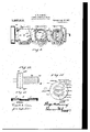
In the accompanying drawings, I have so I illustrated but one of many possibleembodi ments of my invention. It is to be understood that the principles andsalient'features of the invention are capable of being embodied in various other forms'of structure and still be within the spirit of the inven- In the drawin Fi g t e cylinder-casing, with practically all the parts-housed within the same;
" lf ig. 2 is a view, partly in vertical section,
illustrative of my invention as embodied in a three-cylinder structure; the cranks, in
Fig. 3 is a view, partly'in, plan, and partly in horizontal section, the section being taken on the line 2--2, Fig. 2;
of the valve-operating mechanism, etc-; I
Figs. and 6 are views in elevation, partly Fig. 4is a fragmentary view ofone form fchamber 17 Manifestly, by reason of thefiring-chamber 16" and into a compression reciprocatory movement of the piston in the cylinder, these chambers are alternately elongated. .I prefer to form the crank-case of.
relatively'small dimensions in order that I may obtain a somewhat greater compression therein than can be effected in the ordinary form of crank-case. The interior dimensions of the cranks-case may be varied by the inclusion or omission of the space fillers, al-
a ready referred to; and I mayalso utilize any other means, whenever necessary, to change the working area of the crank-case to effect" an increased or reduced compressive action therein. Such means may include the lubricant which is disposed in the crankv case, and the addition or reduction of which obviously will correspondingly reduce or increase the working spacein the crank-case;
If either alcohol or kerosene is employed as a' fuel for the engine, a higher compression and higher temperature are required. It is to be understood'that I may employ as manycylinders as desired; In each in stance, however, the cylinders and crankcases are so designed as to be independent.
.To control, in a positive andcertain manner, the supply of charge to the firing-chammay perform their functions in proper relation to the operation of other" parts of the engine.
Various forms of these controlling-devices may be employed and, in the drawings, I have illustrated difierent forms thereof.
. In Fig. 10, I have shown,-on an enlarged nally in the walls of the tube.
scale, a form of valve 18 which is of exoeedingly simple construction and 'yet is an effective type of controlling device which I elect to use. In Fig. 3, the particular locations of this'valve are revealed: This valve comprises a tubular member, closed at one end and carrying a stem 18, and having an elongated aperture 18* extending longitudif desirable, the valve may be provided with a plurality of circumferential grooves 18" adapted to receive one or more expansion rings 18 iEncompassing the stem 1-8 and adapted to'take up wear that may occur during a long continued operation of the valve, a washer 19, 3
preferably cupsshaped, may be used. These valves 18 are adapted to be disposed in a valve-orifice 20 formed in the walls of the;
cylinder-casing,and provided with an abutment 21 which is formed by making the inner end of the orifice of less diameter than the bore of the orifice itself, as shown in 3 Figs; :3 and 'i'. This abutment limits the rearward movement of the valve 18 and also provides means for preventing leakage around the outer surface of the valve. This construction also permits a film of oil to'be' maintained around the valve to insure its easy action and also to prevent leakage.
'Formed i'nthe casing beneath the valve orifice 20 is a recess 22 in which is seated a springrcontrolled T-shaped valve-tightening member 23, preferably encircled by an expansion ring,24.' The T-shaped member is provided with a bore 25 extending its entire length. The T-shaped portion of the memher is formed'with a concaved depression 26 adapted to op'eratively register with the aperture 18 in the valve 18.
The wall 22 surrounding the 'reces 22 is provided on its outer edge 22 with screwthre'ads, upon whichis to besecured a coupling-member 27 f adapted to hold the extremity of a pipe 28, the end of which is en'- larged and provided with an annular incut adapted to be seated normally. It will be 28 into which the T-shaped member 23 is understood that the enlarged end of the ipe 28 permits the coupling-member 27 to'tig tly' engage the sameand prevent leakage. Encircling the T-shaped member 23 and adapted to bear against the end of the pipe 28 is a spring 29, said spring also bearingagainstthe ring 24 or some portion of the body-po .tion of the T-shaped" member. The function of this spring is to maintain the T-shaped member tightly in engagement with the outer face of .thevalve 18, and it also tends to force the end of the pipe 28 into tight engagelnent with the coupling-member 27.
in the event of anywear, the-parts are selfadjusting to take up such wear and insure a tight joint.
- Itwill be understood that the, passage of the fluid or gas, whichever it may be, entrs the valve and passes through the .perture 18, thence. through the bore 25 of the T- By this means, a tight joint is formed and,
shaped member, andthence into the pipe 28,- h
from whichit is led to any desired point. If, however, the valve is in a location where the fluid is passing into the cylinder, the
path of travel is through the pipe 28. and
thence through the bore 25 into the valve.
T-shaped member tends more readily to direct thegas into the bore 25 whereas,.in the In the first instance, the depression 26 in the latterinstance, it permits the gas to separate out somewhat whileenteringthe valve 13. I
In lieu of the construction disclosed in Figs. 7 and 8, I may employ a'modified form of construction illustrated in Fig. 9, which contemplates the omission of. the T-shaped member 23 and the employment, in conjunction with the valve '18, of a dilierent form I of wear take-up. In this instance, the fvalveorifice is provided with "an arcuate cut-out in which" is seated an appro riately formed takeru member 31 provide on its outer. edge wit a feather 32- adapted tobe casing. In this instance, the recess22 is retained but is unobstructed by any intermediate instrumentality.
' dapted to be secured to the exterior of the cylinder-casing and .to overlie the recess a tain the valve in proper operative position" againstthe abutment 21, already described. Means: are rovided for actuating the valves and, pre erably, such means include a connecting rod 36 operatively connected at one end to the valve-stem 18 and at its opposite end to a lever 37 suitably pivoted upon a post or standard 38, and provided with a roller-carrying stud 39 adapted to traverse a groove in a cam-disk 41 fast on the crank-shaft. Preferably and as shown, the post 38 is carried by a movable support 41' mounted on a suitable part of 4 thefc linder-casing, the position of which may e controlled by an adjusting instrumentality, suchl as a screw 42. Bythe adjustment of the post 38, the position of the roller-carrying stud may be changed and, in this manner, the time of movement of the connecting rod and, thus, of the valve to which it 18 connected, is varied. The lever 37 isprovided with'a plurality of holes 37 a into one or another of which the connecting rod is secured, and, by this means,thelengt of movement of the connecting rod is varied and, thus, the movement of the "alve, 40 It is to be understood that the constructionjust described may be used in connection with any of the valves employed in my on 'ne.
referably and as shown, the cam-disk 41 is provided, also, on its opposite side with a cam-groove 43 in which a roller-carrying stud 44 is adapted to travel, as shown in Fig. 4. The stud 44 is carried by a lever 45, preferably of construction and operation similar to that of the lever 37. I For purposes presently to be ex lained, the cam-- ves 40 and/43 are 0 different forma tion; but their general function is the same, namely, to client a POSitlVG and certain movement of their respective connecting rods and,'thus, of the valves to which the respective connecting rods are attached.v These instrumentalities efiect a. rotative movement of the valves in the'valve-orifices, 6 alreadyfdescribed, and "are thereby housed in such manner that the valves are adaptedto be operated, preferably, a film of lubricantconstantly. Moreover, in being housed in closeproximity to the cooling-channels or 3 spaces of the cylinder, they; m. k pt.
I seated in a groove 33' formed in the cylindercool in every desirable manner and for an 1 alwa s.
tween two cylinders, are provi ed with double cams, whereas, when .they are not so arranged, they preferably carry but a,
sin le cam;
adapted' to be housed within the casin2s9 and 10, respectively, and in which, as already state cod reason. Practical" observa-'. tion. has s own that inengine structures with which I am famalianthe valves become oil and keeping them coo they are effective ,The disks 41, where they are dis osed be:
referably and as shown, "these disks are Y i a suitable lubricant may be employed in. order to permit. the Ldisks'to run continuously, if desired,.'- in an oil bat-h. This lubricant may be introduced through I orifices 9' and 10,' and -may be j removed therefrom through-j the-cri-fices 9" and 10".
, The side casings 9'are -closed;by a plate 46 through which thecrank-shaft extends.
Preferablyand as shown in Fig. 2, Bab
bitt metal bearings 47 .are. provided in theca'sing for the crank-shaft. These bearings are, as shown, formed in two parts and, being provided with flanges, interlock with the casing so that they are maintained in position against displacement by any lateral movement of the crank-shaft or by the action of compressed air which is introduced into the air or compression-chamber 12.
Preferably, and as shown in Figs. 2 and 3,
ice
the side walls of one or more of the cylindercasings are provided withchannels 48 having ports 49 and 50 adapted to be controlled by the movement and position of the piston 2 as the same reciprocates: Air having been introduced into the chamber 12 in the man- Iner presently to be described-the same will be caused to pass from 7 said chamber up into the lower portion ofthe-ignition chamher through the channel 48, the condition of the piston in relation to the ports. 49 and .50
controlling the movement of the air from the one chamber intothe other. The purpose of introducing compressed air into the ignition chamber, at its lower portion, is to provide a mediumtherein which will be adapted to displace from the ignition chamber all of the charge that .may not have been otherwise removed therefrom through the exhaustports.
A still further function of the air is to provide an additional amount of air within the ignition chamber, and of the purest quality, to mix with the char e subsequently intror A further function of the air is to 'cool the ignition chamber "and the piston.
duced into and ignite in this ignition chamber. Thus a smaller amount of the mixture is required for theexplosion to operate the piston and, moreover, being uncontaminated by vvguiy residual gas that would beveramained in the ignition chamber if it had notbeen properly scavenged by this air, a more efiicient'power stroke is developed.
It is generally recognized that the use of 5 a mufller produces a resistance to the proper exhaust of the spent gases from the ignition chamber. By reason of thefact, however,
that I introduce air into the ignitionvchamher at a pressure in exoess of this resistance produced by the muflier, I am enabled to clear the ignition chamber of'every particle of the unspent gases. By reason of this fact,
it is evident that much of the carbonaceous tter that would otherwise adhere to the parts with which it comes in contact is not *developed to the degree usual; but that which is formed is largely if not entirely blown out throu h the exhaust.
' It is now in or er to describe the means for 7 2c introducing the a1r 1nto the chamber 12:
pheric air in su cient quantity to satisfy the vacuum. The descending movement of the iston effects a compress on of the air thus introduced into the chamber and the valve 52 is thus automatically closed, whereupon the compressive action on-the air is continuous and is completed so that, as'the piston uncovers the port 50, the greater portion of 85 the compressed air, thus produced, passes through the channel .48 and into the ignition.
chamber, as" already described.
The charge, having been introduced into the firing or ignition chamber 16 is ignited 40 by means of an igniting device 53 which may be of any appropriate form and timed to produce a spark at an predetermined time in relation to the posit1on f the piston.
The charge is introduced into the firingchamber through the inlet-port 54 (Fig. 3") which is controlled by a formof valve, like 18," already described. Each of the cylinders, if more than one is employed, is rovided with one of these inlet-ports; and into each port extends the pipe orconduit 28 leading from a carbureter 55 which,
,in this instance, includes a closed casing from which extends, preferably from its lower end, another conduit 56 leading into each compression chamber 12 and in which conduit is arranged one or 'more valves [57 preferably like the valve 52, shown in Fig.v 6. The carbureter is shown in detail in Fig. 11; and, besides including the casing 55, is divided by a spring-comi trolled n'alve 58 which divides the casing into two chambers and B0, one of which chambers, '59, is rmix'm" chamber, while the other, 60, is a li ui -receiving cham- 55 her. Fuel is introduce into the carbureter through the nozzlefii, controlledby the inlet-valve 62, in the usual manner. Air is introduced into the chamber 60 through the-- port 63, into whichthe conduit 56 leads, and which is adapted to supply'that portion of the air to the carbureter which is not withdrawn from the compression chamber and introduced into'the ignition chamber, as already described. The air is thus supplied from the combustion chamber be-' fore the other portion thereof is permitted to pass into the ignition chamber. This air, thus'introduced into the carbureter, is compressed andthus operates to open the valve 1 r 58 so that it and the fuel can enter the mix- 30 ing chamber 59 to be mixed therein. Prac tlcal use of carbureters has shown that, at
times, during. introduction of the fuel, it
does not spatter properly and the proper direction. W1th'a view to augmentmg the spattering action within the car= bureter, I provide the valve 58 with a pendant bafiling element 64. 'Overlying the valve 58 is a reticulated element 65, preferably in the form of wiremesh, the function I of which is to further connninute themateria'ls passing into the mixing chamber, wherefore their admixture may be more readily accomplished. Housed within the casing 55 is a throttleelement 66 for throttling the gas, as usual. a
It will now be understood, from the foregoing, that the' fuel, having entered 'the' carbureter and been thoroughly and well a,
mixed, and therein ripened, a portion '100- thereof passes through the conduit 21 into the ignition chamber and there exploded,
as already described.
In order that the operator may determine the exact pressure ofthe mixture withinioe the carbureter, so that its rising above the point of efiecting spontaneous combustion may be prevented,l provide a gage 67 ,of any appropriate form, and which isoperated by the gas pressure'within the carbureter in a manner that will be understood. If the operator observes that""t he mixture isfrising to a dangerous point-fend as it is undesirable to permit a waste of the .mixture by permitting it to pass into the ignition chamber and be. consumed therein without desirable result, and which condi' tion of aflairs would indicate that the coins 'pression in thechamber 12 is runningtoo high,-the operator may increase the'wbrk, ing'space of the chamber12 by withdrawing, through the pet cock 11, any desired amountof thev fluid contamed in the 'bottom of the chamber 12.
As the compressed lair, which isfnatnrally 12 bf relatively high temperature, flp'asses hrough the chamber 60,.v and, thus, comes Qincontact with any portion of the fuel vthat may nothave' passed into the chamber 59. this y, all *of the fuel which is intro- 1so duced into the carbureter is utilized, in-
stead of a portion of it beingfwasted, as
frequently now occurs. As the gas or liquid might becbflow from the carburetor, if,
means were not provided to prevent the same, I may rely upon the valves 57 to control this.
To drain the carbureterofany liquid or mixture which may be in the chamber 60-- if it be necess'a to make repairs, eta-a cock B8 is'provi ed, preferably, in the bottom of the carbureter.
Arranged. in any suitable portion of the 'tion' hamber is an exhaust-port 69, as I 73. If desired, outstandin pins or projec- .tions 73 maybe emplove The function so 'of these is to radiate the heat of the exa method for cooling the exhaust-gases beast-gases, temperature of the exhaust gases'and, thus, cool the chamber and thereb reduce the heat-units contained therein. his provides within the mufilercasmg, so that a smaller and simpler form of .mufller may employed. This rapidcooling, acting in con- ]unctlon with the chamber itself, in advance 0 of the mufller reduces back-pressure upon exhaust-noise, produces a the piston during each exhaust-stroke of the engine. It has been found, on practical operetion,-that the ordinary form of mumer that is adapted complete] the gases into the ignition chamber and against'the piston. To provide a receptacle into which these gases may ass and, thus, prevent such'back-pressure o the'gases, the
59' mufller is rovided with an expansion chamas it risesduring ber 71.- is enables me to dispense with the muflier cut-out, so-called, which isused to f relieve the pressure. within the ignition chamber of t e gases acting on the piston the. ethaust-stroke,- as is well understood. I obtain practically'the equivalent result of a mufller cut-out by re-" leesin' the gas from the ignitlOn chamberinto t e expansion chamber and such gas may be permitted to escape therefrom at anyback-pressure;
time, irrespective of the position of the piston. I thereby efi'ect a complete silencing of the noise without the objectionable disadvantages-already pointed out of--the muiiler In addition, by eliminating In divided cooling flanges resulting in a cooling of theto silence the ack-presure of .this mu filer back-pressure against the piston,
the'volume of the-unexhausted com ressed gases that remain within the firing-c iamber at the time the exhaust-valve is closed, is I greatly reduced, 'so that when. the piston lacgins its suction stroke it almost immediately begins to draw in the mixtureand with su perior results since thereis less of the foul matterremaining to expand and contaminatesa1dm1xture. r
and in view of the fact, also, that airparticularly, in view of tie fact that I-am 75 In view of the factthat, in my structure, the are exhausted more rapidly'than 1 3 ,v
cooling facilities are incor orated, and more enabled to reduce the number of cylinders (without reducing pacity of the engine.) and, thus, reduce corthe power-producing car'espondingly the weight and space occupied V by the engine, I can employ any appropriate.
form of radiator for coolingthe water; but
I ma if desired,-utili'ze a tubular radiator like t at illustrated inj FigsI2-and 12, which may be connectedto the en inethe pipes 74 and 75. Having reduce the weight and spajce,-as aforementioned, I; am enabled to correspondingly increase the water t orage Q I facilities.
lVhile I have herein exemplified certain embodiments of my invention, it nevertheless to be' under'stood that the various parts and mechanisms-may be modified to a considerable degree and yet be within the.
spirit of, my invention.
For instance," in lieu of'the form of' valveoperating mechanism already described, I.
may, for a two-.cycle'engine, for example,
utilize the form xshownin Fig. 5,1which contemplates the mounting of a pinion/Z6 on the crank-shaft 3'. -Adapted tomeshwith this pinion is a corresponding pinion '77,
carried by a stub-shaft 7 8 journaled in any suitable part of the ngine and provided.
with a roller-carrying stud '79 adapted to travel back and forth in a cani-slot-SO pivoted toany suitable part of the engine.
1x01 formedin one end of a bell-crank-lever 81:-
The lever is also attached to a connecting' rod .82, correspondin valve (to which 'the connecting-rod 82 'jlfs attached), the lever 81 is prorlded with a series of holes 81 in one or another of which v the connectingerod is secured. 4
The structure already described. is that '5 permit a greater or' ess movement of the" 1 1 5 which I contemplate utilizing particularly with a two-cycle engine It is to be understood that itis also adapted for use witha quired; being in respect -to the-- valve-operating mechanism and, also, the upper-portion of the cyllnders. In ieu of the forms of v 1 valve-operatin mechanisms already do scribed-,1 re or to employ that which is shown in ig. 6, which includes-a pinion four-cycle engine, the only modificationrea 83 fast on the crank-shaft, a second inion' 84 fast on a stub-shaft 85 journals in a bracket 86 secured-to any suitable part of the engine. As will be seen, the inion 84 5 is relatively larger than the pinion 83 in order to roduce a slower operation of the valve, as 18 usual in fourcle engines in relation to the operation oi the crank-shaft. Fast on the stub-shaft 85 i's a cam-element 87. In some instances, the shaft would carry one of these cams at each of its ends. Adapted tortraverse the active portions of said cam is a roller 88 mounted on the lower end of a lever 89 pivoted at 90, and which is p'rovided with one or more holes 89 in one ,or another of which is' attached a valve-com nectin rod 91. The second modification of the c inder as aforementioned, merely contenip ates the provision of an additional port 92 opening into the ignition chamber d in which port operates a valve 93 of a form similar to that marked 52, Fig. 6. This valve is.for the purpose of preventing the production of a vacuum which would be au ed by the down-stroke of the piston which, in the four-cycle type of engine,
would correspond to the suction-stroke, and
which vacuum would, in my type of engine, be produced because during the downstroke of the .p'ston, the inlet-valve is closed.
This orm of valve-operating mechanism and the valye which it controls is also well adapted for use in the ordinary four-cycle type of engine. It would be desirable, however, if'used therein to divide the crankcase i'nto independent compartments resembling. those shown in Fig. 2, so that air may be compressed therein for use in the c'arbureter and also for accelerating the return of the piston. In this-cbnnection, I may also state "that the form of carburetor herein disclosed. may also be effectually used in connection with theordinary form of four-cycle engine.
Cycles of operation.
Assuming that the motor is of thetwocycleform and that it comprises three cyl inders, (such as shownin the drawings) and assuming, also, 'that a. rich 'mixture has 5. passed through the carbu-reter chamber, 59 and conduit 28 into the firing-chamber, the igniting device is brought into operation to ignite the charge. This actuates the piston to IBroduce a'work-stroke thereof.
uring such a work-stroke, the air ortvalve 52, Fig.- 6, closes and the air in c amber 12 iscompressed, whereu an e-certain portion of the air flows-to the arbureter to cooperate with the-gasolene flowing thereso into to make the mixture, and inwhich car bureter this mixture in heldmomentarily under reasonably safe compression, to rien and be released at the, roper time. hear the end of the 'work-stro a, the valve-mech- 05 'anism (including disk i1-,-cam-groove 48,
'49 and are opened by the piston as it lever 45, and its connection) operates to open the exhaust-valve for releasing any residual gases or unexpended energy from.
"the i nition chamber. Immediately following t ie opening of the exhaustQthe air-ports reaches the end of its work-stroke; whereupon com ressed air from chamber 12) flows into the ring-cha n er and forces out the burned gases, and assists in cooling the interior o the cylinder and thus clearing the same for a new mixture. As the piston rises in .its up-stroke, the fresh air ports are again closed thereby. Any air remaining in the crank-case will, b reason of bein compressed (and the air-ports being coscd) give the piston a slight acceleration, after which a vacuum is created in the crank-case and more air is caused to floutinto it through the air-port 52. During a considerable part of this suction-operation, under the piston, the exhaust'port will be open; but, when the crank is in the vicinityof 45 of upper deadcenter, the exhaust-valve 94 commences to close and, simultaneously, the inlet'valve 95 commences to open, and will remain open while the crank is passing through 15 to 25, more or less whereupon the piston will cover the inlet and exhaust-ports after which the. inlet valve operating-mechanism 95 operates to close the.inletport. Through the last or remainin degreesof movement of the crank,'tliere 1s a slight compression of the mixture in the firing-chamber; and, v during that period of compression, or later, the mixture can be ignited. Thus, it can be seen that. I have obtained, in a two-cycle engine, the equivalent of the full work-suctioncompression and exhaust-strokes of a founcycle motor; and, with the novel ms terms of scavenging, cooling, etc, etc., already described, the results will be supe' rior in every particular.
In Fig. 14, I have shown, diagrammatically, the various functions performed, as 0 just described, during onecomplete revolution of the crank in asingle cylinder of a motor of the two-cycle type." Thereinis noted the successive operations of spurkin compression, admission of mixture, etc, an also, the rate of speed ofthe piston in its down and up strokes.
It is to be understood that the cranks in the three cylinders, shown in Figs. 1-3, are arranged on the shaft in a relation of 120, so that before one cylinder begins to exhaust, another is sending -the piston on its work-stroke and this gives perfect mechanical balance. i
In the dia ramm'atic view, Fig. 15, I have 12:; illustrated t eresulting'overlapping of the power-stream, that is, the available developed force or energy thus making a continuous stream of power and reducing vibrations'to the inn. It will be underno me that A n this a delight te l m e can v muflleigthe" they are d' cult to throttle down. (2).
' exhaust-port, the new charge is ignited v explosions occur in the crank-case, thus tons during cylinder, and O that at the opposite end. n this figure is represented the .power' stroke of cylinder the teas are being exhausted preparatory to the admission of thenew miX- ure.
- It' is-rather enerall admitted by those familiar with the" followin reasonsi (1): Because, while running at high speed, and even without a, varies, fuel is wasted, and
They miss fire, back-fire, and frequently because of lea-kagesround the piston into the crank-case, or because the inlet-port is opened practically simultaneously with the racking and almost stopping the motor, all
of which necessitates heavy construction.
(8), They cannot develop full or steady 5 Bower because of the above reasons and also I V a too quicklyf-resulting ina large portionof the being left in the i g ch'amber which contaminates the new mix- *"""tu'ror.th e-e'xplosion force is"greatly weakened,- soslthat the full force of the workstroke'is not possible, and as the gasesare removed-too s00n,"theforce developed by p use-of the fact that, as they exhaust tionthe explosion is'dissipatedbefore the piston has made. two-thirds of its work-stroke.
. ton wor formed at one ,side of said-p T WhatIl One of the objects ofmy invention is to overcome these and other recognized de fects and to produces motor of the twocycle type well adapted not only for vessale, but, forfactbry,'aeroplane and automobile n'se.-
criticisms against-the ordi nary four-cycle' motor are, thatthey are of t weight, they include a The principal valves, and :they set premature ignition due to overheated cy i der, high compression, etc, during the compression-stroke.
' It will be obvious tliat my invention overcomes thesedefepts.
e um 18: Ch-In an internal combustionen no, the mbination of acylinder provi ed with Torts adf'gce nt its top, ,a reciprocat ng PIS- ns h n ee s-9 si -ch m a i pression-chamber disposed Ii B 'Z OPPOQEB side of said piston, a crank ft operating in the compges'sion-chainbe va for cfintro ling sal' hrts va m'c a: connectiiig with and the enema e art, t attwo-cycle motors are-for the most part unsatisfactory,.and for msm con and crank-shaft an atom. M in m. rali of directions to yl'ect a -tive movemen of the valves in op'te directions,
and .a carburetor communicating with so i 'tion chamber andfwith said compression- 2. Infan-internalcombustion en e, the
ports adacent its top, a reciprocating on-chain r side ofsaidtpistoma crank- (Writing in the compression-chamber, valves for con-- trolling and ports, valve-operatingmecha' combination of a cylinder provi ed withthe opposite with-said valves audit-ho crank-shaft an actuatsble thereby in a pluchamberandj with said com ression-chamber, and valve-mechanism or contro communication between said carburetor an i said compression ohambe'n 8. In an internal combustion engine, a cylinder .rovided with a set of valve-controlled i et and exhaustports at one endand a set of rts at the opposite .end, and a piston withiifthe cylinder-and movable to cover each setof ports in succession.
'4. In aninternal combustion engine, a cylinder providedwith a cofn session chamber at one end and a firin amberat the other end, a valve-controlle ports in the firing amber at one end thereof, and ports in the comre'ssion chamber opening into the firing chamber at the other end I: ereof, the piston operating to cover thedifierent. ports at predetermined times, and positivel actuated means to close the valve contro ed ports when covered. and open them when uncovered by said piston.
5. An eng ne comprising piston mounted for movement therein; said cylinder being provided with an inlet and withan exhaust port openinginto one end thereof andprovided at its' opposite end with an opening for the .adm1ssion of a scavenging medium; valve mechanism for positively controllin ,the inlet and exhaust *ports; and means of the valves after the piston derg 6. An. engine comprising ,a cylinder,- a
piston withm -the c linder,
a cylinder, a
or 'efl'ectin operation,
I as covered -or uncovered the port openings in the cylinpiston mounted for movement therein; said said openin for said scavenging, medium;
means efiec ing a communication between said compression and said inlet port; a carbureter included in said means; 7
means for retaining a portion of said scavenging medium under compression in said.
'carbureter during a portion of the stroke of said piston; and independent means for opening communication between the inlet port and the interior of thecylinder after the piston has uncoveredthe inlet opening.
7. An engine comprising ,a cylinder, a piston mounted for movement ,therein; said cylinder being provided with" an inlet and exhaust port opening into one end thereof and with an opening for a scavenging medium disposed in its opposite end; a com-.
pression chamber in communication with 'said opening for sa d scavenging medmm;
means effecting a communication between said compression chamber and said inlet port; a carbureter included in said means;
means for retaining a portion of said scaven ing medium under compression in said covered t e inlet opening; and independent means for opening the exhaust port valve after the piston has uncovered said exhaust port open ng. An internal combustlon engine comprising a three-cylinder two-cycle motor, each'cylinder having a firing chamber and a compression chamber; said firing chamber being provided with an. inlet and exhaust port'opening into one end thereof and with a communication between said compression chamber and said firin chamber opening into'the outer end thereo valve mechanism for positively opening and closing said inlet and exhaust ports; a crank shaft, a conmotion between each piston and said crank shaft, each connection being at ap' rox'imately an angle of 120 degrees in re ation to the next preceding connection; each piston being operable to uncover the communication between the compression chamber andfiring chamber at the limit of its movement in one direction and at the limit of itsmovement in its opposite direction to cover said inlet and exhaust openings; and means connected with said crank shaft for operating the valves in the inlet and exhaust ports after the piston has covered or uncovered the inlet and exhaust portopenings. a
In testimony whereof I afiix my signature in presence of two" witnesses. f
GEORGE W. DONNING.\
Witnesses: a
ALVAHD. MEAD,
PERCY E. CANT'RELL.
Priority Applications (1)
| Application Number | Priority Date | Filing Date | Title |
|---|---|---|---|
| US72043912A US1237312A (en) | 1912-09-14 | 1912-09-14 | Internal-combustion engine. |
Applications Claiming Priority (1)
| Application Number | Priority Date | Filing Date | Title |
|---|---|---|---|
| US72043912A US1237312A (en) | 1912-09-14 | 1912-09-14 | Internal-combustion engine. |
Publications (1)
| Publication Number | Publication Date |
|---|---|
| US1237312A true US1237312A (en) | 1917-08-21 |
Family
ID=3305131
Family Applications (1)
| Application Number | Title | Priority Date | Filing Date |
|---|---|---|---|
| US72043912A Expired - Lifetime US1237312A (en) | 1912-09-14 | 1912-09-14 | Internal-combustion engine. |
Country Status (1)
| Country | Link |
|---|---|
| US (1) | US1237312A (en) |
Cited By (3)
| Publication number | Priority date | Publication date | Assignee | Title |
|---|---|---|---|---|
| US3358663A (en) * | 1967-05-18 | 1967-12-19 | Miclo Walter | Two-cycle internal combustion engine |
| US4765304A (en) * | 1987-10-26 | 1988-08-23 | Outboard Marine Corporation | Internal combustion engine with compressed air collection system |
| US5062396A (en) * | 1987-06-26 | 1991-11-05 | Institut Francais Du Petrole | Device and method for introducing a carburetted mixture under presssure into the cylinder of an engine |
-
1912
- 1912-09-14 US US72043912A patent/US1237312A/en not_active Expired - Lifetime
Cited By (3)
| Publication number | Priority date | Publication date | Assignee | Title |
|---|---|---|---|---|
| US3358663A (en) * | 1967-05-18 | 1967-12-19 | Miclo Walter | Two-cycle internal combustion engine |
| US5062396A (en) * | 1987-06-26 | 1991-11-05 | Institut Francais Du Petrole | Device and method for introducing a carburetted mixture under presssure into the cylinder of an engine |
| US4765304A (en) * | 1987-10-26 | 1988-08-23 | Outboard Marine Corporation | Internal combustion engine with compressed air collection system |
Similar Documents
| Publication | Publication Date | Title |
|---|---|---|
| US1527166A (en) | Two-cycle internal-combustion engine | |
| US1952881A (en) | Internal combustion engine | |
| US5299537A (en) | Metered induction two cycle engine | |
| US1237312A (en) | Internal-combustion engine. | |
| US676449A (en) | Gas, petroleum, or like internal-combustion engine. | |
| US1286435A (en) | Internal-combustion engine. | |
| US3046960A (en) | Internal combustion engines | |
| US1725418A (en) | Four-cycle internal-combustion engine | |
| US1907470A (en) | Internal combustion engine | |
| US2905159A (en) | Internal combustion engine | |
| US1652266A (en) | Internal-combustion engine | |
| US1350135A (en) | Two-stroke internal-combustion engine | |
| US1907354A (en) | Two-cycle internal combustion engine | |
| US1102045A (en) | Internal-combustion engine. | |
| US1695714A (en) | Constant-volume and constant-compression engine and method of operating same | |
| US1501884A (en) | Internal-combustion engine | |
| US1210286A (en) | Internal-combustion engine. | |
| JPS6149130A (en) | 4-cycle internal-combustion engine | |
| US880704A (en) | Gas-engine. | |
| US1383689A (en) | Explosive-engine | |
| US1431188A (en) | Internal-combustion engine | |
| US1458771A (en) | Internal-combustion engine | |
| US1144433A (en) | Internal-combustion engine. | |
| US1174765A (en) | Two-cycle combustion-engine. | |
| US809081A (en) | Internal-combustion engine. |