US1237304A - Automatic steam-jet furnace-stoker. - Google Patents
Automatic steam-jet furnace-stoker. Download PDFInfo
- Publication number
- US1237304A US1237304A US64130211A US1911641302A US1237304A US 1237304 A US1237304 A US 1237304A US 64130211 A US64130211 A US 64130211A US 1911641302 A US1911641302 A US 1911641302A US 1237304 A US1237304 A US 1237304A
- Authority
- US
- United States
- Prior art keywords
- jet
- blower
- steam
- nozzle
- fuel
- Prior art date
- Legal status (The legal status is an assumption and is not a legal conclusion. Google has not performed a legal analysis and makes no representation as to the accuracy of the status listed.)
- Expired - Lifetime
Links
- 239000000446 fuel Substances 0.000 description 63
- 239000012530 fluid Substances 0.000 description 43
- 230000001276 controlling effect Effects 0.000 description 14
- 230000007246 mechanism Effects 0.000 description 13
- 230000001105 regulatory effect Effects 0.000 description 9
- 238000004891 communication Methods 0.000 description 8
- 239000007789 gas Substances 0.000 description 6
- 230000033001 locomotion Effects 0.000 description 5
- XLYOFNOQVPJJNP-UHFFFAOYSA-N water Substances O XLYOFNOQVPJJNP-UHFFFAOYSA-N 0.000 description 5
- 239000003245 coal Substances 0.000 description 4
- 229920000742 Cotton Polymers 0.000 description 3
- 244000299507 Gossypium hirsutum Species 0.000 description 3
- 239000003546 flue gas Substances 0.000 description 3
- 238000009434 installation Methods 0.000 description 3
- 238000004326 stimulated echo acquisition mode for imaging Methods 0.000 description 3
- 238000010304 firing Methods 0.000 description 2
- 235000014443 Pyrus communis Nutrition 0.000 description 1
- 208000036366 Sensation of pressure Diseases 0.000 description 1
- 244000273618 Sphenoclea zeylanica Species 0.000 description 1
- 208000027418 Wounds and injury Diseases 0.000 description 1
- 238000005266 casting Methods 0.000 description 1
- 230000005494 condensation Effects 0.000 description 1
- 238000009833 condensation Methods 0.000 description 1
- 238000010276 construction Methods 0.000 description 1
- 230000006378 damage Effects 0.000 description 1
- 206010022000 influenza Diseases 0.000 description 1
- 208000014674 injury Diseases 0.000 description 1
- 210000004185 liver Anatomy 0.000 description 1
- 239000000463 material Substances 0.000 description 1
- 230000010355 oscillation Effects 0.000 description 1
- 230000000630 rising effect Effects 0.000 description 1
- 239000004576 sand Substances 0.000 description 1
Images


Classifications
-
- B—PERFORMING OPERATIONS; TRANSPORTING
- B65—CONVEYING; PACKING; STORING; HANDLING THIN OR FILAMENTARY MATERIAL
- B65G—TRANSPORT OR STORAGE DEVICES, e.g. CONVEYORS FOR LOADING OR TIPPING, SHOP CONVEYOR SYSTEMS OR PNEUMATIC TUBE CONVEYORS
- B65G53/00—Conveying materials in bulk through troughs, pipes or tubes by floating the materials or by flow of gas, liquid or foam
- B65G53/34—Details
- B65G53/52—Adaptations of pipes or tubes
- B65G53/525—Adaptations of pipes or tubes for conveyance in plug-form
Definitions
- Thisinvention relatesto that class ⁇ of automatic stokers wherein granular fuel is automatically fed from a hopper propel ling steam jet by kwhich the fuel is d1str1byuted. throughout the furnace grate area.
- @ne of the main objects of this invention is to locate the steam jet in a .blower whereby the said jet will draw airor Lfurnace gases into said blower ⁇ andymingle with it to form the propelling jet.
- the coal is delivered v within the olower and willy be propelled or projected over the furnace grate by the combined steam and air jetf
- the elocity of the steam jet is somewhat ⁇ reducedjand the propelling jet is increased in volume, ⁇ I have found this to be a much vmore satisfactory fuel propelling jet than a pure steam jet as a ypure steam jet has too great a vvelocity and not sufficient volume to be accuratelycontrolled for the proper distribution of the fuel.
- Anoth xr object of the invention is to provide a peculiar shape of blower to be used in connection with the steam jet, whereby the proper distribution of the coal will be secured.
- N n y A further obj ect of the invention is to provide a novel form offuel feeding means for delivering the fuel to the blower apparatus.
- Astill further object of the invention is to provide a simply constructed and efficient to the blower apparatus.
- a further object ⁇ of the invention is to construct the blowerapparatus and the fuel ⁇ .means for controlling the supply ⁇ of steam feeding means, by. ⁇ which the fuel is .fed to y the blower, in such manner that the blower apparatus may be connected to a fire door ⁇ and the fuel feedingmeans mounted upon the-furnace front so that the door carrying the blower apparatus may be opened at any time withoutv disarranging the ⁇ feeding
- whiclrwill ap* pear hereinafter.
- blower ifr open to the atmosphere ywill de-, liver toov much air over the fire and in those cases I have arranged to deliver hot flue gases to the blower instead of air; or deliver the hot gases with air. This serves the purpose of giving volume. to the'jet and thereby reducing its speed,-without introducing any cold air over the fire. i
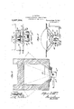
- Figure l isa 'front elevation with my stoker applied; y y Fig. 2 a vertical longitudinal sectional view of the stokerfand ,the front ,portion yof the furnace on line 'II-II of Fig. l;
- Fig. 3 a horizontal sectional viewof the furnace fire box and the blower approximately on a line III-III of Fig. l, some of ⁇ the parts being omitted; Y
- Fig. 4 a detail horizontal sectional view of a furnace of the fuel feeding means ony the line Ill-IV of Fig. 2, showing the feed ram in plan view;
- t Fig. 5 a vplan view'of the blower;
- y Fig. 6 a vertical longitudinal ⁇ sectional view of the blower and the steam jet nozzle;
- Fig. 7 a plan view of the blower
- Fig. 8 a similar view of the jet nozzle
- Fig. ⁇ 9 a vertical sectional view ofthe valve mechanism for controlling the supply of steam to the jet nozzle,the valve operating means being shown in side elevation;
- Fig. 10 a plan view of thevalve operating cam and mechanism for rotating it.
- Fig. ,lll is a horizontal "sectional view yof the nozzle cap. f f
- the apparatus consists of the hopper and means connected thereto for feeding thefuel to the blower apparatus; the blower apparatus by means of which thefuelis dis-y tributed over the fire; and thefsteam controlling means for supplying and automatically varying the force of the propelling jet.
- a horizontal, rotary reciprocating, semi-circular ram 6 This ram fits within the flange 4, its forward edge being radial to the center of the pivot of the ram and parallel with the front wall of the furnace, the curved outer edge of the ram fitting nicely within the curved flange 1l.
- the ram is provided with a forwardly extending operating arm 7 which is arranged ⁇ somewhat above the bottom plate 3 of the hopper supporting bracket, and to the outer end of this arm is pivoted a pitinan or operating ⁇ rod 8, oneend of said rod being eonnectedto the piston rodof an engine E.
- This engine may be a motor-of any suitable form, but prefer to :use a ⁇ simple vform of steam engine having 'a ⁇ water brake to regulate its speed, the speed of the engine being governed by means of a suitable form of valve in the water brake operated bythe ⁇ valve stem and handle 9.
- the engine may be of any suitable form and I'have not deemed it necessary to yillustrate it in detail herein.
- Steam is supplied to the engine va'lve through pipe 10 which is suitably connected tothe valve chest 11.
- the pitman 8 is connected yto the piston rod 12 of the engine by means of a bar 13 or any other suitable form of connection.
- the pis ton is ⁇ arranged in the cylinder 14, and the water ybrake .is arranged Awithin the cylinder 15.
- the vexhaust steam from the engine is delivered through pipe 16 to the ashpit, the
- the lower portion of the hopper is formed by a tubular casting 19 which is provided on its forward face,-near each side thereof,.
- the pivotal arms or lugs of thefchute are so arranged that the preponderance of weight of the hopper and its contents will be -in'therear-of said pivots and thereby serve to hold the hopper in its upright position.
- the hopper is free to be swung forwardly and downwardly 'whenever ⁇ itmay be-desired to have access to the rain compartment.
- a downwardly and rearwardly inclined chute 23 Connected to the hopper supporting plate, or hopper base and arranged to receive the fuel from the opening 5 is a downwardly and rearwardly inclined chute 23, said chute directing the fuel into a somewhat similar chute-orchannel 4piece carried by the propeiling mechanism, as will l"be'lmore fully hereinafter described, said piece being provided with vhorizontal side flanges 24- which rest upon the base vplate-3 of the hopper support.
- This chute is also formed with the upstanding flanges which register with the flange a of the base plate, as shown clearly in Fig. 4l of the drawings.
- This firing opening is closed by three doors, one long horizontal upper door 27, which l shall term the stoker door; and two lower doors 28 which may be used when feeding fuel by hand 4or whenever it may be desired to manipulate or work over the firevwith hand tools. These doors are independent of each other and may be opened independently, if desired.
- the firing doors in such a manner that they overlap and Alock in place the stokcr door, this latter door being ⁇ provided with a depending fiange 29 along its lower edge, and' over which the upper edges of the hand ring doors over-lap when they' are in their closed positions.
- the jet propelling' mechanism is so mounted upon the Stoker carrying door that the said door may be swung outwardly without disarranging or in any manner disconnecting the said mechanism from the door or lfrom its operating Gli parts. l. findthis to be a very convenient and very desirable arrangement of doors and of the Jet propelling mechanism. Should ⁇ the automatic stokingmechanism,be out of ⁇ blower 30.
- Thisfblower is formed of an upper plate 31 and a lower plate
- These plates ⁇ are each formed with the outwardly extending flanges 33 near their rear ends, said flanges fitting against the outer surface of the stokerdoor and servingias ⁇ a means by whichthe blower sections are. secured to said door.
- These plates are also formed with forwardly extending converging side flanges 34. The .forward and rear edges of these plates are arcs struck from a center at the point where the converging side flanges would meetfif continued as clearly indicated in F ig. ⁇ 7.
- the inner surfaces of the plates 3l The inner surfaces of the plates 3l.
- the forward end of the blower may be open to permit airto flow freely therein, or where furnacegasesare fed to the blower the said forward end will be in,- closed and connected to a suitalile source of furnace gases as hereinafter more fully dpescribed.
- a yoke 35 Secured between the side flanges of the upper and lower members of the blower is a yoke 35, said yoke bridging the space between the forward ends of the side flanges of the blower sections and projecting forwardly a considerable rdistance to form a supiiorting plate yforward of the open end of the. blower, adjacent the forward. end ⁇ ofthe blower and projecting into the blower a short distance is a iet nozzle 37'. This nozzle is formed of an upper member 37 and a lower member 371".
- These members are comparativelybroad and ⁇ flat and areconnected to the upper and Secured to this y yoke y lower sides of the rearwardly diverging arms of the yoke 35, the inner edges of such ⁇ arms rforming the rearwardly vdiverging inner side walls of the nozzle.
- They inner surface of the members 37 and 37b of the nozzle approach each other from their forward edges toward their rear edges and form the rearwardly contracted nozzle, said nozzle having its smallest dimensions at its rear or exit end, or approximately at that point, its largest dimensions being at its forward open end.
- the front and rear edges of the members of the jet nozzle are curved to correspond with the curved forward edges of the upper and lower members of the blower.
- the rear edge of the iet nozzley projects slightly into the forward end of the blower, ample space being provided between the exit end of the jet nozzle and the inlet end of the blower to permit of full supply ⁇ of ⁇ air or furnace gases to the blower. It is inanifest that ⁇ from a i et nozzle of this construction a rearwardly enlarging thin fan-shaped jet will be produced, said jet enlarging rearwardly to correspond with ⁇ the shape ofthe rearwardly enlarging blower.
- this jet nozzle may be made in any suitable ⁇ manner to produce the flat horizontally arranged jet fan-shaped and enlarging rearwardly into the furnace.
- the forward end of the jety nozzle is open "and receives the steam ⁇ jet from the Vsteam nozzle 38.
- the steam nozzle consists of a body part 39h'aving'horizontal flanges l0 by which it is secured to the under side of the supporting frame 36, as shown clearly in Fig. 5, and an upwardly extending delivery portionr ll at its rear end, the upper edge of said delivery portionbeing in a horizontal plane with the center of the jet nozzle.
- a nozzle cap 42 having a recessed portion onk its rear side, the side walls of said recess radiating from the center of the cap whereby the recess is fanshaped.
- the cappis formed with a hollow stem so that steam rising through the delivery portion of the nozzle may enter theA recess and pass therefrominto the jet nozzle so that the steam ⁇ from the steam nozzle issuesin a fan-shaped jetg'passes through the fan-shapedk jet nozzle and continues to enlarge laterally 'within the blower, drawing into the blower at the forwardend thereof air or hot flue gases, las the case may be, and then passing into the furnace fire box.
- a lever f3 is pivoted in lugs 44 on the body of the nozzle, said lever being formed with a rearwardly extending lug which rests on. the top of the nozzle cap, andwith a forwardly extending ⁇ lug vle between which and ⁇ the horizontal body of'y thenozzle is interposed a spring 47, saidspring serving to holdthe nozzle cap in position.
- the spring normallyl holds thecap in position against the steam pressure.
- the nozzle 'cap is formed with a forwardly extending guide piece 4S which fits between the lugs on the nozzle and holds said cap piece against rotation, thereby always maintaining the nozzle'orificein its proper relation to the blower' nozzle.
- rlhis fuel chute is preferably formed of readily bendable material so that upon the installation and during ⁇ the preliminary working of the stolrer apparatus said chute may be so bent and shaped as to deliver the fuel into the blower in the proper position fory even distribution over the grate. In each installation there will be different conditions to be met, and the propelling ⁇ jet for each blower will have slightly varying propelling forces.
- the object of yieldingly holding the nozzlecap infposition and providing means for relieving it and permitting it to be lifted slightly by steam pressure is to permit the steam pressure to clear the nozzle of any inaterial which may lodge in the nozzle oriice.
- the jet rnozzle is flat and is arranged horizontally to correspond with the forward end of the blower. This nozzle is so formed that the yjet issuing therefrom will enlarge rearwardly and along the lines of the side walls of the blower, as clearly indicated in Fig. 3 of the drawings.
- 1l! cans for supply/ng steam to the propel- Zz'ng jet.
- valve mechanism for control- ⁇ ling the steam supply to the steam nozzle.
- This valve mechanism consists of a valve casing having a main steam chamber 53 to which the steam supply pipe f-l is connected. This pipe may take steam from any convenient point.
- the valve casing is formed with a supplen'iental or high pressure steam chamber 55 in communication withthe main steam chamber ⁇ through a port 56, said port being ⁇ controlled by a high pressure conical valve 57.
- the main steam chamber is also provided with a steam po'rt 58 leading ⁇ into an outlet chamber 59 to which is connected an outlet pipe 60.
- Said outlet chamber is also provided with an inlet port 61 leading to the high pressure steam chamber and controlled by a self-seating spring-pressed valve 62.
- the stem 69ji offthis valve extends upwardly through the outlet chamber, its upper end being in position to be engaged by a suitable valve opening device, which will be hereinafter described.
- rlhe steam pipe leads through hollow trunnions of the transistorer door to the pipe 63 carried by the stolenr door and connected to the steam nozzle. By so arranging the steam pipes the Stoker door may be swung to its open position without disarranging the steam pipe connections.
- the low pressure valve 64 is opened sufficiently to permit a constant supply of steam to the jet nozzle said supply being so regulated that it will give to the propelling jet a minimum of power.
- the object ofthis'A arrangement is to provide a constantsupply of steam of only suflicient force togiveto the propelling iethits minimum 'throwing v"power so that with thissupply ofsteam alone the fuel rwill be dropped infront of the firefdoor.r
- This cam graduallyfrises fromzero toits highest point and then gradually returns to zero? ⁇ the ⁇ high point of the cam being diametrically oppositethe zero point ⁇ 1 ⁇ so that the push valve wlllbe opened to'its ⁇ greatestextent and ⁇ *then returned to its closed position duringf each rotation' of ⁇ the cam disk. ⁇
- the throwT of:thellevercarrying' the pawl -70 may be so arranged that ⁇ - any desired number ofrain-movements maybe y requiredforeach rotation ofthe cam disk.
- I ⁇ preferably provide 'the stems/of the high and low pressure valves 'with indicator disks 74 and secure to the valvefc ⁇ as-y y f ing suitable indicator points or fingers 75 in order' thatfthe operator may gknow'the extent ofthe opening ⁇ of said valiies.
- the supply of steam to the nozzle may be very nicely regulated to' secure an even distribution of the fuel over the furnace grate.
- 1t is also manifest that by employing a blower in connection vwith the vsteam jet the a'irfor ⁇ flue gases, whichever may beused l will give the desired volume to the propel- ⁇ liiigjet and" at the same time reduce its velocity so that the fuel will be carried into the/)furnace evenly and properly distributed i over the grate.
- steam jet stokers heretofore used in which the steam yet alone was'- used for driving" the fuelfinwardlythe jet waskof small'volume and high velocity with the resultl that it was practically im@ lpossible to properly distribute the fuel.
- the minimum strength of the jetj is governed' by the position of the low pressure.
- valve 64- while the maximum propelling jet isgoverned by the position ofthehigh pres#kr sure valvefl The variation between the pas secured by means of the variably opening push valve.
- a stoker comprising a fluid pressurejet, mea-ns for feeding fuelintermittently in substantially uniform quantitiesto said jet, means for supplying fluid under pressure in progressively varying ⁇ quantities to said jet, a motor, means connectingl said motor to the fuel supplying ymeans and to the fluid pressure supplying means to simultaneously and intermittently loperate said fuel supplying means and fluid ⁇ pressure supplying means.
- a stoker comprising a fluid pressure jet, means for feeding fuel intermittently in ⁇ substantially uniform quantities to said jet, Vmeans for automatically supplying fluid under pressure in progressively varying quantities to said jet, a motor, means -cenne'otiiig said motor to Vthe fuelnsupplying means and to fthe 'fluid pressure supplying means to simultaneously and yintermittently operate said ,fuel supplying means and fluid iressure supplying means.
- a ystolzer comprising a fluid .pressure jet, means for Afeeding fuel intermittently in substantially uniform quantities to said jet, means for automatically.supplying yfluid under pressure in varying Aquantities to said jet', a motor, lmeans connecting said motor to the ⁇ fuel supplying means and to the fluid pressure supplying means to simultaneously and intermittently operate said fuel supplying 'means and fluid pressure supplying means.
- a stolrer comprising a .fuel hopper, ay
- a blower :a fluid pressure )et for .said blower, :a source of fluid under pressure, means for controlling said fluidlpressure and admitting it to vtlie'fluid pressure jet, said Vmeans yconsisting of a vsaid Chambers and .regulating the constant supply of steam to ythe outlet Chamber, a high pressure chamber in communication with the main Chamber and the outlet cham- 4ber, ⁇ an adjustable valve for Controlling the eonstant supply of steam from the ⁇ main Chamber to the high pressure chamber, a self-seating valve controlling communication between the liigli pressure Chamber and the outlet ychamber to intermittently admit high pressure steam to the outlet chamber, means'for intermittently opening said selfseating :valve and :for progressively varying the extent ofthe opening of said valve, and means for operatingtlie valvel opening means.
- ⁇ an ⁇ adjustable Valve for controlling the constant supply of steam from the main Chamber tothe -liigli :pressure chamber, a ⁇
- a stokeroom prising a fuel hopper, intermittently operating fuel y'feeding means to feed fuel in substantially uniform quantil ties, a blower to receive the fuel, a fluid pressure ietiii said blower, means iforsupplying fluid pressure dto said get, means for autoiiiaticallyincreasing the amounty of fluid under pressure supplied ⁇ to said jet for each operation oftlielfuel Afeedingmeans to progrcssivelyy increase the power oli-the through a ⁇ series oli' operations.
- n stoker comprising ay jfuel hopper
- a 'main pressure chaiiibercenneeted to toe fluid pressure supply an outlet chamber, a valve controlling communication between e. the said chambers andv regulating the constant supply of steam to the outlet chamber, a high pressure chamberin communication with the main chamber and the outletcliamber, an adjustable yalvefor controlliiig the constant supply of vsteam from tlie"main chamber tothe higlr pressure chamber, a salts-)ating f valve' controlling- ⁇ communication between the high pressure chamber and the outlet chamber to intermittently adniitfliigh pressure steam j to the. outlet chamber, and means ⁇ for ⁇ intermittently opening" said self-seating valve.
- a liat, fan-shaped blower open at both ends and enlarging from its intake to its outletfend and formed with two broad ⁇ walls and twonarrow walls, the latter walls di verging from the intake end et the blower to theoutlet endthereof, and a fluid pressure ⁇ iet ⁇ nozzle open atyboth ends and arranged at the intake of said blower, said jet nozzle beingansliaped and formed with a narrow delivery orifice arranged to deliver a thin divergiiig pressure jet into the blower, and a steam nozzle arranged todelivei a thin jet or steam into the jet nozzle.
- a blower open at both ends andy coinprising two broad, ⁇ comparatively flat walls arranged opposite to each other andtwov narrow side walls connecting the broad walls to form a tubular blower or eonveyer, the narrow side walls dii/'erging from vthe intake end of the blower or eonveyer to the outlet end thereof, whereby the blower is flat and airsliaped, a ⁇ duid pressure jet nozzle open at both ends and arrangedin the intakeend of the blower, said nozzle being formed of twobioad walls and two narrow walls, the broad walls being substantially parallel with the broad walls of J(lie blower and the narrow walls diverging jet toward the outlet eiid el the jet on linesy corresponding to tliesimilar diverging walls ofthe blower, said jet being formed with a y.
- a blower ⁇ o1' conveyor open at both ends-and having two-broad opposed wal.ls, ⁇ the narrow walls diverging from the intakev to the outlet endet the blower, a pressure jet nozzle within the ⁇ ii'itake ⁇ end l of the blower and formed with its two ends open and with two broad wallsand two narrow n walls, the narrow walls' diverging on lines corresponding with the diverging side walls of the blower and the broad walls 'of said jet curving inwardly toward eachother from the intake to the outlet end thereof, whereby said jet' will ⁇ be ansliaped interiorly and formed with a long narrow outlet orifice coincident with a plane passing through the' centers of the narrow side walls of the blower, whereby said Jet nozzle will deliver ay thin, diveiging pressure jet into the, blower on a plane passingtlirough thetitii ⁇ ters of the side walls of said blower, and a steam nozzle arranged to' deliyer a jet of steam into the Jet
- a blower or eonveyer consisting of a yoke having diverging side arms, twol broad opposed walls secured to opposite sidesof the said diverging arms of the yoke, said broad walls being .fan-shaped and the yoke arms diverging from the intake te the outlet end of the blower, a pressure jet nozzle open at both ends'and arranged within the intake end of the blower and formed with two broad walls secured to the arms of the yoke, said arms forming the narrow diverging vside walls of the said jet nozzle andthe broad walls of said jet eurvingfinwardly tosition against the steam pressure, means for permitting said Cap to be lifted by the steam pressure to clear the nozzle and means for delivering fuel within the blower.
- a Stoker comprisingY a fuel hopper,
- a motor for operating Athe fuel feeding means means operated by said motor for varying the fluid pressure supply to the jet.
- a steam jet stoker comprising a blower, a steam jet nozzle arranged to deliver steam into said blower, a nozzle eap, yieldable means for holding said cap in position ⁇ against steam pressure, means for su a l ino ⁇ steam to said nozzle in eonstantl varying quantities, and means for relieving the holding pressure on the nozzle cap, to'
- a steam jet Stoker comprising a blower, a steam jet nozzle arranged to deliver steam into said blower and fo-rmed with an outwardly yield-able wall to vary the nozzleaperture, pressure means for normally holding said yieldable wall in its inner position with the nozzle aperture of its smallest dimensions, means for relieving i said pressure means to permit the yieldable wall to be moved outwardly by steam pres sure to enlarge the nozzle aperture, and
Landscapes
- Engineering & Computer Science (AREA)
- Mechanical Engineering (AREA)
- Control Of Steam Boilers And Waste-Gas Boilers (AREA)
Description
A coTToN. AUTOMATIC STEAM JET FURNAQE lSTOKER..
` APPLICATION FILED JULY 29. 19| l- 1 ,237,304. Patented Aug. 21,1917. T
` SHEETS-SHEET l. 'y
cgi/wanton- 3513/55 ttozgdjf A. coT,ToN.
AUTOMATIC STEAM .IET FURNACE'STOKER.
v APPLICATION FILED JULY 29.19II. y. 1,237,304. Patented Aug. 21,1917.
5 suns-snaar 2.
A. CojrToN. `AUTOMATIC STEAM JET FURNACE STOKER.
APPLICATION FILE-D `JULY 29.1911- 5 SHEETS-SHEET 3.
A. COTTON. v AUTOMATIC STEAM JET FURNACE lS'TOKI-IH.
K APPLlcmon FILED JuLv 2s. um. Patented Ang. 21, 1917.
5 SHEETSSHEET 4.
i wu@ who@ Patented Aug". 21, 1917.
5 SHEETS-SHEET 5.
APPLICATION FILED JULY 291911.
Vw@ nto@ '@2913 wen/m1. l Z
MINI
`hieraan COTTON, or NEWARK, NEW JERSEY.
i To all whom t may concern:
Be it lniownthat I, ALifnED COTTON, a subject of the KingofGreat Britain, residing in the city of Newark, county of Essex, and
State of New Jersey,v have invented certain newvand useful Improvements in Automatic Steam-let Iiurn'ace-Stolers, of which the following is aspecilication. i
Thisinvention relatesto that class` of automatic stokers wherein granular fuel is automatically fed from a hopper propel ling steam jet by kwhich the fuel is d1str1byuted. throughout the furnace grate area.
@ne of the main objects of this invention is to locate the steam jet in a .blower whereby the said jet will draw airor Lfurnace gases into said blower `andymingle with it to form the propelling jet. The coal is delivered v within the olower and willy be propelled or projected over the furnace grate by the combined steam and air jetf By this means the elocity of the steam jet is somewhat `reducedjand the propelling jet is increased in volume,` I have found this to be a much vmore satisfactory fuel propelling jet than a pure steam jet as a ypure steam jet has too great a vvelocity and not sufficient volume to be accuratelycontrolled for the proper distribution of the fuel. y
Anoth xr object of the invention is to provide a peculiar shape of blower to be used in connection with the steam jet, whereby the proper distribution of the coal will be secured. N n y A further obj ect of the invention is to provide a novel form offuel feeding means for delivering the fuel to the blower apparatus.
Astill further object of the invention is to provide a simply constructed and efficient to the blower apparatus. n
A further object `of the invention is to construct the blowerapparatus and the fuel `.means for controlling the supply `of steam feeding means, by.` which the fuel is .fed to y the blower, in such manner that the blower apparatus may be connected to a fire door` and the fuel feedingmeans mounted upon the-furnace front so that the door carrying the blower apparatus may be opened at any time withoutv disarranging the `feeding There are other important objects and advantages of theinvention, whiclrwill ap* pear hereinafter. y f. I have found that in some furnaces the Specification of Letters Patent. Apiiueativon ined July 29, 1911.
i AUTOMATIC sTEAivr-JET.EUnNAoE-sroxnn.
ki?aaenteel Aug. 21', 1917.
serial No. 641,302.
blower ifr open to the atmosphere ywill de-, liver toov much air over the fire and in those cases I have arranged to deliver hot flue gases to the blower instead of air; or deliver the hot gases with air. This serves the purpose of giving volume. to the'jet and thereby reducing its speed,-without introducing any cold air over the fire. i
In the drawings Figure l isa 'front elevation with my stoker applied; y y Fig. 2 a vertical longitudinal sectional view of the stokerfand ,the front ,portion yof the furnace on line 'II-II of Fig. l;
Fig. 3 a horizontal sectional viewof the furnace fire box and the blower approximately on a line III-III of Fig. l, some of` the parts being omitted; Y
Fig. 4 a detail horizontal sectional view of a furnace of the fuel feeding means ony the line Ill-IV of Fig. 2, showing the feed ram in plan view; t Fig. 5 a vplan view'of the blower; y Fig. 6 a vertical longitudinal `sectional view of the blower and the steam jet nozzle;
` Fig. 7 a plan view of the blower;
Fig. 8 a similar view of the jet nozzle; Fig.` 9 a vertical sectional view ofthe valve mechanism for controlling the supply of steam to the jet nozzle,the valve operating means being shown in side elevation;
Fig. 10 a plan view of thevalve operating cam and mechanism for rotating it.
Fig. ,lll is a horizontal "sectional view yof the nozzle cap. f f
The apparatus consists of the hopper and means connected thereto for feeding thefuel to the blower apparatus; the blower apparatus by means of which thefuelis dis-y tributed over the fire; and thefsteam controlling means for supplying and automatically varying the force of the propelling jet. I will now describe the various mechanisms in the order in which I have stated them z Fuel feeding means.
is a horizontal, rotary reciprocating, semi-circular ram 6. This ram fits within the flange 4, its forward edge being radial to the center of the pivot of the ram and parallel with the front wall of the furnace, the curved outer edge of the ram fitting nicely within the curved flange 1l. The hopper 1 delivers fuel on the top of the semi-circular ram, and as the ram is rocked or oscillated `on its =pivot, first the forward edge thereof on one side of the pivot is brought rearwardly to permit the coal to fall in front of it and is then carried forward by the reverse oscillation of the ram to force said fuel out through the opening and into the delivery chutes,"as will be hereinafter described. The ram is provided with a forwardly extending operating arm 7 which is arranged `somewhat above the bottom plate 3 of the hopper supporting bracket, and to the outer end of this arm is pivoted a pitinan or operating` rod 8, oneend of said rod being eonnectedto the piston rodof an engine E. This engine may be a motor-of any suitable form, but prefer to :use a `simple vform of steam engine having 'a `water brake to regulate its speed, the speed of the engine being governed by means of a suitable form of valve in the water brake operated bythe `valve stem and handle 9. The engine may be of any suitable form and I'have not deemed it necessary to yillustrate it in detail herein. Steam is supplied to the engine va'lve through pipe 10 which is suitably connected tothe valve chest 11. The pitman 8 is connected yto the piston rod 12 of the engine by means of a bar 13 or any other suitable form of connection. The pis ton is `arranged in the cylinder 14, and the water ybrake .is arranged Awithin the cylinder 15. The vexhaust steam from the engine is delivered through pipe 16 to the ashpit, the
water o`f condensation being delivered through pipe 17 to 'the water brake cylinder to replenish and lmaintain the water supply therein. The steam supply to the engine vis regulated by the valve fin the steam pipe 10. It is manifest that asfthe piston reciprocates in 'thevengine vcylinder 'the pitinan 8 will be correspondingly reciprocated, thereby. giving fto'the rain an oscillating or rotary, move ment "to deliver the fuel Ythrough the opening 5 at the lfront-end ofthe ramcompartment. rl`=heupstandingfflange 4 on the lhopper plate forms va ramcompartment within which Sthe ram is rotatively oscillated.
The lower portion of the hopper is formed by a tubular casting 19 which is provided on its forward face,-near each side thereof,.
with 'a -depending pivot 'lug 20. 'llhrough Ethe lower ends of these llugs extend pivots which-enter the side flanges yformed on the bottom plate 3 of the supporting bracket. The lower edge of the chute 19 rests on ythe upstanding `flange of the plate 3 and on a cross bar 21 secured to said plate, said" cross bar being arranged above the rain and its operating arm, as shown clearly in Fig. 2 of the drawing. This bar is formed at its center with 'a rearwardly extending conical proection 22, the base of said conical projection being directly over the pivot of the ram and serving to deflect the fuel and prevent it lodging on the ram pivot. The pivotal arms or lugs of thefchute are so arranged that the preponderance of weight of the hopper and its contents will be -in'therear-of said pivots and thereby serve to hold the hopper in its upright position. The hopper, however', is free to be swung forwardly and downwardly 'whenever `itmay be-desired to have access to the rain compartment.
Connected to the hopper supporting plate, or hopper base and arranged to receive the fuel from the opening 5 is a downwardly and rearwardly inclined chute 23, said chute directing the fuel into a somewhat similar chute-orchannel 4piece carried by the propeiling mechanism, as will l"be'lmore fully hereinafter described, said piece being provided with vhorizontal side flanges 24- which rest upon the base vplate-3 of the hopper support. This chute is also formed with the upstanding flanges which register with the flange a of the base plate, as shown clearly in Fig. 4l of the drawings.
"vVhile l have described a steam Aactuated motor forreciprocating the ram it is to be, of course, understood that :I may use any'desired ferm of motor for this purpose. Tt will also be 4understood that I may use any form of regulating means for governing 'the speed of the ram and regulating the number of'throws or operations in a given time.
Je?? propelling mechanism.
In' vthe .front wall of the furnace just below the hopper support is the opening 26 into the fire box and above the grate, as shown clearly in Fig. 2. This firing opening, as illustrated in the drawings, is closed by three doors, one long horizontal upper door 27, which l shall term the stoker door; and two lower doors 28 which may be used when feeding fuel by hand 4or whenever it may be desired to manipulate or work over the firevwith hand tools. These doors are independent of each other and may be opened independently, if desired. 1 preferably arrangethe firing doors in such a manner that they overlap and Alock in place the stokcr door, this latter door being` provided with a depending fiange 29 along its lower edge, and' over which the upper edges of the hand ring doors over-lap when they' are in their closed positions. The jet propelling' mechanism is so mounted upon the Stoker carrying door that the said door may be swung outwardly without disarranging or in any manner disconnecting the said mechanism from the door or lfrom its operating Gli parts. l. findthis to be a very convenient and very desirable arrangement of doors and of the Jet propelling mechanism. Should `the automatic stokingmechanism,be out of `blower 30. `Thisfblower is formed of an upper plate 31 and a lower plate These plates `are each formed with the outwardly extending flanges 33 near their rear ends, said flanges fitting against the outer surface of the stokerdoor and servingias` a means by whichthe blower sections are. secured to said door. These plates are also formed with forwardly extending converging side flanges 34. The .forward and rear edges of these plates are arcs struck from a center at the point where the converging side flanges would meetfif continued as clearly indicated in F ig. `7. The inner surfaces of the plates 3l. and 32 are shaped to produce a broad flat, fairshaped` blower arranged with its greatesty dimension horizontal and enlarg- `.ing rearwardly, in order to deliver into the furnace a flat, propelling Jet which will en large laterally ork fan shaped yin the fire box `of the furnace.. The inner surfaces of the upper and lower walls of the blower gradually approach each other to a point a short distance rearwardly beyond the` attaching flanges and then vvery gradually separate- The side walls of ,the7blower diverge from rtheir forward edgesto `their rear edges on lines radial, to the center from which the frontend rear edges of the blower sections are struck. The forward end of the blower may be open to permit airto flow freely therein, or where furnacegasesare fed to the blower the said forward end will be in,- closed and connected to a suitalile source of furnace gases as hereinafter more fully dpescribed. f
Secured between the side flanges of the upper and lower members of the blower is a yoke 35, said yoke bridging the space between the forward ends of the side flanges of the blower sections and projecting forwardly a considerable rdistance to form a supiiorting plate yforward of the open end of the. blower, adjacent the forward. end` ofthe blower and projecting into the blower a short distance is a iet nozzle 37'. This nozzle is formed of an upper member 37 and a lower member 371". These members are comparativelybroad and `flat and areconnected to the upper and Secured to this y yoke y lower sides of the rearwardly diverging arms of the yoke 35, the inner edges of such` arms rforming the rearwardly vdiverging inner side walls of the nozzle. They inner surface of the members 37 and 37b of the nozzle approach each other from their forward edges toward their rear edges and form the rearwardly contracted nozzle, said nozzle having its smallest dimensions at its rear or exit end, or approximately at that point, its largest dimensions being at its forward open end. The front and rear edges of the members of the jet nozzle are curved to correspond with the curved forward edges of the upper and lower members of the blower.
The rear edge of the iet nozzley projects slightly into the forward end of the blower, ample space being provided between the exit end of the jet nozzle and the inlet end of the blower to permit of full supply `of `air or furnace gases to the blower. It is inanifest that` from a i et nozzle of this construction a rearwardly enlarging thin fan-shaped jet will be produced, said jet enlarging rearwardly to correspond with `the shape ofthe rearwardly enlarging blower.
lt is manifest that this jet nozzle may be made in any suitable `manner to produce the flat horizontally arranged jet fan-shaped and enlarging rearwardly into the furnace. The forward end of the jety nozzle is open "and receives the steam `jet from the Vsteam nozzle 38. The steam nozzle consists of a body part 39h'aving'horizontal flanges l0 by which it is secured to the under side of the supporting frame 36, as shown clearly in Fig. 5, and an upwardly extending delivery portionr ll at its rear end, the upper edge of said delivery portionbeing in a horizontal plane with the center of the jet nozzle. Fitting inthe delivery portion of the steam nozzle'is a nozzle cap 42 having a recessed portion onk its rear side, the side walls of said recess radiating from the center of the cap whereby the recess is fanshaped. The cappis formed with a hollow stem so that steam rising through the delivery portion of the nozzle may enter theA recess and pass therefrominto the jet nozzle so that the steam` from the steam nozzle issuesin a fan-shaped jetg'passes through the fan-shapedk jet nozzle and continues to enlarge laterally 'within the blower, drawing into the blower at the forwardend thereof air or hot flue gases, las the case may be, and then passing into the furnace lire box.
To yieldingly hold the `nozzlecap down on the upper edge of the nozzle a lever f3 is pivoted in lugs 44 on the body of the nozzle, said lever being formed with a rearwardly extending lug which rests on. the top of the nozzle cap, andwith a forwardly extending `lug vle between which and` the horizontal body of'y thenozzle is interposed a spring 47, saidspring serving to holdthe nozzle cap in position. By moving ythe lever forwardly and downwardly the nozzle capv will be relieved and permitted to be raised by the steam pressure. The spring normallyl holds thecap in position against the steam pressure. The nozzle 'cap is formed with a forwardly extending guide piece 4S which fits between the lugs on the nozzle and holds said cap piece against rotation, thereby always maintaining the nozzle'orificein its proper relation to the blower' nozzle.
On the supporting frame 36 is formed two upwardly extending supporting lugs i9 between the upper ends of which are secured lugs of the fuel chute ror channel piece 5l. This fuel chute inclines forwardly and downwardly, receiving the fuel from the hopper chute and delivering it into the space between the blower and the jet nozzle. rlhis fuel chute is preferably formed of readily bendable material so that upon the installation and during `the preliminary working of the stolrer apparatus said chute may be so bent and shaped as to deliver the fuel into the blower in the proper position fory even distribution over the grate. In each installation there will be different conditions to be met, and the propelling` jet for each blower will have slightly varying propelling forces. To meet these conditions and to so distribute fuel to the propelling jet as to secure an even distribution of it over the fire l so form the delivery chute that it may be readily shaped during the installation and testing of the stolrer, and subsequently' if conditions should require it.
When feeding furnace gases to theiblower instead of air, l inclose the fuel feeding apparatus by means of a box 51a, as shown clearly in Fig. 2 and connect the interior of said box with the fiuespace of the boiler by means of a pipe 51". I also inclose'that portion of the fuel feeding means carried by the lower end of the hopper, as is also shown in said figure to exclude air from the blower. Any air entering the box 51a through the coal in the hopper or through the joint between the hopper mechanism and the mechanism carried bythe stoler door will be too small to affect the eliiciency of the furnace. It is manifest that the suction of the blower will 'be sufficient to prevent the escape of any Afiue gases through f the joints in the casings surrounding the mechanism on the door and the fuel feeding means supported on thefurnace. It is manifest that there must be some form of joint in the pipe leading from the `box 51a to the furnace flues. A suitable form of joint is indicated in Fig. 3 of the drawings, thetwo members of the pipe fitting closely together when the stolzer door is closed. As soon as the fuel is within the forward end of the blower it will be drawn in by the 'suction' of the steam jet and will be thrown forward into the furnace by the propelling jet.
The object of yieldingly holding the nozzlecap infposition and providing means for relieving it and permitting it to be lifted slightly by steam pressure is to permit the steam pressure to clear the nozzle of any inaterial which may lodge in the nozzle oriice.
lt will,of course, be understood that the jet rnozzle is flat and is arranged horizontally to correspond with the forward end of the blower. This nozzle is so formed that the yjet issuing therefrom will enlarge rearwardly and along the lines of the side walls of the blower, as clearly indicated in Fig. 3 of the drawings.
1l! cans for supply/ng steam to the propel- Zz'ng jet.
At any suitable point on the boiler front is mounted valve mechanism for control-` ling the steam supply to the steam nozzle. 'This valve mechanism consists of a valve casing having a main steam chamber 53 to which the steam supply pipe f-l is connected. This pipe may take steam from any convenient point. The valve casing is formed with a supplen'iental or high pressure steam chamber 55 in communication withthe main steam chamber` through a port 56, said port being` controlled by a high pressure conical valve 57. The main steam chamber is also provided with a steam po'rt 58 leading` into an outlet chamber 59 to which is connected an outlet pipe 60. Said outlet chamber is also provided with an inlet port 61 leading to the high pressure steam chamber and controlled by a self-seating spring-pressed valve 62. lThe stem 69ji offthis valve extends upwardly through the outlet chamber, its upper end being in position to be engaged by a suitable valve opening device, which will be hereinafter described. rlhe steam pipe leads through hollow trunnions of the stolzer door to the pipe 63 carried by the stoler door and connected to the steam nozzle. By so arranging the steam pipes the Stoker door may be swung to its open position without disarranging the steam pipe connections. I have found this arrangement much more desirable than the use of a flexible pipe for the reason that the parts are rigid; are not liable to injury and do not in any way interfere with the swinging movement of the stoker door. The port 5S leading from the main steam chamber into the outlet chamber is controlled by a low pressure valve 64C.
The low pressure valve 64 is opened sufficiently to permit a constant supply of steam to the jet nozzle said supply being so regulated that it will give to the propelling jet a minimum of power. The object ofthis'A arrangement is to provide a constantsupply of steam of only suflicient force togiveto the propelling iethits minimum 'throwing v"power so that with thissupply ofsteam alone the fuel rwill be dropped infront of the lirefdoor.r To ,graduallylincrease the y powerof 'the propelling' jet I'provide means screw rests upon the upper end .ofthepushl valve stem', vand the free endk of the oigierat# ine; lever is provided with upwardly extending' lugs between which is journaled a roller (WL Mounted in `suitable bearings above the operating` levervis a horizontal `rotatable cani' disk 68, said cani having` `on its i upper surface ratchet teeth? 69; 4These teeth are adapted to vbe engaged by `pawl 70 secured to al vibratinglever 47 1,- said lever be, iup; connected b v iiiea-nsgoffa rod:73 to the ranroperatinn' rod 'of ythey `steam motor. By means of this the lever carryii'ig` the pawl will be vibra-ted simultaneouslywith the` ranrmoving" rod. The canr disk GS is provided on itsunder sidewith a camGSZL which engages the roller 67` of the'valvefoperating f lever. This cam graduallyfrises fromzero toits highest point and then gradually returns to zero?` the `high point of the cam being diametrically oppositethe zero point` 1 `so that the push valve wlllbe opened to'its `greatestextent and `*then returned to its closed position duringf each rotation' of `the cam disk.` The throwT of:thellevercarrying' the pawl -70 may be so arranged that`- any desired number ofrain-movements maybe y requiredforeach rotation ofthe cam disk.
It is manifest that lthe extent of opening t ofthe push valve will;be varied `for each pair of yrain nioyenient'sand consequently' that "the amount of V`steanf1 flowing; 'to rthe nozzle' tliiroughtthe port controlled',v by thev pushyvalve will'be varied for each pairvof fuel feeding movementsv of ythe ram; and
thatthis variation "will be either increasing the power of the propelling jet {or decreaseL ing it. l
It is manifest constant supply of steam flowingV to thej'et nozzle willbe r"exinforeed by the additional'ainount of steam flowing; through the push: yvalve port(y It will,` of course, be understood that the steam supply to the jet nozzle may be varied'in anysuitable mannen' the v'object being `to se cure an even distribution of thefuelby an intermittently varied feed; f' 'n By operatingthe push-valve as described the feed `rain willmake two feeding movements for each vibration in the position of i the push valve. 'During `onevfmoyement of the feed ram pawl 70 ywill slide over the teeth (i9, while during theothermovement of the ram the pawl will kengage teeth 69 andr `move the cam disk. The push: valve will, therefore, remain iii a fixed position during; one feeding movement ofthe ram. By this means the fuel will vbe distributed uniformly on both sides of the lire'box. It.
is manifest that if the ram were directly connected to the push" valve 4so that the 'said `valve would beopeiied for each ram 'inovement, there would be'- ya tendency for the" pressure peaks and valleys to koccur always atthe saineperiod of the ram stroke, and cause unequal distribution of the fuel. lt also manifest that the pressure of the jet would be variedfor each ram movement. With the arrangement shown" and described thejet Vpressure will be variedat the end of-each pair of einoveinents, thereby securing very evenv distribution of fuel over the grate. ,u
I` preferably provide 'the stems/of the high and low pressure valves 'with indicator disks 74 and secure to the valvefc`as-y y f ing suitable indicator points or fingers 75 in order' thatfthe operator may gknow'the extent ofthe opening` of said valiies.
' It is manifest that by 'means ofthe high y and low pressurevalvesjand the push 4valve,
the supply of steam to the nozzle may be very nicely regulated to' secure an even distribution of the fuel over the furnace grate. 1t is also manifest that by employing a blower in connection vwith the vsteam jet the a'irfor` flue gases, whichever may beused l will give the desired volume to the propel-` liiigjet and" at the same time reduce its velocity so that the fuel will be carried into the/)furnace evenly and properly distributed i over the grate. In steam jet stokers heretofore, used in which the steam yet alone was'- used for driving" the fuelfinwardlythe jet waskof small'volume and high velocity with the resultl that it was practically im@ lpossible to properly distribute the fuel. f QIn' this cdlass'of stoker the jet7 if it were intermittent woul'd'strike thefuel charge at such avelocity as to'idrive it toward the sidesofy n the furnace, whereas by means'lof my kiet' blower apparatusthe 'speed of the vjetl is reduced and its volume increased so that the action of the `propelling;r4 jet is to 4'carry the fuel into thefurnace with theiet insteadV ofy striking the fuel charge anddriving'it in."
The minimum strength of the jetj is governed' by the position of the low pressure. valve 64- while the maximum propelling jet isgoverned by the position ofthehigh pres#kr sure valvefl The variation between the pas secured by means of the variably opening push valve.
Having thus fully described my inven- `tion what lI :claim as new and desire to .-seeuieby Letters Patent is: l
1.y A stoker comprising a fluid pressurejet, mea-ns for feeding fuelintermittently in substantially uniform quantitiesto said jet, means for supplying fluid under pressure in progressively varying `quantities to said jet, a motor, means connectingl said motor to the fuel supplying ymeans and to the fluid pressure supplying means to simultaneously and intermittently loperate said fuel supplying means and fluid `pressure supplying means.
2. A stoker comprising a fluid pressure jet, means for feeding fuel intermittently in `substantially uniform quantities to said jet, Vmeans for automatically supplying fluid under pressure in progressively varying quantities to said jet, a motor, means -cenne'otiiig said motor to Vthe fuelnsupplying means and to fthe 'fluid pressure supplying means to simultaneously and yintermittently operate said ,fuel supplying means and fluid iressure supplying means.
3. A ystolzer comprising a fluid .pressure jet, means for Afeeding fuel intermittently in substantially uniform quantities to said jet, means for automatically.supplying yfluid under pressure in varying Aquantities to said jet', a motor, lmeans connecting said motor to the `fuel supplying means and to the fluid pressure supplying means to simultaneously and intermittently operate said fuel supplying 'means and fluid pressure supplying means. v
4. A stolrer comprising a .fuel hopper, ay
fuel feeding means, a blower, a fluid pressu-re jet ffor said blower, a v`source of fluid under ,pressui-re, lmeans for control-ling said fluid--pressure'fand admitting it to the fluid pressure jet, said fmeans consisting Vof a main pressure -ehamber connected to .the fluid `.pressure supply, an outlet chamber, a Value -eontrolling communication between the lsaid chambers and regulating the oonstant supplyof steam to theoutlet chamber, a high ypressurechamber in communication with .the lm ain .chamber fand the outlet V'chamber, :an adjustableyalve for controlling .the constant supply of steam from the main chamber to fthe high pressure chamber, a self-seating valve controlling eommunie'ation between lthe high pressure chamber and the routlet chamber to -intermittentlyIadmit high pressure steam tothe foutletiehambei', and means for intermittently ropening said self-seating valve.
A stolzer-comprising a' -fuel hopper, a,
fuel feeding means, a blower, :a fluid pressure )et for .said blower, :a source of fluid under pressure, means for controlling said fluidlpressure and admitting it to vtlie'fluid pressure jet, said Vmeans yconsisting of a vsaid Chambers and .regulating the constant supply of steam to ythe outlet Chamber, a high pressure chamber in communication with the main Chamber and the outlet cham- 4ber, `an adjustable valve for Controlling the eonstant supply of steam from the `main Chamber to the high pressure chamber, a self-seating valve controlling communication between the liigli pressure Chamber and the outlet ychamber to intermittently admit high pressure steam to the outlet chamber, means'for intermittently opening said selfseating :valve and :for progressively varying the extent ofthe opening of said valve, and means for operatingtlie valvel opening means.
6. A stoker eomprisinga fuel hopper, a fuel feeding means, a blower, a fluid pressure .jet for `said blower, a source of .fluid under pressure, means for controlling said fluid pressure and admitting it to the fluid pressure jet, said means Consisting of a main pressure chamber` yConnected to the fluid pressure supply, an outlet chamber, a valve controlling communication between said chambers and regulating the constant supply of: `steam to the outlet Chamber, a high pressure chamber in Acommunication with themain Chamber andthe outlet chamber. `an `adjustable Valve for controlling the constant supply of steam from the main Chamber tothe -liigli :pressure chamber, a`
fuel feeding mea-iis for loperating said valve opening means.
7. A; .stolrer .comprising .a fluid pressure jet, .means for feeding` fuel fto said jet, a `Huid, .pressure supply, means to ladmit a constant supply of .fluid under pressure to` said jet, and an intermittently. operating means 4forsupplying an additional yamount of fluid .under pressure to said jet.
8; A stolzer feomprising aflu-id pressure jet, lmeans for feeding `fuel to'said jet, a f
fluid pressure supply, means to admit a constant :supply fof fluidA runder pressure to said jet, xmeans Lfor supplying an additional amount of fluid under Apressure fte said jet, and means =for automatically and progressively varying the -amount of said .additional fluid pressure. y
9. A stokeroomprising a fuel hopper, intermittently operating fuel y'feeding means to feed fuel in substantially uniform quantil ties, a blower to receive the fuel, a fluid pressure ietiii said blower, means iforsupplying fluid pressure dto said get, means for autoiiiaticallyincreasing the amounty of fluid under pressure supplied `to said jet for each operation oftlielfuel Afeedingmeans to progrcssivelyy increase the power oli-the through a `series oli' operations. n
i; n stoker comprising ay jfuel hopper, an
`iuterniitteiitly operating itu el feeding means to feed fuel in substantially uni'lorinv quantis v ties, a. blower to receive the fuel2 a fluid pressure jet in said blower, an intermittently operating means for supplying fluid i under pi'feesure to saidkjet and progressively iiicriasiiigi the powerot the jet through a series el operations. y
ll. The lcombinationeof a blower, a fluid pressure'jet for said blower, a source of fluid un derpressure, means for controlling said; fluid pressure and admitting .it to the Huid pressure iet, said' means consisting of l n l ,'1
a 'main pressure chaiiibercenneeted to toe fluid pressure supply, an outlet chamber, a valve controlling communication between e. the said chambers andv regulating the constant supply of steam to the outlet chamber, a high pressure chamberin communication with the main chamber and the outletcliamber, an adjustable yalvefor controlliiig the constant supply of vsteam from tlie"main chamber tothe higlr pressure chamber, a salts-)ating f valve' controlling- `communication between the high pressure chamber and the outlet chamber to intermittently adniitfliigh pressure steam j to the. outlet chamber, and means `for `intermittently opening" said self-seating valve.
i 12. A liat, fan-shaped blower open at both ends and enlarging from its intake to its outletfend and formed with two broad `walls and twonarrow walls, the latter walls di verging from the intake end et the blower to theoutlet endthereof, and a fluid pressure `iet `nozzle open atyboth ends and arranged at the intake of said blower, said jet nozzle beingansliaped and formed with a narrow delivery orifice arranged to deliver a thin divergiiig pressure jet into the blower, and a steam nozzle arranged todelivei a thin jet or steam into the jet nozzle.
lf3. A blower open at both ends andy coinprising two broad,` comparatively flat walls arranged opposite to each other andtwov narrow side walls connecting the broad walls to form a tubular blower or eonveyer, the narrow side walls dii/'erging from vthe intake end of the blower or eonveyer to the outlet end thereof, whereby the blower is flat and airsliaped, a `duid pressure jet nozzle open at both ends and arrangedin the intakeend of the blower, said nozzle being formed of twobioad walls and two narrow walls, the broad walls being substantially parallel with the broad walls of J(lie blower and the narrow walls diverging jet toward the outlet eiid el the jet on linesy corresponding to tliesimilar diverging walls ofthe blower, said jet being formed with a y. narrowoutlet orifice and vwith a compaia-` tively broad inlet, 'whereby the fluid pressure'jet issuing from said nozzle will be tanshaped and correspond with the fansliaped interior of the blower, and steam` nozzle arranged in front of the et nozzle'and adapted to deliver a steam get therein.
14. A blower` o1' conveyor open at both ends-and having two-broad opposed wal.ls,\ the narrow walls diverging from the intakev to the outlet endet the blower, a pressure jet nozzle within the `ii'itake` end l of the blower and formed with its two ends open and with two broad wallsand two narrow n walls, the narrow walls' diverging on lines corresponding with the diverging side walls of the blower and the broad walls 'of said jet curving inwardly toward eachother from the intake to the outlet end thereof, whereby said jet' will `be ansliaped interiorly and formed with a long narrow outlet orifice coincident with a plane passing through the' centers of the narrow side walls of the blower, whereby said Jet nozzle will deliver ay thin, diveiging pressure jet into the, blower on a plane passingtlirough the ceii` ters of the side walls of said blower, anda steam nozzle arranged to' deliyer a jet of steam into the Jet nozzle.y
15.'A blower or eonveyer consisting' of a? CTI yoke having'diverging side arms, ytwo broady opposed walls secured to opposite sides of theJ said diverging arms of the yoke, said broad walls being fan-shaped and the yoke arms diverging from the intaketo the ,outlet i endethe blower, a pressurejet nozzle open at both ends ancl'arranged within the intake 4end or" the blower and formed with two rll() opposed walls secured to opposite sides of y the said diverging arms of the yoke, said broad walls being fan-sliaped and tlieyoke arms diverging from the intake to the outlet end of the blower, a pressure j et nozzle open at both ends and arranged within the intake f end of the blower and formed with two broad walls secured t0 the arms of the yoke, said arms forming the narrow diverging side walls of the saidjet nozzle and the,
broad walls of said jet curving inwardly toward each other from the intake toy the outlet kend thereof, a steam nozzle carried by the said yoke and arranged to deliver a steam jet into the jet nozzle, and a nozzle cap for said steam nozzle, and means for yieldingly holding said nozzle eap in Vposition.
17. A blower or eonveyer consisting of a yoke having diverging side arms, twol broad opposed walls secured to opposite sidesof the said diverging arms of the yoke, said broad walls being .fan-shaped and the yoke arms diverging from the intake te the outlet end of the blower, a pressure jet nozzle open at both ends'and arranged within the intake end of the blower and formed with two broad walls secured to the arms of the yoke, said arms forming the narrow diverging vside walls of the said jet nozzle andthe broad walls of said jet eurvingfinwardly tosition against the steam pressure, means for permitting said Cap to be lifted by the steam pressure to clear the nozzle and means for delivering fuel within the blower.
19. A Stoker comprisingY a fuel hopper,
ran intermittently operating fuel feeding means to feed fuel in substantially uniform quantities, a blower to receive the fuel, a fluid pressure )et in said blower, means for supplying fluid under pressure to said jet,
a motor for operating Athe fuel feeding means, means operated by said motor for varying the fluid pressure supply to the jet.
2O. A steam jet stoker comprising a blower, a steam jet nozzle arranged to deliver steam into said blower, a nozzle eap, yieldable means for holding said cap in position` against steam pressure, means for su a l ino` steam to said nozzle in eonstantl varying quantities, and means for relieving the holding pressure on the nozzle cap, to'
permit said cap to be raised by steam pressure.
2l. A steam jet Stoker comprising a blower, a steam jet nozzle arranged to deliver steam into said blower and fo-rmed with an outwardly yield-able wall to vary the nozzleaperture, pressure means for normally holding said yieldable wall in its inner position with the nozzle aperture of its smallest dimensions, means for relieving i said pressure means to permit the yieldable wall to be moved outwardly by steam pres sure to enlarge the nozzle aperture, and
means` for intermittently delivering fuel to` the blower.
In testimony whereof I hereunto affix my signature in the presence of two witnesses. ALFRED COTTON. Witnesses :l
WM. R. DAVIS, F. R. MILLER.
Copies of thisppatent may be obtained for ve cents each, by addressing the Commissioner of Patents. Washngton,1). C.
Priority Applications (1)
| Application Number | Priority Date | Filing Date | Title |
|---|---|---|---|
| US64130211A US1237304A (en) | 1911-07-29 | 1911-07-29 | Automatic steam-jet furnace-stoker. |
Applications Claiming Priority (1)
| Application Number | Priority Date | Filing Date | Title |
|---|---|---|---|
| US64130211A US1237304A (en) | 1911-07-29 | 1911-07-29 | Automatic steam-jet furnace-stoker. |
Publications (1)
| Publication Number | Publication Date |
|---|---|
| US1237304A true US1237304A (en) | 1917-08-21 |
Family
ID=3305123
Family Applications (1)
| Application Number | Title | Priority Date | Filing Date |
|---|---|---|---|
| US64130211A Expired - Lifetime US1237304A (en) | 1911-07-29 | 1911-07-29 | Automatic steam-jet furnace-stoker. |
Country Status (1)
| Country | Link |
|---|---|
| US (1) | US1237304A (en) |
-
1911
- 1911-07-29 US US64130211A patent/US1237304A/en not_active Expired - Lifetime
Similar Documents
| Publication | Publication Date | Title |
|---|---|---|
| US1237304A (en) | Automatic steam-jet furnace-stoker. | |
| US1423128A (en) | Sand-blast apparatus | |
| US1204631A (en) | Feeding and burning fine fuel. | |
| US1300272A (en) | Fuel-distributing apparatus. | |
| US386502A (en) | Blast or exhaust apparatus | |
| US840723A (en) | Mechanical stoker. | |
| US1043987A (en) | Stoker for locomotives. | |
| US434662A (en) | Pneumatic-gun valve | |
| US387799A (en) | Hydrocarbon-furnace | |
| US782701A (en) | Means for cleaning out the bore of guns. | |
| US2243970A (en) | Furnace appliance | |
| US311475A (en) | Means for supplying air to the furnaces of locomotive-boilers | |
| US390937A (en) | Henry | |
| US2189401A (en) | Stoker mechanism | |
| US1947724A (en) | Locomotive stoker | |
| US266973A (en) | Apparatus for feeding shavings to steam-boiler and other furnaces | |
| US553967A (en) | System of supplying water to locomotives | |
| US2286622A (en) | Locomotive stoker | |
| US1384223A (en) | Apparatus for economizing fuel | |
| US690671A (en) | Smoke-consuming device. | |
| US1808300A (en) | Stoker mechanism | |
| US2131995A (en) | Stoker fuel distributor | |
| US442677A (en) | Smoke consumer or burner | |
| US1213822A (en) | Pulverized-fuel burner. | |
| US1313306A (en) | Sand-blast machine |