US1237291A - Direction-signal for automobiles. - Google Patents
Direction-signal for automobiles. Download PDFInfo
- Publication number
- US1237291A US1237291A US87689714A US1914876897A US1237291A US 1237291 A US1237291 A US 1237291A US 87689714 A US87689714 A US 87689714A US 1914876897 A US1914876897 A US 1914876897A US 1237291 A US1237291 A US 1237291A
- Authority
- US
- United States
- Prior art keywords
- weight
- shaft
- indicators
- indicating
- vehicle
- Prior art date
- Legal status (The legal status is an assumption and is not a legal conclusion. Google has not performed a legal analysis and makes no representation as to the accuracy of the status listed.)
- Expired - Lifetime
Links
- 230000005484 gravity Effects 0.000 description 16
- 230000007935 neutral effect Effects 0.000 description 13
- 239000011435 rock Substances 0.000 description 9
- 238000010276 construction Methods 0.000 description 3
- 238000009408 flooring Methods 0.000 description 3
- 239000000463 material Substances 0.000 description 3
- 102100026933 Myelin-associated neurite-outgrowth inhibitor Human genes 0.000 description 1
- 229910000831 Steel Inorganic materials 0.000 description 1
- 230000035508 accumulation Effects 0.000 description 1
- 238000009825 accumulation Methods 0.000 description 1
- 238000005219 brazing Methods 0.000 description 1
- 230000008859 change Effects 0.000 description 1
- 230000002939 deleterious effect Effects 0.000 description 1
- 238000009434 installation Methods 0.000 description 1
- 230000007246 mechanism Effects 0.000 description 1
- 239000002184 metal Substances 0.000 description 1
- 230000004048 modification Effects 0.000 description 1
- 238000012986 modification Methods 0.000 description 1
- 230000000630 rising effect Effects 0.000 description 1
- 230000035939 shock Effects 0.000 description 1
- 238000005476 soldering Methods 0.000 description 1
- 239000010959 steel Substances 0.000 description 1
Images

Classifications
-
- B—PERFORMING OPERATIONS; TRANSPORTING
- B60—VEHICLES IN GENERAL
- B60Q—ARRANGEMENT OF SIGNALLING OR LIGHTING DEVICES, THE MOUNTING OR SUPPORTING THEREOF OR CIRCUITS THEREFOR, FOR VEHICLES IN GENERAL
- B60Q1/00—Arrangement of optical signalling or lighting devices, the mounting or supporting thereof or circuits therefor
- B60Q1/26—Arrangement of optical signalling or lighting devices, the mounting or supporting thereof or circuits therefor the devices being primarily intended to indicate the vehicle, or parts thereof, or to give signals, to other traffic
- B60Q1/34—Arrangement of optical signalling or lighting devices, the mounting or supporting thereof or circuits therefor the devices being primarily intended to indicate the vehicle, or parts thereof, or to give signals, to other traffic for indicating change of drive direction
Definitions
- LEDGAR J. BRYAN a. citizen of-the-United States, residing at Riverside, in the county of Riverside and State of California, have invented. a new and useful Direction-Signal for Automobiles, of which the following is a specification.
- This invention has reference todirection signalsv for automobiles and other vehicles,
- direction indicating devio s preferably in the form of arrows are located at the front and rear of the vehicle, and are mounted on the ends of and connected together by -a wire-like rod which may be made of elastic steel of relatively small gage, so that aline merit of the axes of the arrows is not necessary' and consequently 'no particular care need betaken in the installation of the device, to secure any accuracy of alinemc nt.
- Thearrow-carrying shaft is mounted at the ends in journal brackets so arranged as to 'be readily secured to the vehicle'and may also be arranged to support lamps by means of which the arrows are illuminated at night.
- the arrow-carrying shaft is provided at a point convenient to the operator witha gravity structure, whereby the shaft may be rocked in one direction or the other,
- the gravity structure is sov DIRECTION-SIGNAL FOR AUTOMOBILES.
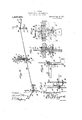
- Figure 1 is a plan view of the chassis of an automobile with the direction-signal of 63 the present.invention applied and moved to one otthe active indicating positions.
- Fig. 2 is a front-elevation of a portion of an automobile with the indicating devices of the present invention applied, and posi- '65 tioned to indicate a turn in one direction.
- Fig. 3 is a rear elevation of the automobile with the invention applied and showing the positionassumed by the rear indicator when movedin the same manner as shown in Figs. 1 and 2.
- Fig. 4 is a perspective view of the indicator structure by itself but as it would appear when assembled upon an automobile.
- Fig. 5 is a horizontal section of the rear portion of the indicator in the position shown in Fig. 3.
- Fig. 6 is a horizontal section-of the front portionof the indicator as seen in Fig. 2-.
- Fig. 7 is a front to rear upright section of the intermediate operating mechanism of the indicator..
- Fig. 8 is an elevation. with some parts inv section. of the structure shown in Fig. 7.
- chassis 1 of an automobile there is shown the chassis 1 of an automobile, and as the showing of the chassis is only for illustrative purposes, and such chassis in its structure has nothing to do with the present invcntion, no description thereof is needful and 9 parts will only bereferred to as may be found necessary in locating the indicating" device. 4
- the indicator structure ot the present in-. vention is best shown in Fig; 4 to which reference isparticularly directed. but features of the invention are shown in all the differ ent figures of the drawing.
- a plate I of suitable shape having an elongated slot or passage therethrongh whicl when the plate is properly located on the floor 2 to which it l screws 5. extends. transgngth oftlic vehicle.
- the bracket 6 has :1 depending web which near the lower end is provided with a suitable passage for a bolt 8, said bolt having at one end a head 9 and at the other end an exteriorly threaded extremity 10 receiving a nut 11.
- the bolt 8 has an axial passage 12 therethrough for a purpose to be described.
- Mounted on the bolt 8 between the bracket 6 and the nut 11 is a gravity member orweight 13 held to the bolt by a set screw 14 tapped through one side of the weight and extending through one side of the bolt 8 to the longitudinal passage 12.
- the set screw 11 serves to secure the weight 13 to the bolt, and the latter is mounted to turn on its longitudinal axis in the bracket 6.
- a finger 15 Extending from the weight 13 on the side of the bolt remote from the greater mass of the weight is a finger 15 provided with a passage or hole 16 therethrough traversed by an angle extremity 17 on one endof an upright bar 18 rising through a passage 19 in the floor 2, said passage coinciding with the slot 4 in the plate 3.
- the bar 18 is of sufficient length to rise an appropriate distance above the plate 3 and is there forked into two opposed branches forming a foot receiving member or rest 20 with the extremities of the forked portion uprising, as shown at 21, to form guards for the foot to prevent side slipping of the foot when applied to the foot rest 20.
- the foot rest 20 rises above-the floor 2 for a short distance, and is readily accessible to the operator who may place his foot upon the foot rest 20 and then by a pressure applied both downwardly and sidewise may cause a rocking movement of the bar 18 causing the weight 13 and bolt 8 then constituting a fulcrum or journal for the weight to rock on the longitudinal axis of the bolt. Downward pressure upon the foot rest then causes the rocking movement of the weight 7 to continue until the heavy end of the weight is raised to about a horizontal position, its
- the rockable weight with the manipulating foot actuated bar 18 constitutes abroken lever, whereby a sidewise movement of the foot rest as it is moved downwardly causes a[ lifting movement of the pendent end of the oveight to the same side of the vertical plane passing through the axis of the bolt as that toward which the foot rest is moved.
- Extending through the passage 12 axially of the bolt 8 is a rod or shaft 22- made long enough to extend from one end of the automobile to the other, either in one piece or through the intermediary of connecting devices, in which latter case the manner of actuating the weight may be varied from that shown in the drawings and may follow the construction shown and described in a companion application, Serial No. 875,337, filed by me on December 3, 1911, under the title automobile direction signal.
- each block 23 and 21 is provided with an axial stem 25 and a set screw .26 and is further provided with an axial dicator 28.
- Each of these indicators is preferably in the form of an arrow and may be made of appropriate sheet metal secured to the respective block 23 or 21 in any appropriate manner, by soldering or brazing, or the block may be appropriately formed to have the arrow otherwise secured to it, so that the block and arrow are effectively in one piece.
- a bracket 29 having angle arms 30 and 31, respectively, the latter terminating in an angle extremity 32, while the arm 30 terminates in an eye 33.
- the extension 25 of the block 23 is journaled in the angle of the bracket 29 and the arm 30 is of a length and so disposed that the eye 33 may be utilized for the attachment of the bracket to the vehicle frame by one of the front spring bolts 31 thereof.
- the arm 31v is uti lized for supporting by its angle end 32 a suitable lamp 35 which may be so constructed and situated as to illuminate the front arrow 27.
- the block 24 has its axial extension 25 journaled in a bracket 36 which in the particular construction shown is provided with an angle arm extension 37 at one end suitably threaded for the reception of nuts 38, so that this threaded extension may be passed through a suitable part 39 of therear portion of the chassis and the nuts 38 applied on opposite sides of this part 39 clamp the bracket firmly in place.
- the other end of the bracket 36 has an upturned extremity 40 designed to carry a tail lamp 41 in position to illuminate the arrow 28.
- the shaft 22 is made ofrelatively small gage, flexible. or more or less elastic, wire, and at the rear end is in the particular-arrangement shown extended through a passage 42 bored through the part 39.
- the presence of obstructing parts of BEST VAiUxELis the machine in the line of the Shanna is shaft.
- The';neutral position of thearrows may be such that the head ends of the arrows pointeither up or down, since it is desirable that the arrows turn upon a horizontal axis or upon horizontal axes. Since it is desir abel that the weight 13. shall normally gravitate to a neutral position, this'weight is arranged pendently and is so secured upon the shaft 22'and the arrows are also so secured upon the shaft that in the pendent position of the weight the arrows assume a. neutral position which is with the heads pointing directly down.
- the head and tail brackets not only serve as journal supports for the corresponding ends of the shaft 22, but also "provide a illuminating elements for the arrows,'so'that they be; come freely visible at "night. these arrows of some distinctive color, such as red, they also are freely visible by daylight.
- the indicating devices, the gravity memberand the connections between the gravity member and, the indicatlng devices all rock in the saniedirection,that is, to i ward the side of the vehicle corresponding to the intendedrhange in course, "while the operating *or causing such rocking has a reciprocahiry movement so related to the rockingmen'imanipulating means for bers *that'the reciproeatory movement i's' converted into a rocking or rotati ⁇ "e n1ovei
- the lateral movement of the pedal is valuable in' throwing the pedal oft center with relation to the axis of rotation of the weight to give the weight an initial impulse in the proper direction, the remainder of the travel of the pedal following as a matter of. course.
- a direction indicator for vehicles comprising a rockable direction indicating means, a roclrable me'mber connected thereto and tending at all 'times to maintain the indicating means in a neutral position, and a reciprocable manipulating member connected to the rockable member for rocking the latter in a direction opposite to the direction of movement of the reciprocating member in causing such rocking movement.
- a direction indicator for vehicles comprising rockable direction indicating means, a rockable gravity member connected thereto to maintain the indicating means in neutral position with the gravity member pendent, and a reciprocable member connected .to the gravity member for causing rocking movements of said gravity member and indicating means by reciprocating movements of the said reciprocating member.
- a direction indicator for vehicles comprising an arrow-like indicating member, a gravity member, a shaft connecting the gravity and indicating members together with 'both members fixed to the shaft, and a reciprocatory actuating member with connections between said reciproeating member and the gravity member for causing the latter to rock from a normally pendent position to an elevated position to carry the indicatingmember with it to indicating position.
- a direction indicator for vehicles comprising an arrow-like indicating means, a normally pendent weight, a shaft connecting the weight and indicating means and consisting of a normally straight rod of a gage and character. to readily bend and operate with the axes of the indicating means and weight out of alineinent, and means for causing rocking movements of the weight, shaft and indicating means to move the latter into operative positions.
- a direction indicator for vehicles comprising rockable indicators adapted to be placed at the opposite ends of the vehicle, connections between the indicators for causing them to move together to different indicating positions, a normally pendent rockable weight carried by the connections for holding the indicators in a neutral position, and a reciprocatory manipulating member having pivotal connections joined to the connections between the indicators for causing rocking movements of said indicators and weight by reciprocatory movements of the n'ianipulating member.
- a direction indicator for vehicles comprising indicators adapted to be placed at opposite ends of the vehicles and each movable on a substantially horizontal axis from a normally intermediate neutral position to substantially horizontal positions of direction indication, a connecting rod between the indicators of a gage and character to assume a: normally straight position and readily bend to operate with the'axes of the indicating means out of alinement, gravity means connected to the rod and having a normal tendency to hold the indicators in the neutral position, and reciprocable means for rocking the rod to carry the indicators to different indicating positions by' reciprocatory movements of the' mani pulating means.
- a direction indicator for vehicles comprising arrow-lik'e indicating members adapted to move about a substantially horizontal axis from a normal up and down neutral position to horizontal active positions, rod connections between the indicators of. flexible material and of a gage to readily conform-to out of alinement positions With respect to the axes of the indicators and to operate in such position, a normally pendent weight carried by the rod connections for holding the indicators in the neutral position, and a reciprocatory manipulating member for imparting rocking movements to the rod indicators and weight by reciprocatory movements of the manipulating member.
- a direction indicator for vehicles comprising a shaft of a length to reach from one cud of the vehicle to the other.
- arrow-like indicators mounted on the ends of the shaft and fast thereto.
- a normally pendent weight made fast to the shaft at an intermediate point thereof. and means for imparting rocking movements to the weight, shaft and indicators comprising a reciprocable member having one end accessible to an operator and the other end pivotally connected to'tlie weight, and a guide for said reciprocable' member for permitting it to follow the rocking movements of the weight to which it is connected.
- a direction indicator for vehicles comprising ashaft of a length to extend from pivotal connection to the Weight, and a guiding member whereby said pedal member maybe reciprocated and rocked.
- a direction indicator for vehicles comprising a rock shaft of a length to extend from one end of the vehicle to the other, indicators fast to the shaft at the ends thereof, journal supports for the ends of the shaft, a normally pendent Weight fast to the shaft at an intermediate point thereof, a journal support for the weight permitting rocking movements of said weight, means for securing the journal support w; it to the vehicle, a reciprocable bar z ving one end pivoted to the weight and at the other end tern'linating in a foot-receiving member adapted to be located within reach of an operator, and a guide plate for the reciprocable bar for permitting limited rock- .ing movements reciprocatory movements, whereby the bar maybe moved laterally with respect to the axis of movement of the Weight to determine ithe direction or rocking movement of said 5 weight.
- a direction indicating means for vehicles comprising a rock shaft of a length to reach fromlone end of the vehicle to the other, arrow-like indicators one fast to each of the' thereof in addition to its end of the rock shaft, brackets at each end of the rock shaft provided with journal bearings therefor and each bracket having means for its attachment to the vehicle, a journal member fast to the. rock shaft at an intermediate point thereof, a normally pendent Weight fast to the journal member and provided with an extension to that side of the axis of the journal memben remote from the body of the weight, a journal support for the intermediate journal member and adapted to be secured to the under side of'the floor of that portion of the vehicle occupied by the operator, at laterally slotted plate adapted to be secured to.
- amanipulating member comprising a bar extending through the slotted portion of the plate with one end pivotally connected to the extension of the weight, and at the other end expanded to form a foot-recelving member or pedal.
Landscapes
- Engineering & Computer Science (AREA)
- Mechanical Engineering (AREA)
- Lighting Device Outwards From Vehicle And Optical Signal (AREA)
Description
E. J. BRYAN.
DIRECTION SIGNAL FOR AUTOMOBILES.
APPLICATION map DEC. 12. 1914.
1,237,991 Patented Aug. 21,1917.
2 SHEETS-SHEET I WITNESSES INVENTOR,
E. J. BRYAN.
DlRECTlON SIGNAL FQR AUTOMOBILES.
APPLICATION FILED DEC. 12. 1914.
' Patented Aug. 21, 1917.
2 SHEETS-SHEET 2.
ATTO N EY EDGAR J; BRYAN, F RIVERSIDE,
CALIFORNIA, ASSIGNOR OF ONE-HALFTO WILLIAM T. THOMPSON, 0F RIVERSIDE, CALIFORNIA;
To ZZ whom it may concern:
lle it known that LEDGAR J. BRYAN, a. citizen of-the-United States, residing at Riverside, in the county of Riverside and State of California, have invented. a new and useful Direction-Signal for Automobiles, of which the following is a specification.
This invention has reference todirection signalsv for automobiles and other vehicles,
and its object is to provide an etlieient and easily installed device for the purpose which at thesame time possesses the advantages of extreme simplicity and low cost of manutac-- tu rie.
In accordance with the present invention direction indicating devio s preferably in the form of arrows are located at the front and rear of the vehicle, and are mounted on the ends of and connected together by -a wire-like rod which may be made of elastic steel of relatively small gage, so that aline merit of the axes of the arrows is not necessary' and consequently 'no particular care need betaken in the installation of the device, to secure any accuracy of alinemc nt. Thearrow-carrying shaft is mounted at the ends in journal brackets so arranged as to 'be readily secured to the vehicle'and may also be arranged to support lamps by means of which the arrows are illuminated at night. The arrow-carrying shaft is provided at a point convenient to the operator witha gravity structure, whereby the shaft may be rocked in one direction or the other,
ormay be allowedto rest in a normally neutal position. I made that the arrowsare automatically returned to the neutral position when displaced therefrom and the gravity device is 40 so arranged as to beread ly moved by the foot of the operator to the indicating positions, the direction of movement of the foot ofthe operatorconforming to the deslred direction-indicating position of the arrows.
The invention'will be-best understood from a consideration of the following detailed description, taken in connection with theaccompanyin-g drawings forming a part ofthisspecification, with the further nnder- 0 standing that while the drawings show a practical im-m of theinvention, thelat'tcr is not confined to any strict conformity \\|l',ll, I
the'showing of tlie"dra\\'ings, but may be changed and mod1fied so long as such ehanges and modifications mark no material Specification of Letters Patent.
Application filed December 12 1914. Serial No. 876,897.
The gravity structure is sov DIRECTION-SIGNAL FOR AUTOMOBILES. I
Patented An 21, 1 917.
in vention. I
In the drawings Figure 1 is a plan view of the chassis of an automobile with the direction-signal of 63 the present.invention applied and moved to one otthe active indicating positions.
Fig. 2 is a front-elevation of a portion of an automobile with the indicating devices of the present invention applied, and posi- '65 tioned to indicate a turn in one direction.
Fig. 3 is a rear elevation of the automobile with the invention applied and showing the positionassumed by the rear indicator when movedin the same manner as shown in Figs. 1 and 2.
Fig. 4 is a perspective view of the indicator structure by itself but as it would appear when assembled upon an automobile.
Fig. 5 is a horizontal section of the rear portion of the indicator in the position shown in Fig. 3.
Fig. 6 is a horizontal section-of the front portionof the indicator as seen in Fig. 2-.
Fig. 7 is a front to rear upright section of the intermediate operating mechanism of the indicator..
Fig. 8 is an elevation. with some parts inv section. of the structure shown in Fig. 7.
Referring to the drawings there is shown the chassis 1 of an automobile, and as the showing of the chassis is only for illustrative purposes, and such chassis in its structure has nothing to do with the present invcntion, no description thereof is needful and 9 parts will only bereferred to as may be found necessary in locating the indicating" device. 4
The indicator structure ot" the present in-. vention is best shown in Fig; 4 to which reference isparticularly directed. but features of the invention are shown in all the differ ent figures of the drawing.
i The operators c mipartmcnt-of an automobile is provided with a flooring indicated at 2 in Figs. 1, 7 and 8. Applied to the up-- per surface of the tloor 2 is a plate I) of suitable shape having an elongated slot or passage therethrongh whicl when the plate is properly located on the floor 2 to which it l screws 5. extends. transgngth oftlic vehicle. At-
departure from the salient features of the .tached' to the under surface of the floor 2 is an angle bracket (3, the means of attachment comprising screws or bolts 7 traversing the plate 3 and the flooring 2 and tapped into the bracket 6. Of course, it will be understood that any suitable means of securing the parts described to the flooring 2 may be employed, whether the securing means be such as described or be of other form.
The bracket 6 has :1 depending web which near the lower end is provided with a suitable passage for a bolt 8, said bolt having at one end a head 9 and at the other end an exteriorly threaded extremity 10 receiving a nut 11. The bolt 8 has an axial passage 12 therethrough for a purpose to be described. Mounted on the bolt 8 between the bracket 6 and the nut 11 is a gravity member orweight 13 held to the bolt by a set screw 14 tapped through one side of the weight and extending through one side of the bolt 8 to the longitudinal passage 12. The set screw 11 serves to secure the weight 13 to the bolt, and the latter is mounted to turn on its longitudinal axis in the bracket 6. Extending from the weight 13 on the side of the bolt remote from the greater mass of the weight is a finger 15 provided with a passage or hole 16 therethrough traversed by an angle extremity 17 on one endof an upright bar 18 rising through a passage 19 in the floor 2, said passage coinciding with the slot 4 in the plate 3. The bar 18 is of sufficient length to rise an appropriate distance above the plate 3 and is there forked into two opposed branches forming a foot receiving member or rest 20 with the extremities of the forked portion uprising, as shown at 21, to form guards for the foot to prevent side slipping of the foot when applied to the foot rest 20.
If it be assumed that the device so far described is mounted on an, automobile the foot rest 20 rises above-the floor 2 for a short distance, and is readily accessible to the operator who may place his foot upon the foot rest 20 and then by a pressure applied both downwardly and sidewise may cause a rocking movement of the bar 18 causing the weight 13 and bolt 8 then constituting a fulcrum or journal for the weight to rock on the longitudinal axis of the bolt. Downward pressure upon the foot rest then causes the rocking movement of the weight 7 to continue until the heavy end of the weight is raised to about a horizontal position, its
ordinary'position being downward or pendent. The rockable weight with the manipulating foot actuated bar 18 constitutes abroken lever, whereby a sidewise movement of the foot rest as it is moved downwardly causes a[ lifting movement of the pendent end of the oveight to the same side of the vertical plane passing through the axis of the bolt as that toward which the foot rest is moved.
Extending through the passage 12 axially of the bolt 8 is a rod or shaft 22- made long enough to extend from one end of the automobile to the other, either in one piece or through the intermediary of connecting devices, in which latter case the manner of actuating the weight may be varied from that shown in the drawings and may follow the construction shown and described in a companion application, Serial No. 875,337, filed by me on December 3, 1911, under the title automobile direction signal.
Considering the shaft 22 as a one-piece shaft, it extends oppositely from the bolt 8 to the corresponding ends of the automobile and at each end carries a block 23, 24:, respectively. Each block 23 and 21 is provided with an axial stem 25 and a set screw .26 and is further provided with an axial dicator 28. Each of these indicators is preferably in the form of an arrow and may be made of appropriate sheet metal secured to the respective block 23 or 21 in any appropriate manner, by soldering or brazing, or the block may be appropriately formed to have the arrow otherwise secured to it, so that the block and arrow are effectively in one piece.
At the front of the vehicle there is provided a bracket 29 having angle arms 30 and 31, respectively, the latter terminating in an angle extremity 32, while the arm 30 terminates in an eye 33. The extension 25 of the block 23 is journaled in the angle of the bracket 29 and the arm 30 is of a length and so disposed that the eye 33 may be utilized for the attachment of the bracket to the vehicle frame by one of the front spring bolts 31 thereof. The arm 31v is uti lized for supporting by its angle end 32 a suitable lamp 35 which may be so constructed and situated as to illuminate the front arrow 27. At the rear end of the shaft 22 the block 24 has its axial extension 25 journaled in a bracket 36 which in the particular construction shown is provided with an angle arm extension 37 at one end suitably threaded for the reception of nuts 38, so that this threaded extension may be passed through a suitable part 39 of therear portion of the chassis and the nuts 38 applied on opposite sides of this part 39 clamp the bracket firmly in place. The other end of the bracket 36 has an upturned extremity 40 designed to carry a tail lamp 41 in position to illuminate the arrow 28.
The shaft 22 is made ofrelatively small gage, flexible. or more or less elastic, wire, and at the rear end is in the particular-arrangement shown extended through a passage 42 bored through the part 39. However, the presence of obstructing parts of BEST VAiUxELis the machine in the line of the Shanna is shaft. By the use of the front and rear journal brackets 29 and 36 the front-and rear indicating arrows 27 and 28 are properly supported and heldin the desired relation to the vehicle; The axes of these two arrows may or may not be in alinement,
'and they may or may not .he in alinement' with the axis of the bolt 8, so that it is quite easy to apply the structure of the present invention to an automobile," since there is little occasion for fitting and under some circumstances no fitting at all is re quired, such fitting oftentimes being avoided because of they employmentof the light, small gage flexible shaft in the form of a wire or small rod of material sufliciently elasticto permitthe desired degree of bendin g without set.
The';neutral position of thearrows may be such that the head ends of the arrows pointeither up or down, since it is desirable that the arrows turn upon a horizontal axis or upon horizontal axes. Since it is desir abel that the weight 13. shall normally gravitate to a neutral position, this'weight is arranged pendently and is so secured upon the shaft 22'and the arrows are also so secured upon the shaft that in the pendent position of the weight the arrows assume a. neutral position which is with the heads pointing directly down.
Now if the operator desires to divert the course of travel to the right orleft, he places his foot upon the'foot rest 20, which because of its purpose may be termed a pedal, and by applying. pressure to this footrest or pedal in a downward direction with a tendency toward the'side of the ma;- chine conforming to the intended direction of'turning, the heads of'the arrows are at Once'sn'ung toward the side of the vehicle,
wtiindieating the intended direction of diver sion of course. .Under' these circumstances the weight is moved to approximately horizontal position and the arrows are likewise moved to an approximately horizontal po 7 ..-sition, thus apprising those toward whom thevehicle is approaching and those foltendsto turn in the direction indicated by the -arro\\'s. For tlns purpose it ls not neceswhile the .instant, the foot is removed from the pedal 20 the parts automatically return to the central or neutral position. There IS ready means for sustaining m'ent. I H i pedal s directly connected to the weight sary for the/operator to use lns hands at all,
con I, V
return of the parts becomes entirely automatic,'and without attention at all in manner on the part of the operator.
The head and tail brackets not only serve as journal supports for the corresponding ends of the shaft 22, but also "provide a illuminating elements for the arrows,'so'that they be; come freely visible at "night. these arrows of some distinctive color, such as red, they also are freely visible by daylight.
-By the use ofa weight or gravit'y mein- J her for giving); to thdmdiciitors normal constraint toward the neut1'al'p,o sition, the whole device isvrendered ve'ry e'fiec'tivefand: at the same time exceedingly simple both in construction and operation. Moreover, the employment of the gravity makes the device particularlyreliable since there are no parts to'break or get out of order and accumulations of dirt or other deleterious matter to which structurescar- By making a member ried upon automobiles, and especially ex-i posed structures, are liable, do not inter: fere with the positive operation of the de-,
vice. The operatorltherefore .hasthe constant assurancethat the device isinoperative condition, and will always respond in the, proper manner to impulses purposely imparted to it. Under all the gravity device holds the --indicators' strictly to the general neutral position and; no shocks or jarsto which the vehicle'may be subjected are likely to cause any operation of the indicators to the active position. Even should such excessive movement occur,
it will be but momentary, so that it would not impart to an observer any information which mi ,g'ht be" taken as an indication 'of an intended change in course of .the'a'utomobile.-
I conditions of 'use lVith the structure of thep resent i s- 1:
tion the indicating devices, the gravity memberand the connections between the gravity member and, the indicatlng devices all rock in the saniedirection,that is, to i ward the side of the vehicle corresponding to the intendedrhange in course, "while the operating *or causing such rocking has a reciprocahiry movement so related to the rockingmen'imanipulating means for bers *that'the reciproeatory movement i's' converted into a rocking or rotati\"e n1ovei For purposes of slmphcity'the and is so ariaiig'edthat tendency of' 'the' i BEST AVAlLABLE COP rock it in the proper direction. The lateral movement of the pedal is valuable in' throwing the pedal oft center with relation to the axis of rotation of the weight to give the weight an initial impulse in the proper direction, the remainder of the travel of the pedal following as a matter of. course.
' What is claimed is 1. A direction indicator for vehicles comprising a rockable direction indicating means, a roclrable me'mber connected thereto and tending at all 'times to maintain the indicating means in a neutral position, and a reciprocable manipulating member connected to the rockable member for rocking the latter in a direction opposite to the direction of movement of the reciprocating member in causing such rocking movement.
2. A direction indicator for vehicles, comprising rockable direction indicating means, a rockable gravity member connected thereto to maintain the indicating means in neutral position with the gravity member pendent, and a reciprocable member connected .to the gravity member for causing rocking movements of said gravity member and indicating means by reciprocating movements of the said reciprocating member.
A direction indicator for vehicles comprising an arrow-like indicating member, a gravity member, a shaft connecting the gravity and indicating members together with 'both members fixed to the shaft, and a reciprocatory actuating member with connections between said reciproeating member and the gravity member for causing the latter to rock from a normally pendent position to an elevated position to carry the indicatingmember with it to indicating position.
4. A direction indicator for vehicles comprising an arrow-like indicating means, a normally pendent weight, a shaft connecting the weight and indicating means and consisting of a normally straight rod of a gage and character. to readily bend and operate with the axes of the indicating means and weight out of alineinent, and means for causing rocking movements of the weight, shaft and indicating means to move the latter into operative positions.
5. A direction indicator for vehicles comprising rockable indicators adapted to be placed at the opposite ends of the vehicle, connections between the indicators for causing them to move together to different indicating positions, a normally pendent rockable weight carried by the connections for holding the indicators in a neutral position, and a reciprocatory manipulating member having pivotal connections joined to the connections between the indicators for causing rocking movements of said indicators and weight by reciprocatory movements of the n'ianipulating member.
(3. A direction indicator for vehicles comprising indicators adapted to be placed at opposite ends of the vehicles and each movable on a substantially horizontal axis from a normally intermediate neutral position to substantially horizontal positions of direction indication, a connecting rod between the indicators of a gage and character to assume a: normally straight position and readily bend to operate with the'axes of the indicating means out of alinement, gravity means connected to the rod and having a normal tendency to hold the indicators in the neutral position, and reciprocable means for rocking the rod to carry the indicators to different indicating positions by' reciprocatory movements of the' mani pulating means. e
7. A direction indicator for vehicles comprising arrow-lik'e indicating members adapted to move about a substantially horizontal axis from a normal up and down neutral position to horizontal active positions, rod connections between the indicators of. flexible material and of a gage to readily conform-to out of alinement positions With respect to the axes of the indicators and to operate in such position, a normally pendent weight carried by the rod connections for holding the indicators in the neutral position, and a reciprocatory manipulating member for imparting rocking movements to the rod indicators and weight by reciprocatory movements of the manipulating member.
8. A direction indicator for vehicles comprising a shaft of a length to reach from one cud of the vehicle to the other. arrow-like indicators mounted on the ends of the shaft and fast thereto. a normally pendent weight made fast to the shaft at an intermediate point thereof. and means for imparting rocking movements to the weight, shaft and indicators comprising a reciprocable member having one end accessible to an operator and the other end pivotally connected to'tlie weight, and a guide for said reciprocable' member for permitting it to follow the rocking movements of the weight to which it is connected.
9. A direction indicator for vehicles, comprising ashaft of a length to extend from pivotal connection to the Weight, and a guiding member whereby said pedal member maybe reciprocated and rocked.
10. A direction indicator for vehicles, comprising a rock shaft of a length to extend from one end of the vehicle to the other, indicators fast to the shaft at the ends thereof, journal supports for the ends of the shaft, a normally pendent Weight fast to the shaft at an intermediate point thereof, a journal support for the weight permitting rocking movements of said weight, means for securing the journal support w; it to the vehicle, a reciprocable bar z ving one end pivoted to the weight and at the other end tern'linating in a foot-receiving member adapted to be located within reach of an operator, and a guide plate for the reciprocable bar for permitting limited rock- .ing movements reciprocatory movements, whereby the bar maybe moved laterally with respect to the axis of movement of the Weight to determine ithe direction or rocking movement of said 5 weight.
11. A direction indicating means for vehicles comprising a rock shaft of a length to reach fromlone end of the vehicle to the other, arrow-like indicators one fast to each of the' thereof in addition to its end of the rock shaft, brackets at each end of the rock shaft provided with journal bearings therefor and each bracket having means for its attachment to the vehicle, a journal member fast to the. rock shaft at an intermediate point thereof, a normally pendent Weight fast to the journal member and provided with an extension to that side of the axis of the journal memben remote from the body of the weight, a journal support for the intermediate journal member and adapted to be secured to the under side of'the floor of that portion of the vehicle occupied by the operator, at laterally slotted plate adapted to be secured to. the floor of the vehicle in the compartment occupied by the operator, and amanipulating member comprising a bar extending through the slotted portion of the plate with one end pivotally connected to the extension of the weight, and at the other end expanded to form a foot-recelving member or pedal.
In testimony, that I claim the foregoing as my own, I have hereto aifixed my signature in the presence of two witnesses.
EDGAR J. BRYAN. Witnesses t C. P. HEBERT, C. E. CARROLL.
Priority Applications (1)
| Application Number | Priority Date | Filing Date | Title |
|---|---|---|---|
| US87689714A US1237291A (en) | 1914-12-12 | 1914-12-12 | Direction-signal for automobiles. |
Applications Claiming Priority (1)
| Application Number | Priority Date | Filing Date | Title |
|---|---|---|---|
| US87689714A US1237291A (en) | 1914-12-12 | 1914-12-12 | Direction-signal for automobiles. |
Publications (1)
| Publication Number | Publication Date |
|---|---|
| US1237291A true US1237291A (en) | 1917-08-21 |
Family
ID=3305110
Family Applications (1)
| Application Number | Title | Priority Date | Filing Date |
|---|---|---|---|
| US87689714A Expired - Lifetime US1237291A (en) | 1914-12-12 | 1914-12-12 | Direction-signal for automobiles. |
Country Status (1)
| Country | Link |
|---|---|
| US (1) | US1237291A (en) |
-
1914
- 1914-12-12 US US87689714A patent/US1237291A/en not_active Expired - Lifetime
Similar Documents
| Publication | Publication Date | Title |
|---|---|---|
| US1237291A (en) | Direction-signal for automobiles. | |
| US1389717A (en) | Automobile attachment | |
| US1234831A (en) | Direction-indicator for automobiles. | |
| US1347334A (en) | Direction-indicator for bicycles | |
| US1337849A (en) | Headlight-controlling mechanism | |
| US1139078A (en) | Speed-changing mechanism. | |
| US1536966A (en) | Brake extension | |
| US1307927A (en) | Cibctjit-closeb | |
| US2512817A (en) | Rotatable head lamp assembly | |
| US1687164A (en) | Automobile direction signal | |
| US1458023A (en) | Signal for vehicles | |
| US1293841A (en) | Signaling device. | |
| US1493704A (en) | Movable headlight | |
| US1428260A (en) | Automobile signal | |
| US1400601A (en) | Direction-indicator for vehicles | |
| US1341593A (en) | Dirigible light | |
| US1475513A (en) | Signal | |
| US1296065A (en) | Direction-indicator for autovehicles. | |
| US1866411A (en) | Indicating signal device | |
| US1167821A (en) | Signal for motor-cars. | |
| US1182618A (en) | Signal. | |
| US1316821A (en) | Planoobaph co | |
| US1430489A (en) | Signal machine | |
| US1397798A (en) | Safety foot-throttle for automobiles | |
| US1487537A (en) | Direction indicator |