US1237287A - Toy railroad. - Google Patents
Toy railroad. Download PDFInfo
- Publication number
- US1237287A US1237287A US8454316A US8454316A US1237287A US 1237287 A US1237287 A US 1237287A US 8454316 A US8454316 A US 8454316A US 8454316 A US8454316 A US 8454316A US 1237287 A US1237287 A US 1237287A
- Authority
- US
- United States
- Prior art keywords
- rail
- train
- switch
- lamp
- circuit
- Prior art date
- Legal status (The legal status is an assumption and is not a legal conclusion. Google has not performed a legal analysis and makes no representation as to the accuracy of the status listed.)
- Expired - Lifetime
Links
- QSHDDOUJBYECFT-UHFFFAOYSA-N mercury Chemical compound [Hg] QSHDDOUJBYECFT-UHFFFAOYSA-N 0.000 description 2
- 229910052753 mercury Inorganic materials 0.000 description 2
- 230000004308 accommodation Effects 0.000 description 1
- 238000001816 cooling Methods 0.000 description 1
- 230000000881 depressing effect Effects 0.000 description 1
- 238000010586 diagram Methods 0.000 description 1
- 230000005611 electricity Effects 0.000 description 1
- 230000004048 modification Effects 0.000 description 1
- 238000012986 modification Methods 0.000 description 1
- 230000011664 signaling Effects 0.000 description 1
Images
Classifications
-
- A—HUMAN NECESSITIES
- A63—SPORTS; GAMES; AMUSEMENTS
- A63H—TOYS, e.g. TOPS, DOLLS, HOOPS OR BUILDING BLOCKS
- A63H19/00—Model railways
- A63H19/24—Electric toy railways; Systems therefor
Definitions
- the train restarts and the signal is extinguished.
- a green signal which may be displayed continually during the running of the train is extinguished when the train comes to a stop and the red sigal shows.
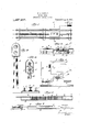
- Figure 1 is a plan of'an electric toy railway embodying my invention
- Fig. 2 a cross section on line 2-2 Fig. 1;
- Fig. 3 a longitudinal section through the switch and adjoining parts;
- Fig. 4 a section through the upper part of the signal tower
- Fig. 5 a' detail of the open work section of the Contact rail
- Fig. 6 a wiring diagram and of the The device comprises a track 1, a contact rail or third rail 2, and a battery or other source of electricity 3, adapted toy send a current therethrough.
- the contact rail '2 isnv provided with a tubular head 4, within which" a wooden or.other insulating rod 5 is housed.
- rail 2 is cut away at intervals (Figs. l and 5) so that rod 5 is here intermittently exposed and covered up.
- the shoe 6 on the toy train will alternately receive and'lose current, with the result that the speed of the train is gradually slackened.
- head ⁇ 4 may be cutaway at a single point only ⁇ (Fig. 7 in which case, there is of course, but a single exposure of the insulating rod.
- a gap oropening for the accommodation of an insulating platform 7, carrying a vertically 'movable switch plate or member 8 which is adapted to form an insulated section of the third rail. From plate 8, depend a pair of insulated pins 9 passing through corresponding apertures of platform 7 ,and operatively engaging one of a pair of contact springs 10 secured to the lower side of the platform.
- a toy railroad comprising a third rail, having an insulated section, an insulated member at a' distance beyond said insulated section, a switch controlled by said member, and a lamp. in circuit with the switch.
- a toy railroad comprising a train shoe, a third rail, an insulated member adapted to be engaged by the shoe, a switch controlled by said member, a lamp in circuit with the switch, and a thermostat in proximity to the lamp and in circuit with the insulated member.
- a toy railroad comprising a train shoe
- a third rail an insulated member adapted to be'engaged by the shoe, a switch controlled by said member, a first lamp in circuit with the switch, and a second lamp in circuit with the third rail.
- a third rail an insulated member adapted to be engaged by the shoe, a switch controlled by said member, a first lam in circuit with the switch, a thermostat 1n proximity to thelamp and in circuit with the insulated member, and a' second lamp in cir cuit with the third rail.
- a third rail having a cut away tubular head, and an insulating.
- an insulated .member arranged at a distance from the out away portion of the head, a switch controlled by said member, -a lamp in circuit with the switch, and. a thermostat in proximity to the lamp and in circuit with the insulated member.
Landscapes
- Toys (AREA)
Description
W. J. BOEMPEB.
TOY RAILROAD.
APPLICATION FILED MAII. I6. 1914s.
- Patented Aug. 21,1917.v
IlIIIIlIIHgflllllllllllllllilllll s'rarns ra nr braio.
WILLIE J. Boni/Irisa, or NEW YORK, N. Y.
v'roY RAILROAD.
Specification of Letters Patent.
Patented Aug. 21, 1917.
' Application filed March 16, 1916. Serial No. 84,543.
To all whom t may concern:
Be it known'that I, .'WILLIE J. BoEMrnR,
. a citizen of the United States, and a resident N signal is displayed and after the lapse of Fig. 7 a detail of a modification contact rail.
some time, the train restarts and the signal is extinguished. A green signal which may be displayed continually during the running of the train is extinguished when the train comes to a stop and the red sigal shows.
In the accompanying drawing: Figure 1 is a plan of'an electric toy railway embodying my invention;
. Fig. 2 a cross section on line 2-2 Fig. 1; Fig. 3 a longitudinal section through the switch and adjoining parts;
Fig. 4 a section through the upper part of the signal tower; Y v
Fig. 5 a' detail of the open work section of the Contact rail;
Fig. 6 a wiring diagram and of the The device comprises a track 1, a contact rail or third rail 2, and a battery or other source of electricity 3, adapted toy send a current therethrough. The contact rail '2 isnv provided with a tubular head 4, within which" a wooden or.other insulating rod 5 is housed. Near the station (or assumed sta-- tion), rail 2 is cut away at intervals (Figs. l and 5) so that rod 5 is here intermittently exposed and covered up. In this way, the shoe 6 on the toy train will alternately receive and'lose current, with the result that the speed of the train is gradually slackened. If desired, however, head`4 may be cutaway at a single point only` (Fig. 7 in which case, there is of course, but a single exposure of the insulating rod.
Some distance beyond the slowing up section of rail 2, there is formed within' the same, a gap oropening for the accommodation of an insulating platform 7, carrying a vertically 'movable switch plate or member 8 which is adapted to form an insulated section of the third rail. From plate 8, depend a pair of insulated pins 9 passing through corresponding apertures of platform 7 ,and operatively engaging one of a pair of contact springs 10 secured to the lower side of the platform. When the slowed down train -has advanced to such a point, that its shoe 6,
comes into engagement with the insulated plate 8, the current will be cut off, and the train come to a full stop. At the same time, the shoe by depressing plate 8, will close switch 10, and thus light a red dangerl signal lamp 11 located within a signaling tower 12, vthe current flowingl as follows: switch 10, wire 13, lamp 11,' wire 14, grounded rail 1, battery 3, rail 2, wire 15 back to the switch. Means actuated by the heat emitted from lamp 11 are provided which, upon the lapse of some time, will charge plate 8 with current and thus re-start the train. For this purpose, there is mounted l within tower 12, in proximity to lamp 11, a thermostat, or -similar device 16 having a pair of poles one of which is immersed in the mercury while the other is normally raised above the level thereof. Whenlight 1]. has been burning for sometime, the heat evolved will cause the mercury to rise and tol contact with the raised pole, so as to close a circuit which will send current into plate 8, the current trayeling as follows: thermostat 16, wire 17, plate 8, shoe 6, motor on car rail l, battery 3, rail 2, wire 18, back to the thermostat. Ilf this way, the train will again receive current,'which will carry it off plate 8, and forward along the track, until it meets n second station where the mechanism described may be duplicated. As soon as the train has cleared plate 8, switch 10 will be opened so that light 11 is extinguished.
This will cause a gradual cooling off of thermostat 16, whereby th'e circuit will here bc againbroken, and the current be cut off from plate 8.
It is preferred to install into tower 12, a. green lor safety light 19 which receives continuous -current while the train is traveling, by meansA of wires 20, 21. This current flows through the. following circuit: rail 1,
battery 3, third rail 2, wire 15,'upper mem-- vber of switch 10, contact 21, wire 21, lamp 19, and back to rail 1 through wire 20. 'As soon 'as the train has arrived over the insulated plate 8, the circuit is broken at 21a, so that the light is extinguished, 'to be rekindled as soon as the train has passed the plate.
l. A toy railroad comprising a third rail, having an insulated section, an insulated member at a' distance beyond said insulated section, a switch controlled by said member, and a lamp. in circuit with the switch.
, 2. A toy railroad comprising a train shoe, a third rail, an insulated member adapted to be engaged by the shoe, a switch controlled by said member, a lamp in circuit with the switch, and a thermostat in proximity to the lamp and in circuit with the insulated member.
3. A toy railroad comprising a train shoe,
a third rail, an insulated member adapted to be'engaged by the shoe, a switch controlled by said member, a first lamp in circuit with the switch, and a second lamp in circuit with the third rail.
4. `A toy railroad comprising a train shoe,
a third rail, an insulated member adapted to be engaged by the shoe, a switch controlled by said member, a first lam in circuit with the switch, a thermostat 1n proximity to thelamp and in circuit with the insulated member, and a' second lamp in cir cuit with the third rail.
5. In a toy railroad, a third rail having a cut away tubular head, and an insulating.
head, an insulated .member arranged at a distance from the out away portion of the head, a switch controlled by said member, -a lamp in circuit with the switch, and. a thermostat in proximity to the lamp and in circuit with the insulated member.
WILlLlE J.- BUEMPER.
Priority Applications (1)
| Application Number | Priority Date | Filing Date | Title |
|---|---|---|---|
| US8454316A US1237287A (en) | 1916-03-16 | 1916-03-16 | Toy railroad. |
Applications Claiming Priority (1)
| Application Number | Priority Date | Filing Date | Title |
|---|---|---|---|
| US8454316A US1237287A (en) | 1916-03-16 | 1916-03-16 | Toy railroad. |
Publications (1)
| Publication Number | Publication Date |
|---|---|
| US1237287A true US1237287A (en) | 1917-08-21 |
Family
ID=3305106
Family Applications (1)
| Application Number | Title | Priority Date | Filing Date |
|---|---|---|---|
| US8454316A Expired - Lifetime US1237287A (en) | 1916-03-16 | 1916-03-16 | Toy railroad. |
Country Status (1)
| Country | Link |
|---|---|
| US (1) | US1237287A (en) |
Cited By (6)
| Publication number | Priority date | Publication date | Assignee | Title |
|---|---|---|---|---|
| US2486299A (en) * | 1948-10-16 | 1949-10-25 | Edwin P Lepper | Toy signal device |
| US2951452A (en) * | 1957-04-05 | 1960-09-06 | Gen Railway Signal Co | Remote control system for a trimming locomotive |
| DE1189424B (en) * | 1957-12-27 | 1965-03-18 | Maerklin & Cie Gmbh Geb | Contactor built into a section of a toy railroad track |
| US3206744A (en) * | 1963-06-11 | 1965-09-14 | Paul E Nelson | Semaphore light |
| US3214038A (en) * | 1962-03-05 | 1965-10-26 | Gen Signal Corp | Control system for railway vehicles |
| US20020195595A1 (en) * | 2000-03-30 | 2002-12-26 | Shepherd John D. | Railing assembly |
-
1916
- 1916-03-16 US US8454316A patent/US1237287A/en not_active Expired - Lifetime
Cited By (6)
| Publication number | Priority date | Publication date | Assignee | Title |
|---|---|---|---|---|
| US2486299A (en) * | 1948-10-16 | 1949-10-25 | Edwin P Lepper | Toy signal device |
| US2951452A (en) * | 1957-04-05 | 1960-09-06 | Gen Railway Signal Co | Remote control system for a trimming locomotive |
| DE1189424B (en) * | 1957-12-27 | 1965-03-18 | Maerklin & Cie Gmbh Geb | Contactor built into a section of a toy railroad track |
| US3214038A (en) * | 1962-03-05 | 1965-10-26 | Gen Signal Corp | Control system for railway vehicles |
| US3206744A (en) * | 1963-06-11 | 1965-09-14 | Paul E Nelson | Semaphore light |
| US20020195595A1 (en) * | 2000-03-30 | 2002-12-26 | Shepherd John D. | Railing assembly |
Similar Documents
| Publication | Publication Date | Title |
|---|---|---|
| US1237287A (en) | Toy railroad. | |
| US441030A (en) | Island | |
| US1657816A (en) | Lighting system for conveyances | |
| US1696534A (en) | Toy electric-railway control device | |
| US898216A (en) | Electric-railway conduit. | |
| US396749A (en) | William p | |
| US250764A (en) | Electric lighting apparatus for railway-trains | |
| US1478100A (en) | Wanda a | |
| US1181543A (en) | Safety flash-light for elevators. | |
| US1914715A (en) | Electrical switch | |
| US1321635A (en) | Electric railway-signal | |
| US735416A (en) | Electric signaling apparatus. | |
| US1098112A (en) | Signaling system for electric railways. | |
| US756523A (en) | Automatic power cut-out for electric railways. | |
| US889482A (en) | Electric signaling system. | |
| US2414079A (en) | Railroad track switch position indicator system and car actuated circuit controllertherefor | |
| US1141953A (en) | Electric train control. | |
| US1431051A (en) | Railroad-crossing signal | |
| US1066380A (en) | Electric signal system. | |
| US788872A (en) | Automatic electric-light connection for automatic railway block-signals. | |
| US432657A (en) | timmis | |
| US1201494A (en) | Railway signal system. | |
| US613708A (en) | Electric railway | |
| US1190297A (en) | Lighting system for electrically-propelled vehicles. | |
| US1695678A (en) | Railway-traffic-controlling apparatus |