US1237262A - Take-down device. - Google Patents
Take-down device. Download PDFInfo
- Publication number
- US1237262A US1237262A US87107814A US1914871078A US1237262A US 1237262 A US1237262 A US 1237262A US 87107814 A US87107814 A US 87107814A US 1914871078 A US1914871078 A US 1914871078A US 1237262 A US1237262 A US 1237262A
- Authority
- US
- United States
- Prior art keywords
- cable
- trolley
- support
- cylinder
- fixed point
- Prior art date
- Legal status (The legal status is an assumption and is not a legal conclusion. Google has not performed a legal analysis and makes no representation as to the accuracy of the status listed.)
- Expired - Lifetime
Links
Images

Classifications
-
- C—CHEMISTRY; METALLURGY
- C03—GLASS; MINERAL OR SLAG WOOL
- C03B—MANUFACTURE, SHAPING, OR SUPPLEMENTARY PROCESSES
- C03B15/00—Drawing glass upwardly from the melt
- C03B15/14—Drawing tubes, cylinders, or rods from the melt
Definitions
- This invention is an apparatus for taking down glass cylinders after the drawing operation has been completed.
- One of the objects of the invention is to provide an apparatus by means of which the glass cylinder may be engaged while in vertical position, turned to a horizontal position, and be deposited upon a suitable horse or support.
- a further object is to provide means for shortening the time required for the take down operation without jeopardizing the safety of the cylinder.
- a further object is to provide means for cushioning the cylinder and relieving the same of shocks to which it is normally subjected in the take down process.
- a further object is to provide an apparatus of this character which does not necessitate the employment of counterweights, levers, and the like, now commonly employed with this type of apparatus.
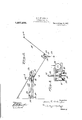
- Figure 1 is a diagrammatic side elevation illustrating my invention.
- Fig. 2 is an enlarged detail View thereof.
- Fig. 3 is a sectional view on the line 33 Fig. 2.
- 10 designates the stationary frame of the drawing machine, 11 the cage guided by said frame, 12 the cable leading to a suitable motor (not shown), for operating said cage, 13 the bait supported by said cage, and 14 the cylinder as it appears at the end of the drawing op eration and ready to be taken down.
- a cable 15 is secured at one end as indicated at 15*, to a part of the frame-work of the drawing frame, said point being fixed or stationary.
- the other end of the cable is connected to a trolley 16 mounted to reciprocate upon tracks 17 resting at one end upon an I-beam 18, the other end being supported by a hanger bar 19.
- Said trolley is provided. with suitable carrying wheels 21 which permit of the ready movement of the trolley along the track 17.
- the ends of the trolley are connected to the ends of a belt 22 passed around suitable pulleys 23 supported by the track 17, and operated by a motor 24 of any preferred type, and receiving its power from any suitable source.
- a trolley 25 mounted with carrying wheels 26, and a depending supporting yoke 27 which is yieldingly sustained by coiled springs 28.
- a hook 29 which engages a loop 30 of a hoop 31 passed around the lower end of the cylinder when the latter is to be taken down.
- the motor 24 is operated to move the trolley 16 to the point indicated in Fig. 1. This permits the trolley 25 to be lowered so that the hoop 31 may be passed over the lower end of the cylinder, and the loop 30 engaged with the hook 29. As soon as this is done the motor 24 isoperated to the support, the trolley 25 traveling along the cable 15. The operator then reverses the operation of motor 24, thus moving trolley 16 toward the drawing frame, thereby slackening the cable and allowing the cylinder to move down gently into the support.
- the taking down operation is greatly shortened and the spring 20 serves to relieve the cylinder of shocks to which it is normally subjected in the taking down process.
- the parts are simple in construction and counterweights, levers and the like now commonly employed are rendered unnecessary.
- An improved take-down mechanism for glass drawing apparatus comprising a cable having one end secured to a fixed point, a support for the other end of said cable, said support being movable toward and from said fixed point, means for controlling the movement of said movable support, and means mounted on the cable for supporting the severed end of the cylinder.
- An improved take-down mechanism for glass drawing apparatus comprising a cable having one end secured to a fixed point, a horizontally reciprocable support for the other end of said cable, said support being movable toward and from said fixed point, means for controlling the movement of said support, and means mounted on the cable for supporting the severed end of the cylinder.
- An improved take-down mechanism for glass drawing apparatus comprising a cable having one end secured to a fixed point, a horizontally movable support IP01 the other end of said cable, said support being movable toward and from said fixed point, a motor for controlling the movement of said support, and means mounted on the cable for supporting the severed end of the cylinder.
- An improved take-down mechanism for glass drawing apparatus comprising a cable having one end secured to a fixed point, a support for the other end of the cable, said support being movable toward and from said fixed point, means for controlling the movement of said support, cushioning means interposed between the cable and said movable support, and means mounted on the cable for supporting the severed end of the cylinder.
- An improved take-down mechanism for glass drawing apparatus comprising a cable having one end secured to a fixed point, a horizontally reciprocable support movable toward and from said fixed point, means for controlling the movement of said support, a spring connecting said support with the other end of said cable, and means mounted on the cable for supporting the severed end of the cylinder.
- An improved take-down mechanism for glass drawing apparatus comprising a cable having one end secured to a fixed point, a horizontal track, a trolley movable on said track toward and from said fixed point, means for operating said trolley, the other end of the cable being connected with said trolley, and means mounted on the cable for supporting the severed end of the cylinder.
- An improved take-down mechanism for glass drawing apparatus comprising a cable having one end secured to a fixed point, a horizontal track, a trolley movable 011 said track toward and from said fixed point and connected with the other end of said cable, a motor on said track, a belt operated by said motor and connected with said trolley, and means mounted on the cable for supporting the severed end of the cylinder.
- An improved take-down mechanism for glass drawing apparatus comprising a cable having one end secured to a fixed point, a horizontal track, a trolley movable on said track toward and from said fixed point, a spring connecting said trolley with the other end of said cable, means for operating said trolley, and means mounted on the cable for supporting the severed end of the cylinder.
Landscapes
- Chemical & Material Sciences (AREA)
- Engineering & Computer Science (AREA)
- Materials Engineering (AREA)
- Organic Chemistry (AREA)
- Manipulator (AREA)
Description
H.'E. D E VAUGHN. TAKE-DOWN DEVICE; APPLICATION FILEDNOVJB. 1914.
Patented Aug. 14, 1917.
2 SHEETSSHEET I.
+1. E. DE VAUGHN.
TAKE-DOWN DEVICE.
APPLICATION FILED NOV. 9, 1914.
Patented Aug. 14,1917.
2 SHEETSSHEET 2.
iinrrnn s'ra'rns ramanr ornrcn.
HARRY E. DE VAUGHN, OF MORGANTOWN, WEST VIRGINIA, ASSIGNOR OF ONE-HALF 'IO WALTER A. JONES, OF MOBGANTOVJN, WEST VIRGINIA.
TAKE-DOWN DEVICE.
Specification of Letters Patent.
Patented Aug. 14, 1917.
Application filed November 9, 1914. Serial No. 871,078.
To all whom it may concern:
Be it known that LHARRY E. DE VAUGHN, a citizen of the United States, residing at Morgantown, in the county of Monongalia and State of West Virginia, have invented new and useful Improvements in Take- Down Devices, of which the following is a specification.
This invention is an apparatus for taking down glass cylinders after the drawing operation has been completed.
One of the objects of the invention is to provide an apparatus by means of which the glass cylinder may be engaged while in vertical position, turned to a horizontal position, and be deposited upon a suitable horse or support. A further object is to provide means for shortening the time required for the take down operation without jeopardizing the safety of the cylinder. A further object is to provide means for cushioning the cylinder and relieving the same of shocks to which it is normally subjected in the take down process. A further object is to provide an apparatus of this character which does not necessitate the employment of counterweights, levers, and the like, now commonly employed with this type of apparatus.
The invention will be hereinafter fully set forth and particularly pointed out in the claims. I
In the accompanying drawings Figure 1 is a diagrammatic side elevation illustrating my invention. Fig. 2 is an enlarged detail View thereof. Fig. 3 is a sectional view on the line 33 Fig. 2.
Referring to the drawing, 10 designates the stationary frame of the drawing machine, 11 the cage guided by said frame, 12 the cable leading to a suitable motor (not shown), for operating said cage, 13 the bait supported by said cage, and 14 the cylinder as it appears at the end of the drawing op eration and ready to be taken down.
A cable 15 is secured at one end as indicated at 15*, to a part of the frame-work of the drawing frame, said point being fixed or stationary. The other end of the cable is connected to a trolley 16 mounted to reciprocate upon tracks 17 resting at one end upon an I-beam 18, the other end being supported by a hanger bar 19. I prefer to interpose a spring 20 between the end of the cable 15 and the trolley 16. Said trolley is provided. with suitable carrying wheels 21 which permit of the ready movement of the trolley along the track 17. The ends of the trolley are connected to the ends of a belt 22 passed around suitable pulleys 23 supported by the track 17, and operated by a motor 24 of any preferred type, and receiving its power from any suitable source. Mounted upon the rope 15 is a trolley 25 provided with carrying wheels 26, and a depending supporting yoke 27 which is yieldingly sustained by coiled springs 28. Depending from the yoke 27 is-a hook 29 which engages a loop 30 of a hoop 31 passed around the lower end of the cylinder when the latter is to be taken down.
In operation, when the cylinder 14 has been drawn to the desired height and severed at its lower end from the bath of molten glass, the motor 24 is operated to move the trolley 16 to the point indicated in Fig. 1. This permits the trolley 25 to be lowered so that the hoop 31 may be passed over the lower end of the cylinder, and the loop 30 engaged with the hook 29. As soon as this is done the motor 24 isoperated to the support, the trolley 25 traveling along the cable 15. The operator then reverses the operation of motor 24, thus moving trolley 16 toward the drawing frame, thereby slackening the cable and allowing the cylinder to move down gently into the support. By this arrangement the taking down operation is greatly shortened and the spring 20 serves to relieve the cylinder of shocks to which it is normally subjected in the taking down process. The parts are simple in construction and counterweights, levers and the like now commonly employed are rendered unnecessary.
Having thus explained the nature of my invention and described an operative manner of constructing and using the same, although without attempting to set forth all of the forms in which it may be made, or all of the forms of its use, what I claim is 1. An improved take-down mechanism for glass drawing apparatus, comprising a cable having one end secured to a fixed point, a support for the other end of said cable, said support being movable toward and from said fixed point, means for controlling the movement of said movable support, and means mounted on the cable for supporting the severed end of the cylinder.
2. An improved take-down mechanism for glass drawing apparatus, comprising a cable having one end secured to a fixed point, a horizontally reciprocable support for the other end of said cable, said support being movable toward and from said fixed point, means for controlling the movement of said support, and means mounted on the cable for supporting the severed end of the cylinder.
3. An improved take-down mechanism for glass drawing apparatus, comprising a cable having one end secured to a fixed point, a horizontally movable support IP01 the other end of said cable, said support being movable toward and from said fixed point, a motor for controlling the movement of said support, and means mounted on the cable for supporting the severed end of the cylinder.
4:. An improved take-down mechanism for glass drawing apparatus, comprising a cable having one end secured to a fixed point, a support for the other end of the cable, said support being movable toward and from said fixed point, means for controlling the movement of said support, cushioning means interposed between the cable and said movable support, and means mounted on the cable for supporting the severed end of the cylinder.
5. An improved take-down mechanism for glass drawing apparatus, comprising a cable having one end secured to a fixed point, a horizontally reciprocable support movable toward and from said fixed point, means for controlling the movement of said support, a spring connecting said support with the other end of said cable, and means mounted on the cable for supporting the severed end of the cylinder.
6. An improved take-down mechanism for glass drawing apparatus, comprising a cable having one end secured to a fixed point, a horizontal track, a trolley movable on said track toward and from said fixed point, means for operating said trolley, the other end of the cable being connected with said trolley, and means mounted on the cable for supporting the severed end of the cylinder.
7. An improved take-down mechanism for glass drawing apparatus, comprising a cable having one end secured to a fixed point, a horizontal track, a trolley movable 011 said track toward and from said fixed point and connected with the other end of said cable, a motor on said track, a belt operated by said motor and connected with said trolley, and means mounted on the cable for supporting the severed end of the cylinder.
8. An improved take-down mechanism for glass drawing apparatus, comprising a cable having one end secured to a fixed point, a horizontal track, a trolley movable on said track toward and from said fixed point, a spring connecting said trolley with the other end of said cable, means for operating said trolley, and means mounted on the cable for supporting the severed end of the cylinder.
In testimony whereof I have hereunto set my hand in presence of two subscribing witnesses.
HARRY E. DE VAUGHN. Witnesses Josnrrr L. KEENER, Rom. L. MITCHELL.
Copies of this patent may be obtained for five cents each, by addressing the Commissioner of Patents,
Washington, D. G.
Priority Applications (1)
| Application Number | Priority Date | Filing Date | Title |
|---|---|---|---|
| US87107814A US1237262A (en) | 1914-11-09 | 1914-11-09 | Take-down device. |
Applications Claiming Priority (1)
| Application Number | Priority Date | Filing Date | Title |
|---|---|---|---|
| US87107814A US1237262A (en) | 1914-11-09 | 1914-11-09 | Take-down device. |
Publications (1)
| Publication Number | Publication Date |
|---|---|
| US1237262A true US1237262A (en) | 1917-08-14 |
Family
ID=3305081
Family Applications (1)
| Application Number | Title | Priority Date | Filing Date |
|---|---|---|---|
| US87107814A Expired - Lifetime US1237262A (en) | 1914-11-09 | 1914-11-09 | Take-down device. |
Country Status (1)
| Country | Link |
|---|---|
| US (1) | US1237262A (en) |
-
1914
- 1914-11-09 US US87107814A patent/US1237262A/en not_active Expired - Lifetime
Similar Documents
| Publication | Publication Date | Title |
|---|---|---|
| US1237262A (en) | Take-down device. | |
| US1240821A (en) | Stone-breaker. | |
| US2015604A (en) | Portable jib crane | |
| US400798A (en) | Straw-stacker | |
| US890316A (en) | Take-down apparatus for glass cylinders. | |
| US835811A (en) | Coke-drawing machine. | |
| US961332A (en) | Mold-press. | |
| US832758A (en) | Ingot-stripping apparatus. | |
| US786339A (en) | Stone-sawing machine. | |
| US832988A (en) | Apparatus for drawing and handling coke and leveling coal. | |
| US897381A (en) | Elevator and carrier. | |
| US890317A (en) | Take-down apparatus for glass cylinders. | |
| US1166591A (en) | Guard for presses. | |
| US609960A (en) | Estelle | |
| US1144840A (en) | Wire-reeling apparatus. | |
| US310160A (en) | Leather-rolling machine | |
| US917688A (en) | Pneumatic hoist. | |
| US909606A (en) | Crane mechanism for ladles. | |
| US1263341A (en) | Apparatus for handling cylinders. | |
| US986105A (en) | Machine for splitting carcasses. | |
| US665227A (en) | Conveyer. | |
| US1107640A (en) | Machine for working hides and leather. | |
| US362381A (en) | Device for breaking bars | |
| US978412A (en) | Band-saw mill. | |
| US1203753A (en) | Splitting-machine. |