US1237246A - Edge-staining device for trimmed wall-paper. - Google Patents
Edge-staining device for trimmed wall-paper. Download PDFInfo
- Publication number
- US1237246A US1237246A US8093016A US8093016A US1237246A US 1237246 A US1237246 A US 1237246A US 8093016 A US8093016 A US 8093016A US 8093016 A US8093016 A US 8093016A US 1237246 A US1237246 A US 1237246A
- Authority
- US
- United States
- Prior art keywords
- paper
- edge
- trimmed
- trimming
- side edge
- Prior art date
- Legal status (The legal status is an assumption and is not a legal conclusion. Google has not performed a legal analysis and makes no representation as to the accuracy of the status listed.)
- Expired - Lifetime
Links
Images
Classifications
-
- B—PERFORMING OPERATIONS; TRANSPORTING
- B44—DECORATIVE ARTS
- B44C—PRODUCING DECORATIVE EFFECTS; MOSAICS; TARSIA WORK; PAPERHANGING
- B44C7/00—Paperhanging
- B44C7/02—Machines, apparatus, tools or accessories therefor
- B44C7/04—Machines, apparatus, tools or accessories therefor for applying adhesive
Definitions
- the presentinvention relates'to a device or appliance for placing coloring matter of the same character as the background of Wall-paper to the side trimmed edges thereof.
- One .object of the invention is t'o provide an appliance which will apply a' coloring matter to the side trimmed edge of Wallpaper as it is fed through a trimming and pasting machine.
- a further object of the invention is to so construct such appliance that it Will. apply the coloring matter directly to the side edge of the paper, thus eliminating the White or of-color streak along said trimmedl edge, Which wouldvotherwise appear when the p aper is placed upon the wall'.
- a further object of the invention is to provide a simple and compact appliance for -doing this work, and tot provide means for pressing the paper into constant contact with the coloring matter distributing member of such appliance.
- a further object of the invention is to provide a flange or shoulder on the color applying member, which Vwill act to place.
- the coloring matter along 'the trimmed side edge without applying it to the decorated surface of the paper, and also serve as a guide in the forward travel of the paper.
- a further object of the invention is to so arrange and mount the appliance of the present invention as to enable itv to be adjusted to accommodate dierent widths of paper.
- the invention further consists in the features of construction and combination of parts hereinafter described and claimed.
- Figure l is a cross section of a Wall-paper pasting and cutting machine equipped With the appliance of the present invention.
- Fig. 2 a plan view of a portin of said machine, showing the appliance of the present invention
- Fig. 3' a plan view ofthe appliance of the present invention
- Fig. 4 a sectionn line ll-- of Fig. 3, looking in the direction of the arrows;
- the edge-staining or coloring device of the present invention is specifically adapted for use with that type of Wall-paper, trimming and pasting machines in which side trimmers are provided-for cuttingof the margin of the paper to leave the edges per'- fectly smooth and parallel, in order that when the paper is hung, the edges abut rather than overlap, this abutting of the edges -being in accordance with the most modern practice of hanging Wall-paper.
- the principal object, therefore, of the present invention is to apply the proper tint or color to the trimmed side edge of the paper by mechanical means and in a regular and uniform manner, and to carry on this operation simultaneously with the feeding of the-paper through the machine, entailing no further operations than are gone through inthe ordinary preparation 'of the paper l'for hanging by the use of such machines.
- the machine With which the present invention is shown as* employed consists of side plates-6 joined together by suitable vtie rods 7; and'suspended from a rod 7 held in the side plates is a hanger 8 comprising arms 8a held in place by means of straps or links 9. These straps are removable to allori7 one or both of the arms 8a to be removed and permitthe mounting of fresh rolls of paper.
- This hanger serves to carry a roll of Wallpaper 10 which is mounted on a rod 10a.
- Mechanism for trimming the sides of said paper is shown, comprising a cutting disk 11, acting upon a backing roll 12, both disk and roll being provided with overlapping circular cutters.
- a tank 13 for a pasting medium is also carried by these side plates and is supported by suitable cross supports .14. Adapted to revolvepartially Within and partially Without this tank is a paste applying- Wheel or roller 15, mounted upon a shaft 16, 'which latter is suitably driven. A scraper 17 is provided for removing the surplus paste/ from the pasting roller 15, Which scraper is mounted upon a rocking crossshaft or bar 18. A feed roller 19 isprovided, With which coperates a pressure roller 20, carried by an arm 21, said pressure roller 20 serving to distribute and thin the paste evenly over the face of the paper to which it has been applied by tue roller 15. A. scraper 22 for each side edge of the paper is provided for removing any excess paste from the marginal edges of the paper, so that When the paper is hung, thispaste Will not be squeezed out and onto the outer surface of the paper.
- the subject-matter of the present inven- ⁇ tion is illustrated in detail in Figs. 3, 4 and 5, and comprises a ⁇ receptacle 34 formed With a Well for the purpose of receiving a suitable stain or coloringsolution'.
- a lug 36 formed with a holev 37 extending therethrough. This hole receives a rod 38 secured to the plate 6; and the lug 36 is tapped, as at 40, to receive ⁇ a set screw 39 for locking the receptacle 34 to said Iod.
- the receptacle can be adjusted back and forth on the rod 38, so as to properlyposition it With respect to the side edge of different Widths of paper.
- roller 41 Mounted within the receptacle 34 is a roller 41, against the surface Vof Which operatesy a scraper 42; and this roller is formed with a shoulder 43, which provides a surface that Will contact the trimmed side edge of the paper and-apply color thereto, and which also serves as a guide for the paper 'as it is passing through.
- the roller is mounted to revolve upon a stem 44, and, as shown, is locked inplace by a locking member 45. As Will be seen, the roller revolves partially within and partially Without the Well 35 of the receptacle 34, and it is-this member which acts to apply the tinting or coloremployed. y
- the color applying mechanism of the present invention is placed in advance of the side trimming cutters 11, soy that the coloring mattei is applied after the side trimming operation, as, of course, is essential, since it is the side trimming operationv that produces the objectionable White. or offcolor edge. It is also to be noted that the color applying mechanism is located rearward of the pasting appliance, so that the paste. is applied after the edge has been tinted or colored.
- the trimming roilersll one at each side of themachine, serve to trim both side edges thereof, and each edge of the paper is then subjected to the action of the roller 4l (there being a roller for each edge), whereby coloring matter is placed upon both of tbe trimmed edges, staining or coloring the edges the same color as the background of the paper. It is apparent that this Work is carried on continuously as the paper is fed through the machine, and that the paper does not have to be subjected to any further operations, save the usual operations of feedl ing the paper through the machine.
- the combination with paper-feeding mechanism mechanism for trimming the side edge of the paper, and means for applying paste ⁇ to the paper after the side trimming operation, of mechanically operating means, located between the side trimming mechanism and paste-applying mechanism, for applying coloring matter to the trimmed side edge,
- a roller operating partially within and partially without said receptacle, and means for holding the paper in contact with said roller. whereby coloring matter is applied to the trimmed side edge of the paper, substantially as described.
- the combination with paper-feeding mechanism, and mechanism for trimming the side edge of the paper, of a receptacle for coloring matter located in advance of the side trimming mechanism. and means for extracting 4the coloring matter from the receptaele tothe trimmed side edge and under. face of the paper, substantially as described.
- said means comprising an upper and lower member between which the paper passes, and
Description
WILLIAM JfDUNN, 0F MONTREAL, QUEBEC, CANADA EDGE-STAINING DEVICE FOR TRIMMED WALL-PAPER.
Specication of Letters Patent.
atented Aug. 14, 1917.
Application led February 28, 1916. Serial No. 80,930.
To all whom t may concern:
Be it known that I, WILLIAM J. DUNN, a subject of the King of Great Britain, residing at Montreal, in the Provinceof Quebec and Dominion of Canada, have invented certain new and useful Improvements in Edge-Staining Devices for Trimmed Wall- Paper, of which the following is a specification.
'The presentinvention relates'to a device or appliance for placing coloring matter of the same character as the background of Wall-paper to the side trimmed edges thereof.
One .object of the invention is t'o provide an appliance which will apply a' coloring matter to the side trimmed edge of Wallpaper as it is fed through a trimming and pasting machine.
A further object of the invention is to so construct such appliance that it Will. apply the coloring matter directly to the side edge of the paper, thus eliminating the White or of-color streak along said trimmedl edge, Which Wouldvotherwise appear when the p aper is placed upon the wall'. A
A further object of the invention is to provide a simple and compact appliance for -doing this work, and tot provide means for pressing the paper into constant contact with the coloring matter distributing member of such appliance.
A further object of the invention is to provide a flange or shoulder on the color applying member, which Vwill act to place.
the coloring matter along 'the trimmed side edge without applying it to the decorated surface of the paper, and also serve as a guide in the forward travel of the paper.
A further object of the invention is to so arrange and mount the appliance of the present invention as to enable itv to be adjusted to accommodate dierent widths of paper.
The invention further consists in the features of construction and combination of parts hereinafter described and claimed.
In the drawings: i
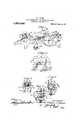
Figure l is a cross section of a Wall-paper pasting and cutting machine equipped With the appliance of the present invention; i
Fig. 2, a plan view of a portin of said machine, showing the appliance of the present invention;
Fig. 3', a plan view ofthe appliance of the present invention;
Fig. 4, a sectionn line ll-- of Fig. 3, looking in the direction of the arrows; and
Fig. 5, a section on line 5-5 of Fig. 4,
looking in the direction of the arrows.
' The edge-staining or coloring device of the present invention is specifically adapted for use with that type of Wall-paper, trimming and pasting machines in which side trimmers are provided-for cuttingof the margin of the paper to leave the edges per'- fectly smooth and parallel, in order that when the paper is hung, the edges abut rather than overlap, this abutting of the edges -being in accordance with the most modern practice of hanging Wall-paper.
It has been found in practice that in trimming the marginal edge of Wall-paper, a white line or surface is lproduced along such trimmed edge, with the result that when the paper is hung, a division line is formed between each strip orl section of paper, by reason of the white or oft-color edges produced by the side. trimming operation coming together. This exposed line of contact disfigures the appearancev of the paper and tends to destroy the continuity of the design or pattern. It is therefore highly desirable that these white or of-color edges produced by the side trimming operation be of the same color and character as the body ofV the paper, thus producing, when the paper is placed upon the Wall, a continuing expanse ofv colored background and eliminating the White or olf-color division lines. Heretofore this tinting or coloring has been done by hand, which is a slow and tedious o eral tion, and not 1n every instance success as to the results sought. f
-The principal object, therefore, of the present invention is to apply the proper tint or color to the trimmed side edge of the paper by mechanical means and in a regular and uniform manner, and to carry on this operation simultaneously with the feeding of the-paper through the machine, entailing no further operations than are gone through inthe ordinary preparation 'of the paper l'for hanging by the use of such machines.
Although the present invention has been illustrated in connection with a certain type of Wall-paper pasting and trimming machine, it is to be understood that the particular mechanism shown and vdescribed is 'only for the purpose of showing one means of practising the invention; and the invention is not limited thereby except as some portions of the mechanism may be claimed broadly for the purpose of making` an operative combination.
Referring now to the drawings, and particularly to Figs. 1 and 2, the machine With which the present invention is shown as* employed, consists of side plates-6 joined together by suitable vtie rods 7; and'suspended from a rod 7 held in the side plates is a hanger 8 comprising arms 8a held in place by means of straps or links 9. These straps are removable to allori7 one or both of the arms 8a to be removed and permitthe mounting of fresh rolls of paper. This hanger serves to carry a roll of Wallpaper 10 which is mounted on a rod 10a. Mechanism for trimming the sides of said paper is shown, comprising a cutting disk 11, acting upon a backing roll 12, both disk and roll being provided with overlapping circular cutters. A tank 13 for a pasting medium is also carried by these side plates and is supported by suitable cross supports .14. Adapted to revolvepartially Within and partially Without this tank is a paste applying- Wheel or roller 15, mounted upon a shaft 16, 'which latter is suitably driven. A scraper 17 is provided for removing the surplus paste/ from the pasting roller 15, Which scraper is mounted upon a rocking crossshaft or bar 18. A feed roller 19 isprovided, With which coperates a pressure roller 20, carried by an arm 21, said pressure roller 20 serving to distribute and thin the paste evenly over the face of the paper to which it has been applied by tue roller 15. A. scraper 22 for each side edge of the paper is provided for removing any excess paste from the marginal edges of the paper, so that When the paper is hung, thispaste Will not be squeezed out and onto the outer surface of the paper.
The paper, after leaving the Scrapers 22,
- passes over a suy'iporting rod 23, thence over a roller 24, and between discharge rollers 25 and 26. After leaving` said discharge rollers, the paper passes across a. plate o 'r table 27, above vvhichis located a cross-cutter 28 actuated crosswise of the paper by a handle 29. The paper then passes onto an apron'30, which is supported bv a suitable support 31. Located above the roller 24 is a shiftable cutter 32, one for each side of the machine, for cutting oif sections from the paper of such width as may be desired. A guide or,
indicator mounted upon a standard or support 34 is provided, which is for the purpose of enabling the operator to 'determine at what point in the pattern each length of paper is tobe severed in order to have the pattern match properly.
All of the fregoing described parts are mechanism which go to make up a practical machine for trimming and pasting Wallpaper, is fully shown and described in my co-pending application, Serial vNo. 80,929, filed by me February 23, 1916, and entitled Machines for trimming and pasting Wall paper, but, as heretofore stated, the
precise mechanism shown and described is .75
of, is believed to benecessary in connection With the present invention.
The subject-matter of the present inven-` tion is illustrated in detail in Figs. 3, 4 and 5, and comprises a` receptacle 34 formed With a Well for the purpose of receiving a suitable stain or coloringsolution'. Extending from the lower end of the receptacle 35 is a lug 36 formed with a holev 37 extending therethrough. This hole receives a rod 38 secured to the plate 6; and the lug 36 is tapped, as at 40, to receive `a set screw 39 for locking the receptacle 34 to said Iod. By means of this arrangement, the receptacle can be adjusted back and forth on the rod 38, so as to properlyposition it With respect to the side edge of different Widths of paper.
Mounted Within the receptacle 34 is a roller 41, against the surface Vof Which operatesy a scraper 42; and this roller is formed with a shoulder 43, which provides a surface that Will contact the trimmed side edge of the paper and-apply color thereto, and which also serves as a guide for the paper 'as it is passing through. The roller is mounted to revolve upon a stem 44, and, as shown, is locked inplace by a locking member 45. As Will be seen, the roller revolves partially within and partially Without the Well 35 of the receptacle 34, and it is-this member which acts to apply the tinting or coloremployed. y
ing matter to the trimmed side edge of the r paper.
Referring now to Fig. 5, it Will be seen that when in operation, the paper extends across the surface of said roller and abuts against the shoulder 43. This shoulder tends to apply coloring matter directly to ,the trimmed side edge of the paper, which edge mounted upon a stem 47, Which. is carried by an arm 48 pivoted as at 49, and held under downward tension by means of the rin 5l, which 1s secured at one end 'by a hook be objectionable,
50 on the arm 48, and at the other end by a lug 52 on the side of the casing 34.
By referring now to Fig. A1, it will be seen that the color applying mechanism of the present invention is placed in advance of the side trimming cutters 11, soy that the coloring mattei is applied after the side trimming operation, as, of course, is essential, since it is the side trimming operationv that produces the objectionable White. or offcolor edge. It is also to be noted that the color applying mechanism is located rearward of the pasting appliance, so that the paste. is applied after the edge has been tinted or colored.
It will Ibe apparent from the foregoing description that, as the paper is fed through the machine, the trimming roilersll, one at each side of themachine, serve to trim both side edges thereof, and each edge of the paper is then subjected to the action of the roller 4l (there being a roller for each edge), whereby coloring matter is placed upon both of tbe trimmed edges, staining or coloring the edges the same color as the background of the paper. It is apparent that this Work is carried on continuously as the paper is fed through the machine, and that the paper does not have to be subjected to any further operations, save the usual operations of feedl ing the paper through the machine.
By applying the coloring or tinting matter in the manner set forth, such matter is applied only to the under face and side edge of thev paper, and is not'placed upon the decorated surface of the paper, which would in that it might vbecome smeared in the later operation of applying the paper to the wall. Although the mechanism has been described with considerable detail, the use of iother and equivalent means is contemplated, and, in fact, the invention is not limited other than may be set forth by the terms of the appended claims.
I claim: V
1. In an appliance of the class described, the combination with paper-feeding mechanism, and mechanism for trimming the side edge of the paper, of means for applying coloring matter to said trimmed side edge, substantially as described.
2. In an appliance. of the class described, the combination with paper-feeding mechanism. mechanism for trimming the side edge of the paper, and means for applying paste` to the paper after the side trimming operation, of mechanically operating means, located between the side trimming mechanism and paste-applying mechanism, for applying coloring matter to the trimmed side edge,
substantially as described.
3. In an appliance of the class described, the combination with paper-feeding mechanism. and mechanism for trimming the side edge of the paper, ol a receptacle for eoland applying it paper, and spring-pressed means for holdoring matter, located in advance of the side trimming mechanism. and means for extracting the coloring matter from said receptacle and applying it to said trimmed side edge, substantially as described.
el. In an appliance of the class described, the combination with paper-feeding mechanism, and mechanism for trimming the side edge of the paper, ot' a receptacle for coloring matter, located in advance of the side trimmingr mechanism. a roller operating partially within and partially without said receptacle, and means for holding the paper in contact with said roller. whereby coloring matter is applied to the trimmed side edge of the paper, substantially as described.A
5. In an appliance of the cla described, the combination with paper-feeding mechanism, and mechanism for trimming the side edge of the paper, of a receptacle for coloring matter. located in advance of the side trimming mechanism. and means for extracting 4the coloring matter from the receptaele tothe trimmed side edge and under. face of the paper, substantially as described.
6. In an appliance of the class described, the combination with paper-feeding mechanism, and mechanism for trimming the side edge of the paper, of a receptacle for coloring matter located in advance of the side trimming mechanism. means for extracting the coloring matter from the receptacle and applying it to the trimmed side edge of the 100 ing said paper in engagement with said coloring matter applying means, substantially as described.
7. In an appliance of the class described, the combination of paper-feeding mechanism, mechanism for trimming the' side edge of the paper, means for applying coloring matter to said trimmed side edge, and means for adj ust-ing said coloring matter applying means to accommodate different widths of paper, substantially asdescribed.
8. In an appliance ofthe class described, the. combination of paper-feeding mechanism. mechanism for trimming the side edge of the paper` a receptacle for coloring matter. means for extracting coloring matterA from the receptacle and applying 1t to the trimmed side edge. of the paper, a member on which said kreceptacle is mounted ,and means permitting adjustment of said receptacle upon said mounting'to accommodate different widths of paper, substantially as described.
9. In an applianee'of the class described,
lthe combination with paper-feeding mecha- 125 ingsaid lug from said receptacle having an therethrough, a rod eXtendin and means pending opening through P Without scid receptacle for coloring matter to the trimmed side edge of the paper, substantially as described.
Iran appliance of the class described, the combination or" paper-feeding mechamechanism for trimming the side edge of thepaper, of a receptacle for coloring matter, located in advance of the trimming mechanism, a flanged roller mounted partially Within and partially Without said receptaclefor applying the coloring matter tothe trimmed side edge ofth a spring-pressed member for holding the paper in Contact With the 'surface of the roller and against the Harige thereof, substantially as described.
i2. n a device of the class described, the
Geniee? this permet my he obtained for five cents each, by addressing the Gcmmissicner of ing operation, siibstantially menace combination of' a receptacle for aI tinting medium, an endless member adapted to receive said medium on th o paper with its trimmed side edge against iiange, whereby the tinted medium is applied to said edge, substantially as described.
13. In described, the
medium, and means for applying such me- 4duim to a trimmed side edge of wall paper,
said means comprising an upper and lower member between which the paper passes, and
means associated with the lower member for contacting said trimmed side edge and applying the medium thereto, substantially as escribed.
14. In a device oi the vclass described, the combination of areceptacle for a tinting medium, a roller rotatingr partially within and partially Without said receptacle, 'a
ange on the roller medium to the trimmed side edge. of the paper and for guiding the paper in its passage, and means described.
WELLIAM J. DUNN.
Patente,
Y Washington, D. C.
for a tinting
Priority Applications (1)
| Application Number | Priority Date | Filing Date | Title |
|---|---|---|---|
| US8093016A US1237246A (en) | 1916-02-28 | 1916-02-28 | Edge-staining device for trimmed wall-paper. |
Applications Claiming Priority (1)
| Application Number | Priority Date | Filing Date | Title |
|---|---|---|---|
| US8093016A US1237246A (en) | 1916-02-28 | 1916-02-28 | Edge-staining device for trimmed wall-paper. |
Publications (1)
| Publication Number | Publication Date |
|---|---|
| US1237246A true US1237246A (en) | 1917-08-14 |
Family
ID=3305065
Family Applications (1)
| Application Number | Title | Priority Date | Filing Date |
|---|---|---|---|
| US8093016A Expired - Lifetime US1237246A (en) | 1916-02-28 | 1916-02-28 | Edge-staining device for trimmed wall-paper. |
Country Status (1)
| Country | Link |
|---|---|
| US (1) | US1237246A (en) |
-
1916
- 1916-02-28 US US8093016A patent/US1237246A/en not_active Expired - Lifetime
Similar Documents
| Publication | Publication Date | Title |
|---|---|---|
| US1999224A (en) | Cigarette making machine | |
| US1237246A (en) | Edge-staining device for trimmed wall-paper. | |
| US2662452A (en) | Machine for making printed, corrugated box blanks | |
| US1476988A (en) | Carbonizing machine | |
| US2232274A (en) | Inking appliance for marking machines | |
| US1724208A (en) | Means for trimming selvage edges of rubberized fabrics | |
| US1016011A (en) | Strip-moistening machine. | |
| US1949188A (en) | Manufacture of paper | |
| US1368933A (en) | Machine for the simultaneous slitting and artificial selv aging of | |
| US504551A (en) | Box-covering machine | |
| US2117840A (en) | Apparatus for face saturating porous materials in the manufacture of hard surface floor coverings | |
| US1334387A (en) | Wall-paper pasting and trimming machine | |
| US1957238A (en) | Puller feed machine | |
| US272436A (en) | Wall-paper-hanging machine | |
| US2324950A (en) | Edge trimming means for use in rotary printing presses | |
| US636071A (en) | Stencil-printing machine. | |
| US1184284A (en) | Machine for pasting and trimming wall-paper. | |
| US1233377A (en) | Machine for making plaited paper. | |
| US2146507A (en) | Coating machine | |
| US1193615A (en) | Flong-machine | |
| US665844A (en) | Machine for manufacturing carbon-coated paper. | |
| US1026934A (en) | Printing-press. | |
| US1990599A (en) | Ornamenting machine | |
| US2277960A (en) | Moistening mechanism | |
| US2065545A (en) | Surface decorating method and apparatus |