US1237178A - Land-marker. - Google Patents
Land-marker. Download PDFInfo
- Publication number
- US1237178A US1237178A US11628016A US11628016A US1237178A US 1237178 A US1237178 A US 1237178A US 11628016 A US11628016 A US 11628016A US 11628016 A US11628016 A US 11628016A US 1237178 A US1237178 A US 1237178A
- Authority
- US
- United States
- Prior art keywords
- marker
- bar
- arm
- planter
- shaft
- Prior art date
- Legal status (The legal status is an assumption and is not a legal conclusion. Google has not performed a legal analysis and makes no representation as to the accuracy of the status listed.)
- Expired - Lifetime
Links
Images

Classifications
-
- A—HUMAN NECESSITIES
- A01—AGRICULTURE; FORESTRY; ANIMAL HUSBANDRY; HUNTING; TRAPPING; FISHING
- A01B—SOIL WORKING IN AGRICULTURE OR FORESTRY; PARTS, DETAILS, OR ACCESSORIES OF AGRICULTURAL MACHINES OR IMPLEMENTS, IN GENERAL
- A01B69/00—Steering of agricultural machines or implements; Guiding agricultural machines or implements on a desired track
- A01B69/02—Ridge-marking or like devices; Checkrow wires; Accessories therefor
- A01B69/024—Ridge-marking or like devices; Checkrow wires; Accessories therefor adapted to cut and form a ridge or forrow in the soil surface, e.g. with a disc
Definitions
- DIRK DE VRIES or ooR'oNA.
- 'soUTH DAKOTA AssIGNon or ONE-HALF 'ro WILLIAM WESTENIIELD, or WASHINGTON, DISTRICT 0F COLUMBIA.
- the object'of my invention is to provide a marking attachment for a planter. which may be readily raisedfrom 0r lowered to the ground, and which may be quickly. shifted from one side of the planter to the other by mechanism driven from the ground wheels of the planter. and completely within the control of. the' operator;
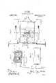
- Figure 1 is a rear elevation of my marker applied to a planter and showing both the operative and inoperative position' of the marker arm.
- Fig. i) is an enlarged rear elevation of the rear cross bar of the planter frame.
- Fig. 3 is a top plan view of a planter having my marker attached thereto.
- Fig. 4 is an enlarged vertical section on ⁇ the line 4 4 of Fig. 3.
- Fig. 5 is an enlarged fragmentary front view of the marker arm and the frame. carrying the same.
- a planter vis show-n having a rectangular frame consist-v ing of side bars 1.
- front and rear cross pieces 2 and 3 respectively cross braces 8.
- a tongue ⁇ rl attached to the front cross piece, seedboXes 5 at cach side of the front of the machine, and an axle 6 extendingl transversely of the vehicle between the cross bars, and journaled in the side bars 1 ⁇ and carrying standard ground Wheels 7.
- a shaft 'extending longitiidinallv. of the shaft 14. b vy -means of may be rocked.
- the planter frame at the center thereof is journale'd in the rear cross piece 2 and one ofthe ⁇ cross braces S, and carries a bevel gear 10 on its Inner end,A which 1s url]acent the a. ⁇ "le G.
- the axle G has two .inwardly facing spaced bevel gears 1l slidably keyed thereon at opposite sides of the bevel ⁇ gear 10 ⁇ and adapted to have one or the other brought into mesh ,with the bevel gear 10 as desired.
- the bevel gears 11 are held normally spaced apart ⁇ and from :the gear 10 b v a coiled spring 12, the ends of which bear against the opposed faces of the gears, the-y outward movements of the lat-ter upon the axle G being checked b v suitable pins 13.
- a rocking shaft 1l is mounted longitudibraces S in rear of each of the' bevel gears,y
- This bar 19 has a. channel Q0 extending the length of Vthe same upon its inner face, through which the marker armA 21 is adapted to slide;
- the rear cross bar 3 has channels or slots 22 formed in its face which is ⁇ adjacent the bar 19. extending fromv eaqh end 'of thev same to points near thecenter'of. he bar ⁇ as shown in Fig. Q ⁇ and 'the outer ein ⁇ s of these slots are. outwardly dared as shown at 23. The inner ends of the slots are upwardly curved as shown 'at 24. head Qll is carried b v vthe outer end of the shaft 9 and serves to prevent the accidental displacement of the, bar 19. l
- the Amarkezuarm 21 which. slides in the channel Q0, extends beyond the planter at each side thereof and carries amarking shoe Q5 at each end.
- the mechanism for shifting the marker arm 21 transversely of the planter consists ofl a cable 27 secured to, and having'its ccnt-ral portion wound upon the shaft il in rear of the cross bar 3, and having its ends threaded through openings 2S in a suitable supportl 29, extending rearwardly of the central portion of the cross bar 3, and thence passing around pulleys 30 at each side of the center of the top of the cross piece 3, thence around pulleys 3l upon the outer ends of the cross bar 3, and thence to each end of the-marker arm respectively, where they are secured.
- a spring latch 32 is-pivoted to the rear end of one of the side bars 1 of the planter, and is adapted to engage the marker arm supporting bar 19 a'nd the rear cross bar 3 so as to prevent rotation of the former relative to the latter as clearly shown in Fig. l.
- the shaft 9 is rotated in the opposite direction, pulling the marker-arm in the opposite direction.
- a land marker the combination with a fralne having a rear cross member, of an axle having supporting wheels thereon. a shaft extending longitudinally of the trame, a reversible clutch between the said shaftand axle for rotating the said shaft in either direction, a bar pivoted upon this said shaft and abutting against the said rear cross member, the said bar having a channel extending the length of the same upon its face adjacent the said cross member, an arm ha ving marking shoes upon its ends adapted to slide within the said channel, the said cross member having a slot with an upwardly curved inner end, extending from each end of the cross member to points adjacent the center of the same rollers upon the said i marker arm adapted to engage each of the said slots near their outer ends, a cable sccured to, and having its central portion .wound upon the above mentioned shaft and having an end secured to each end ofthe marker arm, and a latch adapted to hold the said bar against rotation relative to the rear cross member.
- a land marker the combination with a frame having a rear cross member, ot a marker arm secured to the said cross member in such a manner that it may be slid transversely of the frame and have its outer end swung do ⁇ 'n ⁇ var 'lly into engagement with the soil, the said cross member having a slot with an upwardly curved inner end ⁇ extending from each end of the cross member to points adjacent the center ot' the same. rollers upon the said marker arm adapted to engage each of the said slots near their outer ends, and means for sliding the said marker arm to one side or the other of the trame.
Description
u. DE vmes,
LAND ummm..v APPLICATION FILED AUG-22| I9I6.-
1,23'?,178, Plfcented Aug. 14, 1917. I
2 SHEETS-SHEET 1.
-v if 5 j I .QM mi D. DE VRIES.
LAND MARKER.
APPLICATION FILED AUG-2 2, 1916. 1,23%178. I Patented Aug. 14,1917.
2 SHEETS-SHEET 2.
'r--l/x J l an d *'"h m )i 1 o o NS u 1 o o 1% Ef J-`- 1 P o M 1 s i A W 1 1 S1 #www R N invrran sTATas PATENT onnicn.-
DIRK DE VRIES, or ooR'oNA. 'soUTH DAKOTA; AssIGNon or ONE-HALF 'ro WILLIAM WESTENIIELD, or WASHINGTON, DISTRICT 0F COLUMBIA.
LAND-MARKER.
Specicationot Letters Patent.
Patented'Aug. T4, 1am.'
Application filed August 22. 1916. i Serial No. 116,280.
The object'of my invention is to provide a marking attachment for a planter. which may be readily raisedfrom 0r lowered to the ground, and which may be quickly. shifted from one side of the planter to the other by mechanism driven from the ground wheels of the planter. and completely within the control of. the' operator;
.\ further object of my invention is to l f provide a marker of this'type of few parts and of simple but durable constructioinand therefore not liable to break or become inoperative from any cause. lVith these 4and other objects in view'l whichwill become apparent as the description proceeds, my invention resides in the construction, combination, and arrangementv of parts to be hereinafter described and claimed, 'and illustrated in the accompany? ing drawings forming a part of this specification. and in which like reference characters indicate like parts 'throughout the several views. 1
Figure 1 is a rear elevation of my marker applied to a planter and showing both the operative and inoperative position' of the marker arm.
Fig. i) is an enlarged rear elevation of the rear cross bar of the planter frame. A
Fig. 3 is a top plan view of a planter having my marker attached thereto.
Fig. 4 is an enlarged vertical section on` the line 4 4 of Fig. 3.
Fig. 5 is an enlarged fragmentary front view of the marker arm and the frame. carrying the same.
Referring to the drawings. a planter vis show-n having a rectangular frame consist-v ing of side bars 1. front and rear cross pieces 2 and 3 respectively cross braces 8. a tongue `rl attached to the front cross piece, seedboXes 5 at cach side of the front of the machine, and an axle 6 extendingl transversely of the vehicle between the cross bars, and journaled in the side bars 1` and carrying standard ground Wheels 7.
A shaft 'extending longitiidinallv. of the shaft 14. b vy -means of may be rocked.
planter frame at the center thereof, is journale'd in the rear cross piece 2 and one ofthe` cross braces S, and carries a bevel gear 10 on its Inner end,A which 1s url]acent the a.\"le G. The axle G has two .inwardly facing spaced bevel gears 1l slidably keyed thereon at opposite sides of the bevel `gear 10` and adapted to have one or the other brought into mesh ,with the bevel gear 10 as desired.
The bevel gears 11 are held normally spaced apart` and from :the gear 10 b v a coiled spring 12, the ends of which bear against the opposed faces of the gears, the-y outward movements of the lat-ter upon the axle G being checked b v suitable pins 13.
A rocking shaft 1l is mounted longitudibraces S in rear of each of the' bevel gears,y
and has a yoke formed therein having an The rear cross piece 3 of the'plauter frame which. the shaftl 14 .nally of this planter frame'between the cross.
has a bearing 17 formed in a 'downwardly projecting lug -18 lon its lower surface, through which passes thev outer e11 lof'the.
shaft-9.v Upon the outer end of this shaftis pivotally secured a'bar 1910i' substantially the same length as the cross piece 3. and
adapted to fit against the rear of the same.
This bar 19 has a. channel Q0 extending the length of Vthe same upon its inner face, through which the marker armA 21 is adapted to slide;
The rear cross bar 3 has channels or slots 22 formed in its face which is` adjacent the bar 19. extending fromv eaqh end 'of thev same to points near thecenter'of. he bar` as shown in Fig. Q` and 'the outer ein` s of these slots are. outwardly dared as shown at 23. The inner ends of the slots are upwardly curved as shown 'at 24. head Qll is carried b v vthe outer end of the shaft 9 and serves to prevent the accidental displacement of the, bar 19. l
The Amarkezuarm 21 which. slides in the channel Q0, extends beyond the planter at each side thereof and carries amarking shoe Q5 at each end.
A rearwardly -extending roller Q6 adapted lto slide in eachof the Y slots 22 in the rear cross piece 3, is secured to the inner face of the marker arm at each side of the center thereof, in sucha position that when the marker arm is in its central or inoperative position, the rollers 26 will engage the slots 22 near their outer ends.
The mechanism for shifting the marker arm 21 transversely of the planter consists ofl a cable 27 secured to, and having'its ccnt-ral portion wound upon the shaft il in rear of the cross bar 3, and having its ends threaded through openings 2S in a suitable supportl 29, extending rearwardly of the central portion of the cross bar 3, and thence passing around pulleys 30 at each side of the center of the top of the cross piece 3, thence around pulleys 3l upon the outer ends of the cross bar 3, and thence to each end of the-marker arm respectively, where they are secured.
A spring latch 32 is-pivoted to the rear end of one of the side bars 1 of the planter, and is adapted to engage the marker arm supporting bar 19 a'nd the rear cross bar 3 so as to prevent rotation of the former relative to the latter as clearly shown in Fig. l.
In the operation of my invention, assuming that the machine is about to sta-rt a new row, under which condition the marker arm supporting bar will beheld against the rear of the rearcross arm by latch 32, and the marker arm will beheld in a horizontal position With its center at the center of the supporting bar, and the rollers 26 engaging in the slots 22 at each end of the' cross bar 3, the operator in order tov lower one of the marking shoes to the ground, will swing back the latch 32 and press upony one of the foot levers 16, thereby throwing one or the other of the bevel gears upon the axle 6 into engagement with the gear 10, thus rotating the shaft 9 in one direction or the other, and so Winding in one end of the .cable and paying out the other end. This will slide the marker arm within its support until one of the rollers 26 is free of the slot 22, and the other roller slides into the upwardly curved end of the' other slot, thereby turning the marker arm supporting bar 19 upon the sha't't 9, and so depressing one end of the marker arm until the marking'shoe engages the soil, as shown in dotted lines in Fig-1.
To return the marker arm to its horizontal or inoperative position, the shaft 9 is rotated in the opposite direction, pulling the marker-arm in the opposite direction. and
causing the inner roller to slide back into the straight portion of the slot 22, thereb \r swinging the bar 19 back to its horizontal position, and causing the outer` roller to slide back intol the slot 22, guided-by the outwardly flaring mouth 23.
Whenthe marker arm is again at its central position, the shaft 9 is disengaged from the axle 6, and the device secured b v this latch 32, or if it is desired to lower the marking shoe upon the opposite end of the arm, the marking arm is pulled beyond its central position, in which case the above described operation is repeated upon the opposite side of the machine.r l
It will thus be seen from the foregoing description that I have provided a land marker for a planting machine which may be quickly swung to an operative position at either side-of the planter, or may be held in an inoperative'position centrally of the machine, thus occupying only a small amount of space. when not in use; and that eI have further provided a marking device which is shifted from one position to another 'by power taken from the axle of the planter, thereby reducing the labor incident to the operation of the machine. v
l claim: l
1. In a land marker, the combination with a fralne having a rear cross member, of an axle having supporting wheels thereon. a shaft extending longitudinally of the trame, a reversible clutch between the said shaftand axle for rotating the said shaft in either direction, a bar pivoted upon this said shaft and abutting against the said rear cross member, the said bar having a channel extending the length of the same upon its face adjacent the said cross member, an arm ha ving marking shoes upon its ends adapted to slide within the said channel, the said cross member having a slot with an upwardly curved inner end, extending from each end of the cross member to points adjacent the center of the same rollers upon the said i marker arm adapted to engage each of the said slots near their outer ends, a cable sccured to, and having its central portion .wound upon the above mentioned shaft and having an end secured to each end ofthe marker arm, and a latch adapted to hold the said bar against rotation relative to the rear cross member.
2. In a land marker, the combination with a frame having a rear cross member, ot a marker arm secured to the said cross member in such a manner that it may be slid transversely of the frame and have its outer end swung do\\'n\var 'lly into engagement with the soil, the said cross member having a slot with an upwardly curved inner end` extending from each end of the cross member to points adjacent the center ot' the same. rollers upon the said marker arm adapted to engage each of the said slots near their outer ends, and means for sliding the said marker arm to one side or the other of the trame.
ln testimony whereof ll allix my Asignature. DTRK DFA VRI 1S.
@epilee of this patent may be @tained for five cents each, by multimania@ ltime Commissioner el? Patente,
Priority Applications (1)
| Application Number | Priority Date | Filing Date | Title |
|---|---|---|---|
| US11628016A US1237178A (en) | 1916-08-22 | 1916-08-22 | Land-marker. |
Applications Claiming Priority (1)
| Application Number | Priority Date | Filing Date | Title |
|---|---|---|---|
| US11628016A US1237178A (en) | 1916-08-22 | 1916-08-22 | Land-marker. |
Publications (1)
| Publication Number | Publication Date |
|---|---|
| US1237178A true US1237178A (en) | 1917-08-14 |
Family
ID=3304996
Family Applications (1)
| Application Number | Title | Priority Date | Filing Date |
|---|---|---|---|
| US11628016A Expired - Lifetime US1237178A (en) | 1916-08-22 | 1916-08-22 | Land-marker. |
Country Status (1)
| Country | Link |
|---|---|
| US (1) | US1237178A (en) |
-
1916
- 1916-08-22 US US11628016A patent/US1237178A/en not_active Expired - Lifetime
Similar Documents
| Publication | Publication Date | Title |
|---|---|---|
| US1237178A (en) | Land-marker. | |
| US1240542A (en) | Rotary harrow. | |
| US1011001A (en) | Compound land-roller. | |
| US266500A (en) | Corn-planter | |
| US189008A (en) | Improvement in-corn-markers | |
| US855639A (en) | Combined cotton-chopping and corn-hoeing machine. | |
| US1057050A (en) | Land-marker. | |
| US157542A (en) | Improvement in rotary harrows | |
| US998480A (en) | Harrow. | |
| US980439A (en) | Leveling attachment for threshers and other vehicles. | |
| US889057A (en) | Disk-harrow truck. | |
| US252806A (en) | scare | |
| US1137644A (en) | Harrow. | |
| US752919A (en) | Reversible automatic marker for corn-planters | |
| US1262877A (en) | Grain-drill cleaner. | |
| US58613A (en) | Improvement in combined roller and harrow | |
| US246069A (en) | Cotton-cultivator | |
| US210702A (en) | Improvement in harrows | |
| US1077838A (en) | Guano-distributer. | |
| US951759A (en) | Grain-drill. | |
| US1171114A (en) | Clutch mechanism. | |
| US707846A (en) | Seeding-machine. | |
| US1174983A (en) | Agricultural machine. | |
| US411699A (en) | Check-row wire-reel attachment | |
| US1783324A (en) | Extension clutch control for tractor equipment |