US1237167A - Railway-car truck. - Google Patents
Railway-car truck. Download PDFInfo
- Publication number
- US1237167A US1237167A US16318417A US16318417A US1237167A US 1237167 A US1237167 A US 1237167A US 16318417 A US16318417 A US 16318417A US 16318417 A US16318417 A US 16318417A US 1237167 A US1237167 A US 1237167A
- Authority
- US
- United States
- Prior art keywords
- bolster
- bearing
- notch
- blocks
- railway
- Prior art date
- Legal status (The legal status is an assumption and is not a legal conclusion. Google has not performed a legal analysis and makes no representation as to the accuracy of the status listed.)
- Expired - Lifetime
Links
Images

Classifications
-
- B—PERFORMING OPERATIONS; TRANSPORTING
- B61—RAILWAYS
- B61F—RAIL VEHICLE SUSPENSIONS, e.g. UNDERFRAMES, BOGIES OR ARRANGEMENTS OF WHEEL AXLES; RAIL VEHICLES FOR USE ON TRACKS OF DIFFERENT WIDTH; PREVENTING DERAILING OF RAIL VEHICLES; WHEEL GUARDS, OBSTRUCTION REMOVERS OR THE LIKE FOR RAIL VEHICLES
- B61F5/00—Constructional details of bogies; Connections between bogies and vehicle underframes; Arrangements or devices for adjusting or allowing self-adjustment of wheel axles or bogies when rounding curves
- B61F5/02—Arrangements permitting limited transverse relative movements between vehicle underframe or bolster and bogie; Connections between underframes and bogies
- B61F5/16—Centre bearings or other swivel connections between underframes and bolsters or bogies
- B61F5/18—King-bolts
Definitions
- a further object of this invention is to provide the truck with side bearings which will automatically adjust themselves to the proper height in accordance with the load married by the car and which also will cushion the thrusts of the car body when it tilts, thus tending to stabilize it, as more fully hereinafter set forth.
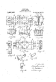
- FIG. 1 a plan view of a sideframe t'rrwith'onehalf of a bolster supported thereon;
- Fig. 3 is a view partly in vertical section and partly in side elevation of the bolster
- Fig. 4 is a plan view of the middle portion of the bolster, the center plate being removed;
- Fig. 5 is a vertical sectional view on the a line A-'A of Fig. 4.;
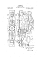
- Fig. 6 is a view of the end wall ofthe' bolster
- Fig. 7 is a side elevationof one end of the bolster; I f
- Fig. 8 is a vertical section on the line 13-43 of Fig. 7; i Fig. 9 is a vertical sectional viewtaken through the middle of the sideframe:
- Fig. 10 is a bottom view of the form of center plate: I
- Fig. 11 is a vertical section thcrethrough on the line D-D of Fig. 10: p
- Fig. 15 is a diagram illustrating the truss construction of the side frame
- v Fig. 1G is a plan view
- -of a slightly modified forin of bolster
- Fig. 17 is a view partly in side eleifation and partly in vertical section of the type of bolster shown in Fig. 16;
- Fig. 18 is a perspective view of one of the bell-cranks employed in the bolster shown in Fig. 17-:
- Fig. 19 is a view of the end walLof the bolster shown in Fig. 17 and Fig. 20 is a side elevationofthe modified side frame used in connection with the bolster shown in Fig-17. 7'
- A designates-the side. framc,which, in its preferred form, as shown in Fig. 2, is cast or otherwiseconstructed with its several panels a each of a triangular shape.
- the upper edge of the side frame is provided at midlength with a notch b, the sides of which-incline dowmvardly-toward each other to form a substantially V-shaped notch, although, as shown in Fig.20, this notch may have a true concave shape, the essential feature being that the sides of the notch shalluincline downwardly toward the center thereof.
- the end of the bolsterB is correspondingly shaped to fit down in this notch, and, in order to prevent the bolster. having any endwise movement with respect to the side frame, the bolster at itszend is provided with depending flanges c'which preferred of the bolster beingslightly less than.
- the center plate 6 is supported resiliently on the bolster by means of coil springs f,
- each pair of lugs is pivotally connected, by a pivot h, one end of a bell-crank '5, the lower ends of these bell-cranks being pivotally connected, respectively, to links j.
- Each of the links is pivotally connected to a wedge-shaped thrust block 70 suitably guided in the bolster.
- Resting on each pair of thrust blocks is a side-bearing-block m, which is suitably guided in the bolster.
- I employ a bol- 'ster of.the I-beam type and cutaway the upper flanges of the beam to receive the side edges of portions .of the center plate, the cut-away portions of the flanges being provided with notches p to receive'and guide the vertical flanges q formed on the center plate.
- Suitable ribs arecast in the center plate and in'the bolster to afford the necessary strength and rigidity.- The springs rest upon a horizontal shelf 1 cast in the bolster, this shelf being supported by a suit able arrangement of ribs 8. underneath it.
- Suitable bosses t are formed on the shelf manner i and the under side of the center plate to maintain the sprmgs in proper position.
- this structure I also employ, as hereinbefore stated, a rounded or concaved notch b for the reception of the similarly shaped end of the bolster, this constructionbeing desirable as compared with the V-notch structure in that it allows a freer rocking movement of the frame with respect to the bolster while at the same time the bolster and the side frames are rigidly locked against independent lateral movement.
- the panels are not arranged in accordance with the triangular scheme shownin the other figures; I prefer the triangular arrangementof panels shown in the other figures because that arrangement provides a truss-like structure in which the vertical load will be transmitted directly to a aw. point of the truss, as shown in diagram in Fig. '15.
- a side bearing for trucks consisting? of a vertically movable side-bearing-block, means for normally resisting the downward thrust of said block, and means operated by the load for positioning said side-bearing block at the predetermined clearance withrespect to the body bolster of the car.
- a side bearing arrangement for trucks consisting of vertically movable side-bearing-blocks, thrust blocks in the bolster against which the side-bearing-blocksnor mally bear, and resilient means operated'by the load for positioning said thrust blocks/ 3.
- a side bearing arrangement for trucks consisting of vertically movable slde-bearing-blocks, thrust blocks in the bolster.
- a side bearing arrangement for trucks consisting of vertically movable side-bearing-blocks, slidable wedge-shaped thrust blocks in the bolster, and means operated by depression of the center bearing for pushing said blocks outwardly to permit the bearing blocks to move downwardly into the bolster.
Description
H. BURRMANN;
RAILWAY cm TRUCK.
APPLICATION FILED APR. l 9, 19 17- v Patented Aug. 14, 1917.
'3 SHEETSSHi-ZET 1.
H. BURRMANN.
RAILWAY CAR TRUCK.
APPLICATION man APR. 19. m7;
a SHEETSSHEET 2.
Patented Aug. 14, 1917 H. BURRMANN, v RAILWAY CAR TRUCK. APPLICATION-FILED'APR.19. 1; 9 l'7.
Patented Aug. 14,1917.
s'sH ETs sHEET UNITEDTSTATES PATENT omen.
HENRY BURRMANN, or DAVENPORT, IOWA.
RAILWAY-CAR TRUCK.
Specification of Letters Patent. Paten fgdl-Aug. 14, 1917.
continuation-in, part of copending application Serial No. 137,109. filed December 15,1916. "This ap licant.
' filed April 19, 1917.
To all whom it may cancer-2i:
Be it known that I, HENRY BURRAIANN, a citizen of the United States of America. and a resident of Davenport, county of sary. resiliency and tie bars or other devices I being arranged to connect" the truck side fra-in'es. In this construction, the lateral thrustsdue to the tendency of the car body to move'laterally on the trucks are trans mitted directly to the side frames of the truck, thereby necessitating the employment of heavy side frames and also the tie bars or other connections above referred to. It is one of the objects of my present invention I to relieve the side frames of the truck greatly 30 snake possible to not .only do away with the tie bars, but also to reduce the weight of the side frames, as more fully heroinafter set forth.
A further object of this invention is to provide the truck with side bearings which will automatically adjust themselves to the proper height in accordance with the load married by the car and which also will cushion the thrusts of the car body when it tilts, thus tending to stabilize it, as more fully hereinafter set forth.
In the drawings- Figure 1 a plan view of a sideframe t'rrwith'onehalf of a bolster supported thereon;
'Fig. 2 "is-a side elevation of the same;
Fig. 3 is a view partly in vertical section and partly in side elevation of the bolster,
one of the side frames being shown in vertb '50 cal section Fig. 4 is a plan view of the middle portion of the bolster, the center plate being removed;
Fig. 5 is a vertical sectional view on the a line A-'A of Fig. 4.;
' Scott, State of Iowa, have invent-ed certain from th se heavy thrusts, so as to thereby Serial No. 163,184.
Fig. 6 is a view of the end wall ofthe' bolster;
Fig. 7 is a side elevationof one end of the bolster; I f
Fig. 8 is a vertical section on the line 13-43 of Fig. 7; i Fig. 9 is a vertical sectional viewtaken through the middle of the sideframe:
Fig. 10 is a bottom view of the form of center plate: I
Fig. 11 is a vertical section thcrethrough on the line D-D of Fig. 10: p
Figs. 12. 13 and Hare perspective views of details hereinafter described; I
Fig. 15 is a diagram illustrating the truss construction of the side frame; v Fig. 1G is a plan view; -of a slightly modified forin of bolster; I
Fig. 17 is a view partly in side eleifation and partly in vertical section of the type of bolster shown in Fig. 16;
Fig. 18 is a perspective view of one of the bell-cranks employed in the bolster shown in Fig. 17-:
Fig. 19 is a view of the end walLof the bolster shown in Fig. 17 and Fig. 20 is a side elevationofthe modified side frame used in connection with the bolster shown in Fig-17. 7'
Referring to the drawings annexed by reference characters, A designates-the side. framc,which, in its preferred form, as shown in Fig. 2, is cast or otherwiseconstructed with its several panels a each of a triangular shape. The upper edge of the side frame is provided at midlength with a notch b, the sides of which-incline dowmvardly-toward each other to form a substantially V-shaped notch, although, as shown in Fig.20, this notch may have a true concave shape, the essential feature being that the sides of the notch shalluincline downwardly toward the center thereof. The end of the bolsterB is correspondingly shaped to fit down in this notch, and, in order to prevent the bolster. having any endwise movement with respect to the side frame, the bolster at itszend is provided with depending flanges c'which preferred of the bolster beingslightly less than. the
distance across the top surfaceof the notch, so that, when the bolster isinengagement with the side frame, there will be a space d between the inclined faces of the bolster and the similarly inclined faces of the notch.
With this construction, gravity alone will be sufficient to hold the bolster in place on the side frames, depending flanges serving to prevent the bolster moving end-wisely I with respect to the side frame. It will be observed also that by reason of employment of the inclined=wall notch and the similarly shaped bolster end, a certain amount of flexibility is provided between the side frame and the bolster, to allow a slight rocking movement of the side frame while running on an uneven track.
The center plate 6 is supported resiliently on the bolster by means of coil springs f,
y or in any other suitable manner, and in the form shown in Figs. 1, 2 and 3 it is provided with two pairs of lugs g at each end. Between. each pair of lugs is pivotally connected, by a pivot h, one end of a bell-crank '5, the lower ends of these bell-cranks being pivotally connected, respectively, to links j. Each of the links is pivotally connected to a wedge-shaped thrust block 70 suitably guided in the bolster. Resting on each pair of thrust blocks is a side-bearing-block m, which is suitably guided in the bolster. With this construction, it will be observed that when the car is weighted and the center plate depressed, the wedges 7a will be pushed toward the respective ends of the bolster and thus allow the bearing-blocks m to descend into i the bolster a distance depending on the dis- .wedges is are confined and guided within a pocket 0 formed in the ends of the bolster. The center plate 0 may be supported and guided in any suitable manner, but I prefer the construction shown in Figs. 3, 4:, 5, 10 and 11. In this structure, I employ a bol- 'ster of.the I-beam type and cutaway the upper flanges of the beam to receive the side edges of portions .of the center plate, the cut-away portions of the flanges being provided with notches p to receive'and guide the vertical flanges q formed on the center plate. Suitable ribs arecast in the center plate and in'the bolster to afford the necessary strength and rigidity.- The springs rest upon a horizontal shelf 1 cast in the bolster, this shelf being supported by a suit able arrangement of ribs 8. underneath it.- Suitable bosses t are formed on the shelf manner i and the under side of the center plate to maintain the sprmgs in proper position.
It will be observed also that tlle top flanges of the I-beani are cut out at ti) receive the bell-cranks z and suitable lug or ears '0 are cast on the upper face of the ange for the reception of the pivot w of ti e bell-cranln It will be observed also that th, hole in the bell-crank through which pivo h extends is elongated to form a slot; t is provides the necessary lost motion between the bellcrank and the center plate. .lt will be understood, however, that these features are all of minor importance and that, therefore, they may be greatly va iedwithout departing from the spirit of 15y invention.
On sheet 3 of the drawings, have shown an. arrangement whereby I employ but a single bell-crank i at-each side of the center i plate and a single thrust wedge 7a. In tnis construction also, I employ a ll-beam or box-beam instead of the I-beam type shown 1 1n the other figures. In this U-beam bolster type, the center plate 6 fits down between the flanges of the beam and is thereby guided and steadied. \Vith this structure I also employ, as hereinbefore stated, a rounded or concaved notch b for the reception of the similarly shaped end of the bolster, this constructionbeing desirable as compared with the V-notch structure in that it allows a freer rocking movement of the frame with respect to the bolster while at the same time the bolster and the side frames are rigidly locked against independent lateral movement. In the type of side frame I have shown on sheet 3, the panels are not arranged in accordance with the triangular scheme shownin the other figures; I prefer the triangular arrangementof panels shown in the other figures because that arrangement provides a truss-like structure in which the vertical load will be transmitted directly to a aw. point of the truss, as shown in diagram in Fig. '15.
It will be; observed that'in the truss sideframe shown on sheet 1, the bolster-end? being rigid, the load will/be transmitted directly to the .apex of the central triangle so that the upright bars of this triangle will l e subjected to compression strain only, win the basebar of the triangle will be subjected to tension strain only. The lower bars of the two larger end-triangles will be subjected to tension strain only, while the -upper bars of these triangles will be subjected to COIIIPIGS. sion strain only. lhe top bars of the two flanking small triangles will be subjected to compression strain only, while the two vertical bars of the small triangles will be subj ected to tension strain only. In this way, I avoid entirely triangles to a bending or transverse breakin strain, so that with a given weight I gain very materially in the strength of the subjecting any bars of the side frames; in fact, with this true truss construction of side frame, I can produce a side frame with the weight'75 to 100 pounds less than the ordinary type of the same capacity and at the same time reduce the stresses on the members.
The nature and scope of the invention having been thus indicated and its preferred embodiment having been specifically described, what is claimed as new is:
1. A side bearing for trucks, consisting? of a vertically movable side-bearing-block, means for normally resisting the downward thrust of said block, and means operated by the load for positioning said side-bearing block at the predetermined clearance withrespect to the body bolster of the car.
2. A side bearing arrangement for trucks, consisting of vertically movable side-bearing-blocks, thrust blocks in the bolster against which the side-bearing-blocksnor mally bear, and resilient means operated'by the load for positioning said thrust blocks/ 3. A side bearing arrangement for trucks, consisting of vertically movable slde-bearing-blocks, thrust blocks in the bolster.
against which the side-bearing-blocks normally bear, and means operated by the load for positioning said thrust blocks, said means embodying a resiliently supported center bearing for the car body.
4. A side bearing arrangement for trucks, consisting of vertically movable side-bearing-blocks, slidable wedge-shaped thrust blocks in the bolster, and means operated by depression of the center bearing for pushing said blocks outwardly to permit the bearing blocks to move downwardly into the bolster. v
5. The structure defined in claim 4, said means consisting of bell-cranks connected to the center bearing and links connecting these cranks to the thrust blocks.
6. The combination with a side frame having a notch in its upper edge said notchhaving its walls inclined downwardly toward each other, of a bolster having its end shaped to fit down in said notch and rest therein, said bolster being provided with 'of the side frames being provided with a seat for the bolster and one of thetriangles bein arranged centrally under said seat and having its apex supporting said seat.
In testimony whereof I hereunto afiix my signature.
HENRY BURRMANN.
Priority Applications (1)
| Application Number | Priority Date | Filing Date | Title |
|---|---|---|---|
| US16318417A US1237167A (en) | 1917-04-19 | 1917-04-19 | Railway-car truck. |
Applications Claiming Priority (1)
| Application Number | Priority Date | Filing Date | Title |
|---|---|---|---|
| US16318417A US1237167A (en) | 1917-04-19 | 1917-04-19 | Railway-car truck. |
Publications (1)
| Publication Number | Publication Date |
|---|---|
| US1237167A true US1237167A (en) | 1917-08-14 |
Family
ID=3304986
Family Applications (1)
| Application Number | Title | Priority Date | Filing Date |
|---|---|---|---|
| US16318417A Expired - Lifetime US1237167A (en) | 1917-04-19 | 1917-04-19 | Railway-car truck. |
Country Status (1)
| Country | Link |
|---|---|
| US (1) | US1237167A (en) |
Cited By (2)
| Publication number | Priority date | Publication date | Assignee | Title |
|---|---|---|---|---|
| US2424001A (en) * | 1943-10-30 | 1947-07-15 | Jay R Sheesley | Railway car truck |
| US3244462A (en) * | 1963-09-20 | 1966-04-05 | Standard Car Truck Co | Resilient side bearings for railroad cars |
-
1917
- 1917-04-19 US US16318417A patent/US1237167A/en not_active Expired - Lifetime
Cited By (2)
| Publication number | Priority date | Publication date | Assignee | Title |
|---|---|---|---|---|
| US2424001A (en) * | 1943-10-30 | 1947-07-15 | Jay R Sheesley | Railway car truck |
| US3244462A (en) * | 1963-09-20 | 1966-04-05 | Standard Car Truck Co | Resilient side bearings for railroad cars |
Similar Documents
| Publication | Publication Date | Title |
|---|---|---|
| US1237167A (en) | Railway-car truck. | |
| US1237166A (en) | Railway-car truck. | |
| US2076503A (en) | Articulated car | |
| US717304A (en) | Car-truck. | |
| US1879549A (en) | Car truck | |
| US3447483A (en) | Resiliently centered railway locomotive truck | |
| US799606A (en) | Car-truck. | |
| US1907384A (en) | Inboard truck with lateral motion means | |
| US972286A (en) | Railway car and truck. | |
| US2044576A (en) | Lateral restraint device | |
| US710637A (en) | Car-truck. | |
| US2956516A (en) | Railway vehicle side bearing structure | |
| US2594079A (en) | Inboard railway truck | |
| US2011190A (en) | Railway truck | |
| US3015285A (en) | Snubbed railway truck | |
| US3392680A (en) | Railway motor truck with bolster resiliently mounted | |
| US694385A (en) | Bolster for railway-cars. | |
| US726500A (en) | Car truck and bolster. | |
| US730283A (en) | Bolster. | |
| US849193A (en) | Swing-motion truck. | |
| US728583A (en) | Railway-car truck. | |
| US738773A (en) | Car-truck. | |
| US1055656A (en) | Railway-car bolster. | |
| US990572A (en) | Center-sill construction. | |
| US773674A (en) | Bolster. |