US1237120A - Automobile-signal. - Google Patents
Automobile-signal. Download PDFInfo
- Publication number
- US1237120A US1237120A US13265716A US13265716A US1237120A US 1237120 A US1237120 A US 1237120A US 13265716 A US13265716 A US 13265716A US 13265716 A US13265716 A US 13265716A US 1237120 A US1237120 A US 1237120A
- Authority
- US
- United States
- Prior art keywords
- arm
- signal
- shaft
- trunnion
- cap plate
- Prior art date
- Legal status (The legal status is an assumption and is not a legal conclusion. Google has not performed a legal analysis and makes no representation as to the accuracy of the status listed.)
- Expired - Lifetime
Links
- 230000008093 supporting effect Effects 0.000 description 11
- 238000010276 construction Methods 0.000 description 2
- SUBDBMMJDZJVOS-UHFFFAOYSA-N 5-methoxy-2-{[(4-methoxy-3,5-dimethylpyridin-2-yl)methyl]sulfinyl}-1H-benzimidazole Chemical compound N=1C2=CC(OC)=CC=C2NC=1S(=O)CC1=NC=C(C)C(OC)=C1C SUBDBMMJDZJVOS-UHFFFAOYSA-N 0.000 description 1
- 102000004726 Connectin Human genes 0.000 description 1
- 108010002947 Connectin Proteins 0.000 description 1
- 230000015572 biosynthetic process Effects 0.000 description 1
- 239000000789 fastener Substances 0.000 description 1
- 239000000463 material Substances 0.000 description 1
- 238000000034 method Methods 0.000 description 1
- 238000006748 scratching Methods 0.000 description 1
- 230000002393 scratching effect Effects 0.000 description 1
Images
Classifications
-
- B—PERFORMING OPERATIONS; TRANSPORTING
- B60—VEHICLES IN GENERAL
- B60Q—ARRANGEMENT OF SIGNALLING OR LIGHTING DEVICES, THE MOUNTING OR SUPPORTING THEREOF OR CIRCUITS THEREFOR, FOR VEHICLES IN GENERAL
- B60Q1/00—Arrangement of optical signalling or lighting devices, the mounting or supporting thereof or circuits therefor
- B60Q1/26—Arrangement of optical signalling or lighting devices, the mounting or supporting thereof or circuits therefor the devices being primarily intended to indicate the vehicle, or parts thereof, or to give signals, to other traffic
- B60Q1/34—Arrangement of optical signalling or lighting devices, the mounting or supporting thereof or circuits therefor the devices being primarily intended to indicate the vehicle, or parts thereof, or to give signals, to other traffic for indicating change of drive direction
Definitions
- bracket for supporting the signal arm on "the motor vehicle, and the signal arm being so journaled to said bracket in order to permit itsmanipulation in not only a quick and simple manner,'but to lock such signal arm 3051i either an extended or closed position.
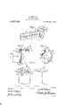
- Figure 1 is a perspective view of the signal s own detached from a car; 7 Fig. 2 is a vertical section taken on line 22 of Fig. 1;
- Fig. 3 is a side elevation of a portion of a car showing the signal attached thereto; and Fig. 4 is a bottom plan view of the cap plate showing the operating lever assembledthereon and the socket being shown in section.
- 5 indicates the body portion of a motor vehiclevhaving mounted preferably on the front door thereof a direction signal, denoted generally by the character 6.
- bracket 8 is constructed of any suitable material and constituting a vertical supporting arm 9 provided with openings 10 through which extend suitable fas-- teners 11 for connecting the supporting arm of the bracket to the exterior or front face of the door of the motor vehicle.
- the extreme lower end of the supporting arm 9 is bent in a direction laterally to the outer face thereof to provide an angular lip 12 having a centrally located circular bearing opening 13.
- the opposite or upper end of the supporting arm is bent in a lateral direction from the opposite face thereof to provide an enlarged semi-circular base plate 1i adapted upon the operative position-of the signal, to
- This bracket 8 further embodies a arm 20 of the signal is a shaft 21 having provided on its lower end a cylindrical trunnion 22-, while provided on the upper end of the shaft is a squared trunnion 23, and as is apparent from the drawing, when the signal arm is mounted on the bracket, the circular trunnion 22 of the shaft is journaled, in the bearing opening 13 ofthe lip 12 While the square trunnion 23 of the shaft projects in the bearing opening 19 of the socket 17 and engages in a slot 24: formed in the head 25 of an operating handle 26.
- the head extends within the socket 17 and owing to the hollow formation of the cap .plate 15 will ac-.
- a vehicle signal embodying a support ing arm provided at one end with a lip extending laterally from one face of the supporting arm, a base plate provided on the opposite end of the supporting arm and extending ina lateral direction from the opposite face of said arm, a hollow cap plate provided with an arcuate slot and a socket formed with a bearing opening, meansfor detachably connecting the cap plate umn the base plate, an in eating arm provided with a shaft having a circular trunnion and a squared trunnion, the trunnions of said shaft being journaled for rotary movement in the bearing openings of said lip and socket, and means operatively connected to the squared trunnion of said shaft and operating in the arcuate slot of said cap plate for imparting movement to said indicating arm, and means formed on the'inner face of the cap plate and at opposite extremities of said arcuate slot for retaining the indicatin arm in either a locked extended or a lod lied closed position.
- a vehicle-signal comprising a supporting arm provided at one end with a lip extending laterally from one face of the supporting arm, a base plate provided on the opposite end of the supporting arm and extending in a lateral direction from the opposite face of said arm, a hollow cap plate provided with an arcuate slot and a socket formed with a bearing opening, means for detachably connectin the cap plate upon the base plate, an in icating arm provided with a shaft having a circular trunnion and a squared trunnion, the trunnions of said shaft being journaled for rotary movement in the bearing openings of said lip and socket, and means operatively connected to the squared trunnion of said shaft and operating in the arcuate slot of said cap plate for imparting movement to said indicating arm, and beveled lugs formed on the inner face of the cap plate and at opposite extremities of said arcuate slot for retaining the indicating arm in either a locked extended or a locked closed position.
Landscapes
- Engineering & Computer Science (AREA)
- Mechanical Engineering (AREA)
- Lock And Its Accessories (AREA)
Description
A. STURTEVANT.
AUTOMOBILE SIGNAL.
APPLICATION FILED NOV. 2|. 19m.
PatentedAug. 14, 1917.
AMSZZUZZVWZZJNYEETOR-II I ATTo R N EY WITNESSES V UNITED.
ARTHUR STUBTEVANT, OF SANTA BARBARA, CALIFORNIA.
' AUTOMOBILE-SIGNAL.
To all whom it may concern Be it known that I, ARTHUR STURTEVANT, a citizen of the United States, residing at Santa Barbara, in the county of Santa Barbare. and State of California, have invented new, and useful Improvements in Auto mobile-Signals, of whlch the following 15 a specification 'llhe present invention contemplates the production of an automobile slgnal f such construction to adapt its manipulation in a 'quickand easy manner, in order that the driver of the car ahead may g'I-Ve warning to the-driver ofthe car in the rear that the machine bearing the signal is about to make a turn either to the right or to the left, the signal alarm being self-retaining in order that bfoth hands of the operator'may' be free for opei'hting the machine, and further during unfavorable weather conditions will not necessitate the operator extending his arm exter'i'orlyof the car to indicate the directio of the travel of the car. urthermore, use is made of a novel type 25. of bracket for supporting the signal arm on "the motor vehicle, and the signal arm being so journaled to said bracket in order to permit itsmanipulation in not only a quick and simple manner,'but to lock such signal arm 3051i either an extended or closed position.
With the above and other objects in view, the invention consists in the novel features, details ofconstruction and combination of parts which will hereinafter be more fully set forth, illustrated in the accompanying drawing and pointed out in the appended claims. v
Figure 1 is a perspective view of the signal s own detached from a car; 7 Fig. 2 is a vertical section taken on line 22 of Fig. 1;
Fig. 3 is a side elevation of a portion of a car showing the signal attached thereto; and Fig. 4 is a bottom plan view of the cap plate showing the operating lever assembledthereon and the socket being shown in section.
Referring more particularly to the accompanying drawing, in which like characters of reference-refer to corresponding partsin the several views, 5 indicates the body portion of a motor vehiclevhaving mounted preferably on the front door thereof a direction signal, denoted generally by the character 6. The signal arm or indicator 7 of door.
Specification of Letters Patent. Patented Aug. 14:, 191'?- Application filed November 21, 1916. Serial No. 132,657. I
the signal is operatively supported on the car through'the medium of a novel type of bracket 8. This bracket 8 is constructed of any suitable material and constituting a vertical supporting arm 9 provided with openings 10 through which extend suitable fas-- teners 11 for connecting the supporting arm of the bracket to the exterior or front face of the door of the motor vehicle. The extreme lower end of the supporting arm 9 is bent in a direction laterally to the outer face thereof to provide an angular lip 12 having a centrally located circular bearing opening 13. The opposite or upper end of the supporting arm is bent in a lateral direction from the opposite face thereof to provide an enlarged semi-circular base plate 1i adapted upon the operative position-of the signal, to
7 rest upon the upper edge of the door of the motor vehicle and extend inwardly of said formed in the bottom wall 18 thereof a cylindricalbearing opening 19. Provided on the rear transverse edge of the indicating This bracket 8 further embodies a arm 20 of the signal is a shaft 21 having provided on its lower end a cylindrical trunnion 22-, while provided on the upper end of the shaft is a squared trunnion 23, and as is apparent from the drawing, when the signal arm is mounted on the bracket, the circular trunnion 22 of the shaft is journaled, in the bearing opening 13 ofthe lip 12 While the square trunnion 23 of the shaft projects in the bearing opening 19 of the socket 17 and engages in a slot 24: formed in the head 25 of an operating handle 26. In order to allow of this connection of the shaft of the signal arm with the head 25 of the operating handle, it is obvious that the head extends within the socket 17 and owing to the hollow formation of the cap .plate 15 will ac-.
commodate the arm 27 of the operating lever and allow the operator, upon grasping the knob 28, to move the operating lever in an arcuate path. This movement of the lever is caused by the provision in the top wall 29 of the cap plate of an arcuate slot 30. Formed integral with the inner face of the top wall 29 of said cap plate and flush with v, neeaiaoone of the walls forming the arcuate slot 30, and at the opposite extremities of said slot is a pair of beveled lugs 31, consequently upon movement of the knob 28 to one extreme end of the arcuate slot, the arm 27 of the operating lever will ride over one of the lugs 31 and cause the signal to be locked in an open position, while upon the movement of the knob 28 to the opposite extreme end ment of suitable fasteners such as screws or the like, designated by the character 32. It is to be further stated in order to prevent the indicating arm from scratching or mutilating the door of the vehicle when the same assumes a closed position, use is made of a plate 33.
From the foregoing description, taken in connection with the accompanying drawing, the advantages of construction and the method of operation will be readily apparent to those skilled in the art to whichthe invention relates, and while I have described the principles of operation of the invention, together with the device which I now-consider to be the best embodiment thereof, I desire to have it understood that the device shown is merely illustrative, and that such changes may be made when desired as are within the scope of the appended claims.
What is claimed as new, is:
1. A vehicle signal embodying a support ing arm provided at one end with a lip extending laterally from one face of the supporting arm, a base plate provided on the opposite end of the supporting arm and extending ina lateral direction from the opposite face of said arm, a hollow cap plate provided with an arcuate slot and a socket formed with a bearing opening, meansfor detachably connecting the cap plate umn the base plate, an in eating arm provided with a shaft having a circular trunnion and a squared trunnion, the trunnions of said shaft being journaled for rotary movement in the bearing openings of said lip and socket, and means operatively connected to the squared trunnion of said shaft and operating in the arcuate slot of said cap plate for imparting movement to said indicating arm, and means formed on the'inner face of the cap plate and at opposite extremities of said arcuate slot for retaining the indicatin arm in either a locked extended or a lod lied closed position. I v
2. A vehicle-signal comprising a supporting arm provided at one end with a lip extending laterally from one face of the supporting arm, a base plate provided on the opposite end of the supporting arm and extending in a lateral direction from the opposite face of said arm, a hollow cap plate provided with an arcuate slot and a socket formed with a bearing opening, means for detachably connectin the cap plate upon the base plate, an in icating arm provided with a shaft having a circular trunnion and a squared trunnion, the trunnions of said shaft being journaled for rotary movement in the bearing openings of said lip and socket, and means operatively connected to the squared trunnion of said shaft and operating in the arcuate slot of said cap plate for imparting movement to said indicating arm, and beveled lugs formed on the inner face of the cap plate and at opposite extremities of said arcuate slot for retaining the indicating arm in either a locked extended or a locked closed position.
In testimony whereof I affix my signature.
ARTHUR STURTEVANT.
Copies of this patent may be obtainedror five cents each, by addressing the Commissioner of Patents,
Washington, D. 6. a
Priority Applications (1)
| Application Number | Priority Date | Filing Date | Title |
|---|---|---|---|
| US13265716A US1237120A (en) | 1916-11-21 | 1916-11-21 | Automobile-signal. |
Applications Claiming Priority (1)
| Application Number | Priority Date | Filing Date | Title |
|---|---|---|---|
| US13265716A US1237120A (en) | 1916-11-21 | 1916-11-21 | Automobile-signal. |
Publications (1)
| Publication Number | Publication Date |
|---|---|
| US1237120A true US1237120A (en) | 1917-08-14 |
Family
ID=3304939
Family Applications (1)
| Application Number | Title | Priority Date | Filing Date |
|---|---|---|---|
| US13265716A Expired - Lifetime US1237120A (en) | 1916-11-21 | 1916-11-21 | Automobile-signal. |
Country Status (1)
| Country | Link |
|---|---|
| US (1) | US1237120A (en) |
-
1916
- 1916-11-21 US US13265716A patent/US1237120A/en not_active Expired - Lifetime
Similar Documents
| Publication | Publication Date | Title |
|---|---|---|
| US2259614A (en) | Clearance indicator for automobiles | |
| US1237120A (en) | Automobile-signal. | |
| US1336489A (en) | Signal device | |
| US1277920A (en) | Direction-indicator for vehicles. | |
| US1250313A (en) | Automobile-lock. | |
| US1341032A (en) | William h | |
| US1340081A (en) | Direction-indicator | |
| US1316821A (en) | Planoobaph co | |
| US1225022A (en) | Automobile-signal. | |
| US1303240A (en) | Automobile-jack | |
| US1437533A (en) | Vehicle signal | |
| US1264162A (en) | Direction-indicator. | |
| US2530666A (en) | Vehicle ventilator operator | |
| US1323118A (en) | Automobile-sigbtai | |
| US1030027A (en) | Vehicle-signal. | |
| US1283263A (en) | Auto-signal. | |
| US1488280A (en) | Motor-vehicle signal | |
| US1408227A (en) | Automobile safety appliance | |
| US1291937A (en) | Steering device for automobiles. | |
| US1577707A (en) | Signaling device for motor vehicles | |
| US1415081A (en) | Thief alarm for automobiles | |
| US1220315A (en) | Locking device for automobiles. | |
| US1311257A (en) | Michael edwakd wilboi | |
| US1232995A (en) | Direction-indicating signal for motor-vehicles. | |
| US1337709A (en) | Vehicle-lock |