US123710A - Improvement in hay-tedders - Google Patents
Improvement in hay-tedders Download PDFInfo
- Publication number
- US123710A US123710A US123710DA US123710A US 123710 A US123710 A US 123710A US 123710D A US123710D A US 123710DA US 123710 A US123710 A US 123710A
- Authority
- US
- United States
- Prior art keywords
- axle
- pinion
- teeth
- hay
- bushing
- Prior art date
- Legal status (The legal status is an assumption and is not a legal conclusion. Google has not performed a legal analysis and makes no representation as to the accuracy of the status listed.)
- Expired - Lifetime
Links
- 230000006872 improvement Effects 0.000 title description 6
- 230000008859 change Effects 0.000 description 3
- 239000002184 metal Substances 0.000 description 3
- 238000010276 construction Methods 0.000 description 2
- 230000008901 benefit Effects 0.000 description 1
- 230000007423 decrease Effects 0.000 description 1
- 210000003746 feather Anatomy 0.000 description 1
- 230000007246 mechanism Effects 0.000 description 1
- NJPPVKZQTLUDBO-UHFFFAOYSA-N novaluron Chemical compound C1=C(Cl)C(OC(F)(F)C(OC(F)(F)F)F)=CC=C1NC(=O)NC(=O)C1=C(F)C=CC=C1F NJPPVKZQTLUDBO-UHFFFAOYSA-N 0.000 description 1
- 239000011435 rock Substances 0.000 description 1
- 230000007480 spreading Effects 0.000 description 1
Images


Classifications
-
- A—HUMAN NECESSITIES
- A01—AGRICULTURE; FORESTRY; ANIMAL HUSBANDRY; HUNTING; TRAPPING; FISHING
- A01D—HARVESTING; MOWING
- A01D78/00—Haymakers with tines moving with respect to the machine
- A01D78/08—Haymakers with tines moving with respect to the machine with tine-carrying rotary heads or wheels
- A01D78/10—Haymakers with tines moving with respect to the machine with tine-carrying rotary heads or wheels the tines rotating about a substantially vertical axis
- A01D78/1007—Arrangements to facilitate transportation specially adapted therefor
- A01D78/1014—Folding frames
Definitions
- FIG. 1 is a plan View of the upper side of my device.
- Fig. 2 is a side elevation of the same with the inner traction-wheel removed.
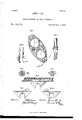
- Fig. 3 is an enlarged end elevation of the reel containing the pivoted tine-heads.
- Fig. 4 is a like view of the driving pinion and pawl for imparting motion to said reel.
- Fig. 5 is a side elevation of the adjustable sun gear for rotating said tine-heads.
- Fig. 6 is a like view of the outer side of the pedestal-box with its rotating eccentric jaw for connecting the ted- I der-frame to or upon the axle.
- Figs. 7 and 8 are similar views of said pedestal from its inner side, showing the'different positions of the eccentric jaw.
- Fig. 9 is an enlarged plan view of the journal of the axle; and
- Fig. 10 is a front and a side elevation of the lever for con-' trolling the vertical adjustment of the tedder. Lettersof like name and kind refer to like parts in each of the figures.
- Y My invention is an improvement in hay-tedders intended for use upon or in combination with horse hay-rakes,or other similar wheeled machines; and it consists principally in the means employed for connecting the tedderfi'ame to or upon the axle, substantially as and for the purpose hereinafter set forth. It further consists in the employment of eccentrio gearing for imparting to said tedder-teeth a variable rotary movement with relation to the reel, substantially as is hereinafter shown.
- A represents the axle
- B the traction-wheels
- G the shafts of an ordinary horse hay-rake, the latter of which are connected together forward of said axle, by means of a crossbar, D, between which said axle and shafts is secured a foot- 7 board, E.
- a rake-head, F containing a series of curvedteeth, G, and provided with a hand-lever, H, for tripping the flame, all of usual construction.
- the 'tedder-frame is composed of two side-pieces, I, secured together in parallel lines by means of two cross-bars, K and L, attached respectively to their center and front ends, leaving a space at the rear of the frame for the tedder-reel, which, as seen in Figs. 1 and 2.
- a central shaft, M pivoted within suitable boxes N secured to or upon the lower side of the side pieces I, and having keyed upon its ends, immediately inside of said pieces, two heads, 0. .Pivoted within the heads 0, near their outer ends, are two tine-heads, 1?, having each a series of short curved teeth, Q, of usual construction, which teeth are relatively arranged so as to break joints or overlap each other.
- the reel iscaused to revolve within the frame by means of pinions R placed upon its outer ends and communicating through suitable gearing with the traction-wheels, while the tine-heads are caused to revolve within said reel, so as to feather their teeth by means of a pinion, S, attached to the inner end of one of the boxes N, and meshing with two gear, T. pivoted upon opposite sides thereof to the head 0, which gear, in turn, mesh with two pinions, U, attached to the projecting ends of the rake-heads P, the whole forming what is known as a sun and planet gearing.
- the relative proportions of the pinions and gears above described are such as to cause the rake-teeth to maintain a general vertical position but, in order that said teeth may work to the best possible advantage, it is necessary that. they should strike the ground at a low angle, which angle should change as said teeth sweep to the rear, until, at the time of their leaving the hay, their general inclination should be turned upward and rearward.
- the pinions in the form of eccentrics and give to the gears a cam shape, having as many faces or depressions upon their toothed peripheries, as said peripheries rep-,-
- the radial adjustment of the tine-heads and teeth is effected by pivoting the pinion S upon the box N, and providing a suitable pawl to engage with and secure said pinion in place.
- the pawl used, V has a general crescent shape, and is pivoted at its center upon said box N with its concave edge toward said pinion, in which position a flat spring, o, is caused to press upward against its upper end, so as to bring its lower end against said pinion and cause an upward projecting spur, 02, attached thereto to engage with the teeth of the pinion or with suitable depressions formed thereon.
- Bypressing downward upon the upper end of the pawl its lower end will be released from engagement with the pinion and permit the same to be rotated, 'as desired.
- this pinion As the principal use made of the adjustability of this pinion will be to enable the teeth to be turned into line with the heads, so as to cause the device to occupy less room when not in use, I provide within the face of said pinion a groove, pro vided within its lower side with suitable teeth for engagement with the spur o and having a sufficient length only to permit said pinion to move the required distance, by which means it is only necessary to release and revolve the same until the detent strikes against either end of said slot in order to adjust the teeth for use or for storing the machine.
- the pinion R is pivoted loosely upon the shaft M, and caused to engage therewith when revolved forward by the following-described means:
- One side of the pinion is recessed out so as to receive a corresponding metal collar, m, attached to the shaft, which collar has upon or within opposite sides two semicircular recesses which receive and contain each a similar-shaped detent, 0c.
- the detent m is pivoted at one end to the collar m, while its opposite end is free to swing outward, so as to engage with suitable notches 4" provided around the interior of the recess within the pinion B when said pinion is revolved in one direction, while, in an opposite direction, said detent will be pressed by and slide over said teeth.
- the device thus constructed is applied to the hay-rake by means of two pedestal-boxes, W, attached to and projecting downward from the lower side of the side pieces I, and fitting into corresponding bearings X provided upon the axles immediately inside the wheels, the lower side of said boxes being open, so as to permit them to be readily passed over or removed from said bearings.
- I enlarge the opening within the pedestal-box W and fit loosely within the same a bushing, Y, having upon one side an opening corresponding to the diameter of the bearing X, which bushing has attached to one end a plate,'-Z, by means of g which it may be rotated within its opening.
- the periphery and interior of the bushing although each formed upon a circle, have not a common center, but have such relative arrangement as to give to said bushing a crescent-shape, its thickest part being at its upper side, whence it regularly decreases in thickness until, at the lateral opening, its inner and outer surfaces come together.
- the efiect of such an eccentric shape of the bushing is to cause the tedder-frame to move forward or back as said bushing is revolved upon the axle, the object of which will be hereinafter explained.
- the bushing is caused to rotate within the pedestal-box by means of a lever, A, pivoted at one end to the side-rail I, and having attached between said pivoted end and its upper or free end a connecting-bar, B, the opposite end of which is, in turn, pivoted upon the upper end of the plate Z, so that as said lever is thrown forward or back, as shown in Figs. 2 and 6, the bushing will be rotated and the tedder-frame looked upon or released from the axle.
- a lever, A pivoted at one end to the side-rail I, and having attached between said pivoted end and its upper or free end a connecting-bar, B, the opposite end of which is, in turn, pivoted upon the upper end of the plate Z, so that as said lever is thrown forward or back, as shown in Figs. 2 and 6, the bushing will be rotated and the tedder-frame looked upon or released from the axle.
- eachtra'ction-wheelB Attached to or upon the inner face of eachtra'ction-wheelB is a spur-gear, O, which meshes with a smaller gear, D, and the latter, in turn, with the pinion R, and thereby communicates the motion of said traction-wheels to the reel and pivoted tine-heads.
- the relative arrangement of the gears O and D cause them to mesh together only when the bushing Y is'turned forward so as to correspondingly move the tedder-frame and lock it upon or to the axle, in consequence of which said gearing are thrown out of engagement by turning said bushing partly or wholly to the rear, such result being sought by giving the latter its eccentric form.
- the tedder-frame Being attached to the axle only at or by the pedestal-boxes, the tedder-frame is free to rock upon the axle, so as to raise or lower its rear end, and thereby adapt the operating mechanism to thevariable surface of the ground and the quantity and weight of the hay.
- I employ a lever, E ,”provided at its lower end with an outward and upward projecting arm, loosely pivoted at said end to or upon the footboard E, so that said arm shall pass beneath the cross-bar L and into a suitable metal loop or guide, I, attached upon the same. If now the upper end of the lever be moved to the front or rear, the tedder-frame will be correspondingly rocked upon the aXle and its rear end elevated or-depressed.
- a detent, e, projecting laterally outward from said lever engages with said notched segment, and secures the relative positions of the same and the lever, except when the latter is moved sidewise sufficiently to disengage said detent, after which said lever may be carried to the front orrear, as is desired.
- the detent is held in engagement with the quadrant by means of a spring, H, secured to the lever, and from thence projecting outward and downward with its free end bearing against the outer face of said quadrant.
- a metal strip, 1, projecting horizontally outward from said lever, and provided with a suitable slot for the passage of said spring holds the latter in position, and
Landscapes
- Life Sciences & Earth Sciences (AREA)
- Environmental Sciences (AREA)
- Transmission Devices (AREA)
Description
Sheet 1.
2 Shuts.
JAMES LEE.
Improvement in My Tedders.
Patented Feb. 13,1872;
wwh I W W a I. V A i v", m n m.
2 Shegta. Shawl 2..
JAMES LEE I Improvement in; Hay Teddrs.
Nb.. 123,710. Patented Feb-.13,l872.
UNITED. STATES JAMES LEE, OF POTTSTOWN, PENN SYLVANIA.-
IMPROVEMENT IN HAV-TEDDERS.
Specification forming part of Letters Patent No. 123,710, dated February 13, 1872.
To all whom it may concern Be it known that I, JAMES LEE, of Pottstown, in the county of Montgomery and in the State of Pennsylvania, have invented certain new and useful Improvements in Hay-Tedders; and do hereby declare that the followingis a full,'clear, and exact description thereof, reference being had to the accompanying drawing making a part of this specification, in which- Figure 1 is a plan View of the upper side of my device. Fig. 2 is a side elevation of the same with the inner traction-wheel removed. Fig. 3 is an enlarged end elevation of the reel containing the pivoted tine-heads. Fig. 4 is a like view of the driving pinion and pawl for imparting motion to said reel. Fig. 5 is a side elevation of the adjustable sun gear for rotating said tine-heads. Fig. 6 is a like view of the outer side of the pedestal-box with its rotating eccentric jaw for connecting the ted- I der-frame to or upon the axle. Figs. 7 and 8 are similar views of said pedestal from its inner side, showing the'different positions of the eccentric jaw. Fig. 9 is an enlarged plan view of the journal of the axle; and Fig. 10 is a front and a side elevation of the lever for con-' trolling the vertical adjustment of the tedder. Lettersof like name and kind refer to like parts in each of the figures. Y My invention is an improvement in hay-tedders intended for use upon or in combination with horse hay-rakes,or other similar wheeled machines; and it consists principally in the means employed for connecting the tedderfi'ame to or upon the axle, substantially as and for the purpose hereinafter set forth. It further consists in the employment of eccentrio gearing for imparting to said tedder-teeth a variable rotary movement with relation to the reel, substantially as is hereinafter shown. In the annexed drawing, A represents the axle, B the traction-wheels, and G the shafts of an ordinary horse hay-rake, the latter of which are connected together forward of said axle, by means of a crossbar, D, between which said axle and shafts is secured a foot- 7 board, E. Pivoted to or upon the axle is a rake-head, F, containing a series of curvedteeth, G, and provided with a hand-lever, H, for tripping the flame, all of usual construction. The 'tedder-frame is composed of two side-pieces, I, secured together in parallel lines by means of two cross-bars, K and L, attached respectively to their center and front ends, leaving a space at the rear of the frame for the tedder-reel, which, as seen in Figs. 1 and 2.
consists of a central shaft, M, pivoted within suitable boxes N secured to or upon the lower side of the side pieces I, and having keyed upon its ends, immediately inside of said pieces, two heads, 0. .Pivoted within the heads 0, near their outer ends, are two tine-heads, 1?, having each a series of short curved teeth, Q, of usual construction, which teeth are relatively arranged so as to break joints or overlap each other. The reel iscaused to revolve within the frame by means of pinions R placed upon its outer ends and communicating through suitable gearing with the traction-wheels, while the tine-heads are caused to revolve within said reel, so as to feather their teeth by means of a pinion, S, attached to the inner end of one of the boxes N, and meshing with two gear, T. pivoted upon opposite sides thereof to the head 0, which gear, in turn, mesh with two pinions, U, attached to the projecting ends of the rake-heads P, the whole forming what is known as a sun and planet gearing.
The relative proportions of the pinions and gears above described are such as to cause the rake-teeth to maintain a general vertical position but, in order that said teeth may work to the best possible advantage, it is necessary that. they should strike the ground at a low angle, which angle should change as said teeth sweep to the rear, until, at the time of their leaving the hay, their general inclination should be turned upward and rearward. In order to produce such variable motion of the teeth I construct the pinions in the form of eccentrics, and give to the gears a cam shape, having as many faces or depressions upon their toothed peripheries, as said peripheries rep-,-
resent complete revolutions of said pinions. As thus constructed it will be seen that at certain points within the circle described by the tine-heads, they move much more rapidly than at opposite points, so as thereby to cause the angle of the teeth to continually change; and,
by so adjusting said gearing as that said teeth shall strike the ground as their rotary move-' ment is increasing, said movement being backward, with relation to the reel, will cause them to rapidly change from a downward and rearward to an upward and rearward inclination.
The radial adjustment of the tine-heads and teeth is effected by pivoting the pinion S upon the box N, and providing a suitable pawl to engage with and secure said pinion in place. The pawl used, V, has a general crescent shape, and is pivoted at its center upon said box N with its concave edge toward said pinion, in which position a flat spring, o, is caused to press upward against its upper end, so as to bring its lower end against said pinion and cause an upward projecting spur, 02, attached thereto to engage with the teeth of the pinion or with suitable depressions formed thereon. Bypressing downward upon the upper end of the pawl its lower end will be released from engagement with the pinion and permit the same to be rotated, 'as desired. As the principal use made of the adjustability of this pinion will be to enable the teeth to be turned into line with the heads, so as to cause the device to occupy less room when not in use, I provide within the face of said pinion a groove, pro vided within its lower side with suitable teeth for engagement with the spur o and having a sufficient length only to permit said pinion to move the required distance, by which means it is only necessary to release and revolve the same until the detent strikes against either end of said slot in order to adjust the teeth for use or for storing the machine. The pinion R is pivoted loosely upon the shaft M, and caused to engage therewith when revolved forward by the following-described means: One side of the pinion is recessed out so as to receive a corresponding metal collar, m, attached to the shaft, which collar has upon or within opposite sides two semicircular recesses which receive and contain each a similar-shaped detent, 0c. The detent m is pivoted at one end to the collar m, while its opposite end is free to swing outward, so as to engage with suitable notches 4" provided around the interior of the recess within the pinion B when said pinion is revolved in one direction, while, in an opposite direction, said detent will be pressed by and slide over said teeth.
The device thus constructed is applied to the hay-rake by means of two pedestal-boxes, W, attached to and projecting downward from the lower side of the side pieces I, and fitting into corresponding bearings X provided upon the axles immediately inside the wheels, the lower side of said boxes being open, so as to permit them to be readily passed over or removed from said bearings.
In order that thetedder-frame maybe locked in place when attached to the axle, I enlarge the opening within the pedestal-box W and fit loosely within the same a bushing, Y, having upon one side an opening corresponding to the diameter of the bearing X, which bushing has attached to one end a plate,'-Z, by means of g which it may be rotated within its opening.
As thus arranged, by causing the openings within the sides of the bushing and pedestalbox to eoincide,'as seen in'Figs'. (land 7 they may be passed over the bearing X, after which said bushing may be revolved upon the axle,
V and within said pedestal-box until it occupies the relative position shown in Fig. 8, and effectually locks the latter upon said axle.
A lug, y, secured to the inner end of the bushing Y, and from thence projecting upward alongside the inner face of the pedestal-box, holds said bushing in place within the latter; but, as an additional safeguard, a flat spring, 2, is secured at one end upon the outer face of said box and projecting inward has its opposite end bearing against the plate Z.
The periphery and interior of the bushing, although each formed upon a circle, have not a common center, but have such relative arrangement as to give to said bushing a crescent-shape, its thickest part being at its upper side, whence it regularly decreases in thickness until, at the lateral opening, its inner and outer surfaces come together. The efiect of such an eccentric shape of the bushing is to cause the tedder-frame to move forward or back as said bushing is revolved upon the axle, the object of which will be hereinafter explained.
The bushing is caused to rotate within the pedestal-box by means of a lever, A, pivoted at one end to the side-rail I, and having attached between said pivoted end and its upper or free end a connecting-bar, B, the opposite end of which is, in turn, pivoted upon the upper end of the plate Z, so that as said lever is thrown forward or back, as shown in Figs. 2 and 6, the bushing will be rotated and the tedder-frame looked upon or released from the axle.
Attached to or upon the inner face of eachtra'ction-wheelB is a spur-gear, O, which meshes with a smaller gear, D, and the latter, in turn, with the pinion R, and thereby communicates the motion of said traction-wheels to the reel and pivoted tine-heads. The relative arrangement of the gears O and D cause them to mesh together only when the bushing Y is'turned forward so as to correspondingly move the tedder-frame and lock it upon or to the axle, in consequence of which said gearing are thrown out of engagement by turning said bushing partly or wholly to the rear, such result being sought by giving the latter its eccentric form. Being attached to the axle only at or by the pedestal-boxes, the tedder-frame is free to rock upon the axle, so as to raise or lower its rear end, and thereby adapt the operating mechanism to thevariable surface of the ground and the quantity and weight of the hay. In order that such motion may be readily controlled and the tedder-frame secured in place, when adjusted, I employ a lever, E ,"provided at its lower end with an outward and upward projecting arm, loosely pivoted at said end to or upon the footboard E, so that said arm shall pass beneath the cross-bar L and into a suitable metal loop or guide, I, attached upon the same. If now the upper end of the lever be moved to the front or rear, the tedder-frame will be correspondingly rocked upon the aXle and its rear end elevated or-depressed.
Proiectingupward beside the lever is a standard, F, having secured to and forming a part of its upper end a quadrant, G, provided upon its face next to said lever,with a series ofnotches,
g. A detent, e, projecting laterally outward from said lever engages with said notched segment, and secures the relative positions of the same and the lever, except when the latter is moved sidewise sufficiently to disengage said detent, after which said lever may be carried to the front orrear, as is desired. The detentis held in engagement with the quadrant by means of a spring, H, secured to the lever, and from thence projecting outward and downward with its free end bearing against the outer face of said quadrant. A metal strip, 1, projecting horizontally outward from said lever, and provided with a suitable slot for the passage of said spring holds the latter in position, and
prevents derangement, while at the same time offering no obstacle to a sufficient lateral movement of the lever to disengage the same from the quadrant.
The device is now complete, and aflords an efficient, durable, and comparatively-cheap means for spreading hay; but while, for convenience of illustration, it is shown attached to a hay- -merits of my invention, what I claim as new,
1.. The means employed for connecting the tedder-frame with the axle, consisting of the pedestal-boxes W, the rotating open bushings Y, and the plates Z, combined substantially as shown and described.
2. Also, in combination with the bushing Y and plate Z the means employed for rotating the same,,consisting of the lever A pivoted to or upon the side-rail I, and connected to or with said plate by means of the connection B, substantially as and for the purpose shown.
3. Also, the means employed for imparting a variable rotary motion to the pivoted tineheads with relation to the reel, consisting of the eccentric pinions S and U and the camshaped gears T, combined in the manner and for the purpose substantially as shown and described.
In testimonythat I claim the foregoing I have hereunto set my hand this 9th day of March, 1871.
Witnesses: JAMES LEE.
Gno. S. PRINDLE, JOHN R. YOUNG.
Publications (1)
| Publication Number | Publication Date |
|---|---|
| US123710A true US123710A (en) | 1872-02-13 |
Family
ID=2193144
Family Applications (1)
| Application Number | Title | Priority Date | Filing Date |
|---|---|---|---|
| US123710D Expired - Lifetime US123710A (en) | Improvement in hay-tedders |
Country Status (1)
| Country | Link |
|---|---|
| US (1) | US123710A (en) |
Cited By (3)
| Publication number | Priority date | Publication date | Assignee | Title |
|---|---|---|---|---|
| US3364667A (en) * | 1964-12-04 | 1968-01-23 | Cunningham & Sons | Hay tedder |
| US20030221693A1 (en) * | 2001-08-28 | 2003-12-04 | Altman Sanford D. | Catheter protective shield |
| US20040074501A1 (en) * | 2001-08-28 | 2004-04-22 | Altman Sanford D. | Protective shield for implanted and/or transdermal medical devices |
-
0
- US US123710D patent/US123710A/en not_active Expired - Lifetime
Cited By (3)
| Publication number | Priority date | Publication date | Assignee | Title |
|---|---|---|---|---|
| US3364667A (en) * | 1964-12-04 | 1968-01-23 | Cunningham & Sons | Hay tedder |
| US20030221693A1 (en) * | 2001-08-28 | 2003-12-04 | Altman Sanford D. | Catheter protective shield |
| US20040074501A1 (en) * | 2001-08-28 | 2004-04-22 | Altman Sanford D. | Protective shield for implanted and/or transdermal medical devices |
Similar Documents
| Publication | Publication Date | Title |
|---|---|---|
| US123710A (en) | Improvement in hay-tedders | |
| US51650A (en) | Improvement in combined hay spreaders and elevators | |
| US319274A (en) | Combined rake and tedder | |
| US90077A (en) | Improvement in hay-spreaders | |
| US109863A (en) | Improvement in hay-tedders | |
| US1283674A (en) | Side-delivery rake. | |
| US871604A (en) | Side-delivery rake, swath-turner, and other like implement or machine. | |
| US364123A (en) | maxson | |
| US104131A (en) | Improvement in horse hay-rakes | |
| US91037A (en) | Improvement in combined horse-rake and hay-spreader | |
| US74991A (en) | William h | |
| US416515A (en) | Stone-gatherer | |
| US1168737A (en) | Gearing. | |
| US1239153A (en) | Combined side-delivery hay rake, tedder, and swath turner. | |
| US1019849A (en) | Frame-adjusting mechanism for side-delivery rakes. | |
| US1306821A (en) | Check-row device for corkt-plaetters | |
| US620067A (en) | John weight | |
| US136539A (en) | Improvement in combined rakes and tedders | |
| US70870A (en) | Improvement in hoese-eakes and hay-spreadees combined | |
| US1281133A (en) | Hay-rake. | |
| US189707A (en) | Improvement in horse hay-rakes | |
| US133944A (en) | Improvement in horse hay-rakes | |
| US91790A (en) | Improvement in hay-spreaders | |
| US430566A (en) | Combined tedder and hay-rake | |
| US155549A (en) | Improvement in combined horse hay-rakes and tedders |