US1237106A - Knitting-machine for narrow webs. - Google Patents
Knitting-machine for narrow webs. Download PDFInfo
- Publication number
- US1237106A US1237106A US71452512A US1912714525A US1237106A US 1237106 A US1237106 A US 1237106A US 71452512 A US71452512 A US 71452512A US 1912714525 A US1912714525 A US 1912714525A US 1237106 A US1237106 A US 1237106A
- Authority
- US
- United States
- Prior art keywords
- cylinder
- cam
- needle
- knitting
- needles
- Prior art date
- Legal status (The legal status is an assumption and is not a legal conclusion. Google has not performed a legal analysis and makes no representation as to the accuracy of the status listed.)
- Expired - Lifetime
Links
- 238000009940 knitting Methods 0.000 description 19
- 210000003128 head Anatomy 0.000 description 13
- 239000004744 fabric Substances 0.000 description 11
- 210000001331 nose Anatomy 0.000 description 6
- 238000010276 construction Methods 0.000 description 4
- 238000004519 manufacturing process Methods 0.000 description 3
- 238000003801 milling Methods 0.000 description 2
- 230000000284 resting effect Effects 0.000 description 2
- 238000004804 winding Methods 0.000 description 2
- 235000016735 Manihot esculenta subsp esculenta Nutrition 0.000 description 1
- 241000658379 Manihot esculenta subsp. esculenta Species 0.000 description 1
- 101100400378 Mus musculus Marveld2 gene Proteins 0.000 description 1
- 229910000831 Steel Inorganic materials 0.000 description 1
- 230000027455 binding Effects 0.000 description 1
- 238000009739 binding Methods 0.000 description 1
- 238000005266 casting Methods 0.000 description 1
- 230000000694 effects Effects 0.000 description 1
- 230000005484 gravity Effects 0.000 description 1
- 230000000149 penetrating effect Effects 0.000 description 1
- 230000000630 rising effect Effects 0.000 description 1
- 238000009958 sewing Methods 0.000 description 1
- 239000010959 steel Substances 0.000 description 1
- 208000006379 syphilis Diseases 0.000 description 1
- 239000002699 waste material Substances 0.000 description 1
Images


Classifications
-
- D—TEXTILES; PAPER
- D04—BRAIDING; LACE-MAKING; KNITTING; TRIMMINGS; NON-WOVEN FABRICS
- D04B—KNITTING
- D04B15/00—Details of, or auxiliary devices incorporated in, weft knitting machines, restricted to machines of this kind
- D04B15/14—Needle cylinders
Definitions
- Our invention relates to that class of 1knitting machines used for the manufacture of narrow' tubular "fabrics such as are employed largely in place, of woven braids and tapes in the manufacture of underwear, and for the making of fabric for gas mantles and the like, and'has for its object the simplificationV ofV such machines, to the end that they may be built at a low cost, and capable Vof a high rate of production.
- A11 object of our invention is to prov-ide a machine of "the 4character Stated capable of knitting fine gage webs' ⁇ at ahigh speed, for instance' 'from4 1000 to 1500 courses per minute, withkdue regard ⁇ to the safety of the mechanism in case of accidents to the needles or the web, and further to provide for the simultaneoueoperation by the ⁇ eame drive devices, indeliend'ently ber of knittingheads.
- flfig. is a vertical sectionon an enlarged scalethrongh one of the knitting heads and its supporting members'
- Fig, 4 is an elevation of the earn cylinf of each other, ofa numplurality
- Fig 5 is a detail plan of the needle retaining ring
- Fig. 6 is a development of the inner sur- ⁇ vface of the cam ring
- t Fig. 8 is a'plan of a ing 'the yarnguide;
- Fig. 9 is a'detail view'o vone of the webholders.
- y ⁇ 4 A suitable casting or table A is supported by end-frames B at a convenient height, to provide a frame or housing ⁇ for the working parts.
- drivingknit-ting headA showi through the agency of which rotary ⁇ motion is'mparted tothe cam ring of the knitting head; f
- the gearing heretofore employed in drivingv the head of a knitting machine is by this means avoided.
- Theknitting head which is of very simplefand durable construction, consists o f the ⁇ needlecylinder 8, which also acts as a file for the reception ofthe cam ring 9, which has integrallyformed with it the eigtension 10 ca rrying.t-hel gro0ved wheel 11 Spinwheels 4 .cari'ie a quarter twist belt 7,
- the ioyver portion of the cylinder reduced 13 either right or left and ie threaded at "handed, depending upon the ydirection of thev rotary motion of theca'rn ring, to take a hand-aint 14S having an oil receiving channehl) in ite upper face.
- the ,table- A is receseed as shown at 16 in Zand 3. is provided at the bottoni of eacl'i'iecess, having a central bose 18 ina bore"in which the needle cylinder is seated, and against the upper machined face of which shoulder of the cylindeigis tightly drawn by the nutli. Y
- the cani ring is pri-:muted from riem by luge 19, 19 which are secure i for a form a shoulder 12
- luge 19, 19 which are secure i for a form a shoulder 12
- These lugs have inturned feet which pass through openings 21 in the cam ring, and engage with an annular slot 22 formed in the needle cylinder as shown in Fig. 2.
- cam cylinder 9 Within the cam cylinder 9 an advancing or clearing cam 23 is seated. upon the shoulder 24 formed in said cam cylinder.
- the form, of this cani, shown in Figs. 6 and 7, is such as to adapt it to be made from steel tubing from which the cam maybe cut by a milling operation, then hardened, grou-nd and polished on its working face, and fitted within the recess provided for it. to the construction reliancemay be had on friction only to hold it in place.
- the complete circular form of the cam rin-g makes it capable of being made from tubing of a standard. size requiring no special fitting.
- the stitch or draw cam 25 is of similar desirable to provide an opening for the removal upwardly of broken needles, and
- a vertical slot 27 is-milled in the Wall of the cam cylinder in which a pin or screw l2.8 fast in the cam 25 has vertical freedom of movement without play in a horizontal sense.
- a headed and shouldered screw29 also movable freely in the slot 27, carries the upper end of link 30, the lower end of which surrounds the eccentric member 3l of .
- a stud 32 fitting in a bore 33 in the wall of the cam cylinder.
- the eccentric member 3l is slotted to be adjusted by a screw driver.
- the needles of this machine are, rela- ⁇ Owing "upon Working down opposite the annulus 51 tivelyv free, typically Working Without sufficient friction in their grooves to support them against gravity.
- a circumferential groove 40 in the needlecylinder above the top of the cam cylinder, the bottom of which is substantially of the same diameter as the outer face of the shanks ot' the circle of needles 50. ln said groove, resting upon the shoulder' formed by the walls of the deeper needlegrooves, beneath and held down by the flange 42, which is penetrated by the needle grooves, we provide a retaining ring 41 which is split diametrically and hinged at 45.
- Said ring is provided withl a spring latch 43 having a 'nger grip 44, to enable it to be released to open the ring upon its diameter when it is necessary to remove or insert a needle.
- the needle-cylinder 8v is grooved for the needles only on its upper half, leaving the portion 464an unbroken cylinder, except for the bearing groove 22,.
- the cam cylinder may slope the ⁇ opening 52 so as to Amake it 11 ⁇ 0 tangential to the annular 'space 51 and point- .ing in the direction of rotation, as shown in Fig.'4.
- the cam cylinder is further provided with a-liange 54 of suflicient size to cover the 115 opening 1G in the machine table A.
- This flange serves as 'a hand 'Wheel to manually move the cam v,cylinder for adjustment, and may be utilized to ⁇ counterbalance any eccentrically disposed weights found to be dis- Vtributed about the cameylinder, as by milling out portions as at in Fig. 3 lto restore balance.
- the long tubular needle cylinder 8 is sufficiently vre-'12 ⁇ 5fv silient to permit high speeds ot' the elements rotating upon it even' when they are not in perfect balance, the cylinder" 8 deforining under them-centric strain and taking a central position with respect to the nutating 130 lift the pulley l0 suflieiently from bo especiall)y at the portion lo ol the bore in.
- the eieet of the take-up rolls 70 whicharey counter-balanced as to maintain a very li glit draft upon the forming tubes lof fabric, is to mash or ⁇ lattenthe tubes longitudinally, the line of fold coming upon tei-tain needle Walesdiametrically opposite each other.
- W'hen full a reel may beremoved and taken, without nnwinding ita contents, to a sewing maehine or the like eni'ploying it in the Inanufacture of garments?
- Fast on the other end of the shaft 91 there is a grooved pulley 93 operation of the reels issimilar to that of 96 for the reels 90.
- the yarn supply is from cops, cones, or bobbins 109 conveniently resting upon pins on the rear of the table A from which the yarn extends upwardly through bores in the overhead guides 110, which are slipported by T-standards at the ends of the machine frame.
- lt is important to prevent the splashing of oil from one head on the fabric from the neighboring heads.
- web In addition to the channel 15, to collect waste oil, webprovide shoulders 112 on the cross-bar 17, to take. drops of oil from the lower face of the pulley 11,.befoi'e they are ⁇ freed and thrown olf centrifugally. The oil ⁇ collected by the shoulders 112 flows down the surfaces of the cross-bar 17 and into the channel 15,
- a carrier ⁇ and independently movable needles therein, Ya cani carrier and cams foracting on the needles, comprising a cam having a guide pin working in a. slot in said cam carrier, a stud in said cam-carrier having an eccentric part, ⁇ a link surrounding at one end said eccell-y tric part, and a screw in said eani having a bearing in the other end of said link.
- needle-cylinder mounted centrally upon thecross-bai', and a cani cylinder mounted for rotation on the needle cylinder having al drive-'pulley thereon beneath the, said table.
- a machine table presenting a circular opening, a cross-bar diainetrical of'said opening and beneath it, a ncedleazylindcr mounted centrally upon the cross-bar, and a cain-cylindi. ⁇ r mounted for rotation on the n ⁇ eed,lecylinder having a drive-pulley thereon beneath the plane of said table, and a circular ⁇ flange above said table covering said circular opening.
- a frame for .supporting the parts ⁇ a relatively fixed needlecylinder having a shoulder and threaded los manioc lower end in a bore in the' frime, urotay' cam-cylinder having a. bearing on said 110e-r (lle-Cylinder,
- a needlevcylinf der hving grooves termmating in slopes to un unbroken"surface in combination with s, l0 cam cylinder surrounding the needle cylinder.
- said cam-cylinder having, oppositel the bottoms of the grooves, an annular recess to r'eceive broken pn rts 0r lint from the grooves, I and an openll'xg from the outside of said cylinqer communiating'lwith said annular w 15 cesa".
Landscapes
- Engineering & Computer Science (AREA)
- Textile Engineering (AREA)
- Knitting Machines (AREA)
Description
R. W. SCOTT 31 H. .SWINGLEHURST.
KNITTING MACHINE FOR APPLICATION FILED AUG. I2, 1912.
NARHowwEBs.
' Patented Aug. 14,1917.
a SHEETS-s111512.r
I RQMA II. w. scoTI a II. swINGLEIIuRsT.
Patented Aug. 14, 1917.
:I sIIEETal-SIIEET a.
I .as
A Z' fenA 'y .'I'II//nsres l I i m [m/enfo'rs I Ey@ mustn? ROBERT W. SCOTT, Of BOSTON, MASSACH COLLINGswooD, NEW
UsETTs, AND HARRY SWINGLEHUBST or JERSEY, AssIGnoEs, BY MEsNE AssxGNMENTs, To scoTT e WILLIAMS, INCOBORATED, A CORPORATION 0F MASSACHUSETTS, 5'
KNITTING-MACHINE FOR NARROW WEBS.
Specification of Letters Patent.
Patented Aug. 14, l191'?.
Applicationvtled August 12, 1912. Serial No. 714,525, i
To all fufhonz 'it may concern.'
Be it known that we, RoiiERT W.' SCOTT, a citizen of the United States, and. resident of' i Boston, in the county of Suffolk and State of Massachusetts, and HARRY` SWINGLEHURST, a citizen of ythe United States, and resident of Collingswood, in the county of Camden and State oi' New Jersey, have invented a new and' useful 4Knitting-Mat-,hine for Narrow 'ebs, of which the following is a specifieation.
Our invention relates to that class of 1knitting machines used for the manufacture of narrow' tubular "fabrics such as are employed largely in place, of woven braids and tapes in the manufacture of underwear, and for the making of fabric for gas mantles and the like, and'has for its object the simplificationV ofV such machines, to the end that they may be built at a low cost, and capable Vof a high rate of production.
A11 object of our invention is to prov-ide a machine of "the 4character Stated capable of knitting fine gage webs'` at ahigh speed, for instance' 'from4 1000 to 1500 courses per minute, withkdue regard `to the safety of the mechanism in case of accidents to the needles or the web, and further to provide for the simultaneoueoperation by the `eame drive devices, indeliend'ently ber of knittingheads.
To these and tother ends oui` invention relates to the improved knitting inetr'nmentsfproper, of `which we will describe Vcertain. specifici-forms only and 4to the means for snpporting and operating said-instruments, as pointed out in the ,ciairnsj' Lwithrespect to the generic invention illustratedxbyJ-the partie lilar n'iecl'ianisims` Selectedfor hillustra'tion, and -of which in theacc'or'npanying dra-win Figure 1 is a front elevation of. the rigit hand end of a traine coinprising'a of knitting units, showin-g Sonie section;
Fig. Aa vertical cross-section of said parts in` frame atene of the knitting units,
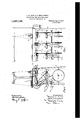
flfig. is a vertical sectionon an enlarged scalethrongh one of the knitting heads and its supporting members',
Fig, 4 is an elevation of the earn cylinf of each other, ofa numplurality Fig 5 is a detail plan of the needle retaining ring;
Fig. 6 is a development of the inner sur-` vface of the cam ring;
Figi/(is a detail section on a radial plane of' the cam-cylinder; t Fig. 8 is a'plan of a ing 'the yarnguide;
Fig. 9 is a'detail view'o vone of the webholders. y `4 A suitable casting or table A is supported by end-frames B at a convenient height, to provide a frame or housing `for the working parts. i
At the rear of the frame or housing is mounted a inain shaft 1 carrying -fast and looee drive pulleys '2 and 3 and upon which are slidably mounted a series of driving wheels 4, each having clutch lugs 5, which are capable of being thrown into and out of engagement with one of the clutch members 6 ,fast on shaft 1. Each of 'the drivingknit-ting headA showi through the agency of which rotary` motion is'mparted tothe cam ring of the knitting head; f The gearing heretofore employed in drivingv the head of a knitting machine is by this means avoided. i
Theknitting head, which is of very simplefand durable construction, consists o f the `needlecylinder 8, which also acts as a file for the reception ofthe cam ring 9, which has integrallyformed with it the eigtension 10 ca rrying.t-hel gro0ved wheel 11 Spinwheels 4 .cari'ie a quarter twist belt 7,
for the belt'7; The ioyver portion of the cylinder reduced 13 either right or left and ie threaded at "handed, depending upon the ydirection of thev rotary motion of theca'rn ring, to take a hand-aint 14S having an oil receiving channehl) in ite upper face.
The ,table- A is receseed as shown at 16 in Zand 3. is provided at the bottoni of eacl'i'iecess, having a central bose 18 ina bore"in which the needle cylinder is seated, and against the upper machined face of which shoulder of the cylindeigis tightly drawn by the nutli. Y
The cani ring is pri-:muted from riem by luge 19, 19 which are secure i for a form a shoulder 12 An integral crogsebar 17- iop construction, eXceptwin this-instance it is' justment as by screws-20, to the part l0 of the cam ring. These lugs have inturned feet which pass through openings 21 in the cam ring, and engage with an annular slot 22 formed in the needle cylinder as shown in Fig. 2.
Within the cam cylinder 9 an advancing or clearing cam 23 is seated. upon the shoulder 24 formed in said cam cylinder. The form, of this cani, shown in Figs. 6 and 7, is such as to adapt it to be made from steel tubing from which the cam maybe cut by a milling operation, then hardened, grou-nd and polished on its working face, and fitted within the recess provided for it. to the construction reliancemay be had on friction only to hold it in place. The complete circular form of the cam rin-g makes it capable of being made from tubing of a standard. size requiring no special fitting.
The stitch or draw cam 25 is of similar desirable to provide an opening for the removal upwardly of broken needles, and
the annulus or tube section' from which the cam ismade is out through longitudinally 7 at 261er this purpose.
Extremexnicety of adjustmentv s desir-.
able in machines of this class, by which it is intended to produce ata-high rate bries of small diameter' and fine gage: We provide for this by the particular adjustment for the cam shown in Figs. 3, 4, 6 and 7.
A vertical slot 27 is-milled in the Wall of the cam cylinder in which a pin or screw l2.8 fast in the cam 25 has vertical freedom of movement without play in a horizontal sense. At a lower point in said'stitchcaln 25 a headed and shouldered screw29, also movable freely in the slot 27, carries the upper end of link 30, the lower end of which surrounds the eccentric member 3l of .a stud 32 fitting in a bore 33 in the wall of the cam cylinder.' The eccentric member 3l is slotted to be adjusted by a screw driver. vBy loosenling the screw 29 a very'delicate adjustment of the stitch vcam in avertical sense may be made and the adjusting members may beclamped without altering the 'adj ustlnent by tightening saidscrew 2S) against the link 3() and the wall of the caln'cylinder, which may beflattened at this point, as at 34, tol
lgive a better holding surface.
The needles of this machine are, rela-` Owing "upon Working down opposite the annulus 51 tivelyv free, typically Working Without sufficient friction in their grooves to support them against gravity. In order to retain them in their grooves, we provide a circumferential groove 40 in the needlecylinder above the top of the cam cylinder, the bottom of which is substantially of the same diameter as the outer face of the shanks ot' the circle of needles 50. ln said groove, resting upon the shoulder' formed by the walls of the deeper needlegrooves, beneath and held down by the flange 42, which is penetrated by the needle grooves, we provide a retaining ring 41 which is split diametrically and hinged at 45. Said ring is provided withl a spring latch 43 having a 'nger grip 44, to enable it to be released to open the ring upon its diameter when it is necessary to remove or insert a needle. p The needle-cylinder 8v is grooved for the needles only on its upper half, leaving the portion 464an unbroken cylinder, except for the bearing groove 22,.
Beneath the vshoulder 24 upon which the advancing cam -rests we provide the cam cylinder with an annular groove 51, and through the walll of said cylinder communieating with said groove we provideat least one opening 52. P'l`he bottoms of the needle grooves which are milled in the needle-cylinder, slope outwardly in thelregion of the annular opening 51, so that an obstruction such as a broken needle 'or a mass vof lint accumulating in the needle grooves will be thrown out into said annulus and ultimately out through 'the opening 52, owing tio the air'blast set up by the rotation ofthe cylinder 9, within which the Walls of the needle grooves behave as stationary vanes. When the cylinder 9 is rotated at the-speedsA adopted this structure has a marked effect as a fan. T o this end to increase the effectof theair blast to clear the annulus 51, we
may slope the `opening 52 so as to Amake it 11`0 tangential to the annular 'space 51 and point- .ing in the direction of rotation, as shown in Fig.'4. The cam cylinder is further provided with a-liange 54 of suflicient size to cover the 115 opening 1G in the machine table A. This flange serves as 'a hand 'Wheel to manually move the cam v,cylinder for adjustment, and may be utilized to\counterbalance any eccentrically disposed weights found to be dis- Vtributed about the cameylinder, as by milling out portions as at in Fig. 3 lto restore balance.
We find 1n' practice, however, that the long tubular needle cylinder 8 is sufficiently vre-'12`5fv silient to permit high speeds ot' the elements rotating upon it even' when they are not in perfect balance, the cylinder" 8 deforining under them-centric strain and taking a central position with respect to the nutating 130 lift the pulley l0 suflieiently from bo especiall)y at the portion lo ol the bore in.
to set the lues 1f) to to permit a .small degree of rocking motion of th cani o rl i nder.
In pre.
the earn cylinder l0, and
sting machines of small diameter, a lthough. so tar as we are aware there has been no attempt to drive them at the :needs n'hieh` we find in yn'attiee our maoliine rapable ot' attaining, great diiliculty has been exl'ifiariented in preventing; the knit web from rising upon the upward .movefment of the needles to clear their latches.
Reliance has been had upon weighted take- VIn the' ease of a presso due to the `breaking;` of the yarn it is very difficult, on aooount of the small. diameter', to run a piece of fabric upon the .needles to start the machine. XVe avoid these difficulties by the provieion of stationary ivebdiolders 56 havingain nlgnvard grooved bevel 5T and a notch tlidefining an annular groove, tl1e external Vdiameter of Which is Close to the internal di ter of the backs of the needles. 11i-this ame poe `ion,`the noses 59 of the Web-holders serve upon the down draft of the y,needles to draw oil or sink suil'ieient yarn bet/Ween the needles whieh arestniplied by the yarn guide 60 attaelied to the earn cylinder) to form the ,stitches The use of the Structure mentioned 'permits the old or last formed eoure to bemore promptl)y knocked over the heads of the needles upon the passage of the tops of the `needles below the knockingover line determined by the bottom ot' the noteli 58 than would otherwise be the ease.
` This "ect due to the fact that the new loop drawn tl'irough the old loop at the verge or top of the needle cylinder from Yarn which has already been meaeu red oli' I the noses of `the iveb-holdt.
rmratirely l leteljv or partially, by
A The penetrating' i'rnwen'ient ol the needle hook with to the oldloop takes platre tl'iereitore vlle hook is eharged with eorn yarn and the strain muon tl' old loop, when it i5 penetrated by the new loop, is to that; extent leseened, lilir this "in the down (lr-"fatt of the needles when i elders` of the torni shown are provided teraleney than under other eir- 'to maintain the last course knit i ita'fnll liameter. The eilelift of nn to clear the laet course knit aineter defined by the so `that the next ad- .t' the needles takes place jpneriously knit etuifrse.
and sunk, either leom 'ioiiigi'noren'ient" outside. ola' the .f which the it 'contributing advantage of this structure lies in the partial independence ot the length oi the stitehes 'from the downwm'd stroke of the needles.. The noses 3.) ot' the sinkers having; drawn nearlir enough yarn for the stitch, the accidental failure to adjust the earn 2:5 to take the needles an additional distance to complete a stitch ot' the length desired does not prt-vent knitting, but merely results in a fahr-ie of the maximum stillness for which the dinn-ensions of `the noses were adjusted.
vFor most of the uses of the fabric, as for bindings, pipings, Casings, ete., it is liattened `lex'lgthnise and creased in this position, before it is sewed or fastened in place. .We have found that it isfimportant to gire the fabric its permanent form after it knit and before extensive folds or creases are impressed in it at the wrongr ioint, and to this end We ha Ve provided a take-np mechanism of ordinary construction shown as comprising the rolls T0, the worm and, worin wlieel 71. and T2 respectively, ley 73 mounted upon the swinging arm T4. As shown in Figs. l and 2 a )arate meehanism of this Character is provided for each head on the frame. A longitudinal. strut 80 on said trarne Carries, for adjustment by the screws 82, a series of arms 81, on which the frames Hof the take-up devices are pivoted at T5. The usual counterbalanee 76 provided for the take-11 i which is operated by tightening and Slaokening the belts 77 operated by the grooved pulleys 78, each on a sleeve eonnexzted to a clutch pulley 4.
The eieet of the take-up rolls 70, whicharey counter-balanced as to maintain a very li glit draft upon the forming tubes lof fabric, is to mash or {lattenthe tubes longitudinally, the line of fold coming upon tei-tain needle Walesdiametrically opposite each other.
In some eases when using hard, springy yarns, such as silk and artificial sillnl of fabric is often eonnmsed, it desirable' to retain the folded condition of the web until it is used, and `we therefore provide the reels 9U upon which the fabric is Wound under tension after passing the take-up. The reels 9 f are mounted on one sqnared end ofshor shafts 91 carried by arms 83 pivoted on the strut 80. Spring latches take against the end v of the srplared bore inthe hub portion ofthe reels to remm'al'ily lateh themv in place. W'hen full a reel may beremoved and taken, without nnwinding ita contents, to a sewing maehine or the like eni'ploying it in the Inanufacture of garments? Fast on the other end of the shaft 91 there is a grooved pulley 93 operation of the reels issimilar to that of 96 for the reels 90. The
the take-ups, the friction belt 94 slipping' upon one or the other of these pulleys as the 'tension on the winding fabric lifts the arms 83.
It will be noticed that the take-up elements of the knitting heads as -Well as the drive wheel 4 ai'e clutched and unclutchedA from the drive shaft 1 by the same clutchI mechanism 5 and 6. A shipper lever 100 pivoted at 105 on', the underside of the table A and having at its other end a pin taking in the groove 104 of theY sleeve carrying the wheels 4, 78 and 95 under the tension spring .106 tends to maintain said clutch members in their open position. A seiies of latches A101 on the front of the table A having lugs* upon the cord 107 and release the clutch,
' stopping the movement of that knittinghead, its take-up and wind-ing mechanism, without affecting the operation of the remaining heads.
The yarn supply is from cops, cones, or bobbins 109 conveniently resting upon pins on the rear of the table A from which the yarn extends upwardly through bores in the overhead guides 110, which are slipported by T-standards at the ends of the machine frame.
Ve find it unnecessary to provide any,
stop-motion actuated upon the breakage` of the yarn or the jamming of a. needle since in the one case the release of the fabric stops the head and in the other case the small niass of the rotating parts permits the driving belt to slip without damage to the head.
lt is important to prevent the splashing of oil from one head on the fabric from the neighboring heads. In addition to the channel 15, to collect waste oil, webprovide shoulders 112 on the cross-bar 17, to take. drops of oil from the lower face of the pulley 11,.befoi'e they are `freed and thrown olf centrifugally. The oil `collected by the shoulders 112 flows down the surfaces of the cross-bar 17 and into the channel 15,
Having described our invention what we claim and desire to secure by Letters Patent is l. In a knitting machine, a rotary cani element, and means to support it for rota"- tion about an axis variable in response to its mass and speed.
2. -In a knittingr machine a fixed needle cylinder of a height greatly in excess of its diameter, grooves in said cylinder, needles in said grooves, annular bearing surfaces formed on said cylinder, a cam cylinder 'loosely surrounding said needle cylinder having needle cams thereon, and adjustable .lugs entering between said bearing surfaces,
and a flexible friction belt for rotating said cam cylinder at high speeds.
3. In a knitting machine, a vertical needle cylinder of a height greatly in excess of its diameter, whereby said cylinder is laterally resilient, a fixed mounting for the lower end` of the said cylinder. and a rotary cani-cylinder freely surrounding said needle cylinder and having a bearingthereon above its fixed portion, whereby said cam-cylinder is capable of rotation at high speeds about-an axis of rotation out of coincidence with` its axis of figure.
4. In a knitting machine, alongitudinally grooved needle-cylinder and independent needles therein, a cani-cylinder supported 'by the needle cylinder and means for adjusting the longitudinal position of the camsii cylinder, fixed web-holders having noses within `the external diameter of the needles, I
and notches beneath said noses, an advancing cani, a stitch am and means for adpisting thfe .stitch-cani longitudinally of the cam- 5. In a knitting machine, a carrier `and independently movable needles therein, Ya cani carrier and cams foracting on the needles, comprising a cam having a guide pin working in a. slot in said cam carrier, a stud in said cam-carrier having an eccentric part,` a link surrounding at one end said eccell-y tric part, and a screw in said eani having a bearing in the other end of said link.
(i. In a knitting machine, a machine table presenting a circular openinff, a cross-bar dianietrical of said opening and beneath it, a
needle-cylinder mounted centrally upon thecross-bai', and a cani cylinder mounted for rotation on the needle cylinder having al drive-'pulley thereon beneath the, said table.
7. In a knitting machine. a machine table presenting a circular opening, a cross-bar diainetrical of'said opening and beneath it, a ncedleazylindcr mounted centrally upon the cross-bar, and a cain-cylindi.\r mounted for rotation on the n\eed,lecylinder having a drive-pulley thereon beneath the plane of said table, and a circular `flange above said table covering said circular opening.
h'. In a multiple head'knitting machine, a frame for supporting the parts, relatively plane of ixcd needle cylinders, rotary cani cylinders i cach having a bearing on one of said needle cylinders, a drive pulley on the lower part of each cam cyliiuler, andan oil wiping shoulder on a part of the frame near the periphery of each pulley.
0. In a knitting inachine, a frame for .supporting the parts,` a relatively fixed needlecylinder having a shoulder and threaded los manioc lower end in a bore in the' frime, urotay' cam-cylinder having a. bearing on said 110e-r (lle-Cylinder,
a' drive mechanism for said egim-cylinder, and a nut to hold the needlefl cylinder seated having :in annular oil-pocket viny its upper face.
10. In a knitting inachine, a needlevcylinf der hving grooves termmating in slopes to un unbroken"surface, in combination with s, l0 cam cylinder surrounding the needle cylinder. said cam-cylinder having, oppositel the bottoms of the grooves, an annular recess to r'eceive broken pn rts 0r lint from the grooves, I and an openll'xg from the outside of said cylinqer communiating'lwith said annular w 15 cesa".
In ybespmony" whereof we have sixed our. names inA they presence of the su cribing Witnesees.
ROBERT W. SCCTT. l i HARRY SWINGLEHURST. Witnesses for Scott:
ALBERT Et PAGE, WALTER LARKIN.
VWitnesses for Swinglehurst: s
CHARLES H. BREAITHWMTE,
J. H. BOND.
Priority Applications (1)
| Application Number | Priority Date | Filing Date | Title |
|---|---|---|---|
| US71452512A US1237106A (en) | 1912-08-12 | 1912-08-12 | Knitting-machine for narrow webs. |
Applications Claiming Priority (1)
| Application Number | Priority Date | Filing Date | Title |
|---|---|---|---|
| US71452512A US1237106A (en) | 1912-08-12 | 1912-08-12 | Knitting-machine for narrow webs. |
Publications (1)
| Publication Number | Publication Date |
|---|---|
| US1237106A true US1237106A (en) | 1917-08-14 |
Family
ID=3304925
Family Applications (1)
| Application Number | Title | Priority Date | Filing Date |
|---|---|---|---|
| US71452512A Expired - Lifetime US1237106A (en) | 1912-08-12 | 1912-08-12 | Knitting-machine for narrow webs. |
Country Status (1)
| Country | Link |
|---|---|
| US (1) | US1237106A (en) |
Cited By (5)
| Publication number | Priority date | Publication date | Assignee | Title |
|---|---|---|---|---|
| US3368372A (en) * | 1965-01-04 | 1968-02-13 | Madison Throwing Company Inc | Fabric take-up for circular knitting machine |
| US4231234A (en) * | 1975-10-03 | 1980-11-04 | Sulzer Morat Gmbh | Assembly plate for assembling cam parts of a knitting machine |
| US4233825A (en) * | 1978-05-05 | 1980-11-18 | Glitsch, Inc. | Knitting machine |
| US4977759A (en) * | 1988-04-18 | 1990-12-18 | New England Overseas Corporation, Inc. | Circular warp knitting machine |
| US20240338922A1 (en) * | 2021-12-22 | 2024-10-10 | Huawei Technologies Co., Ltd. | Fusion positioning method based on multi-type map and electronic device |
-
1912
- 1912-08-12 US US71452512A patent/US1237106A/en not_active Expired - Lifetime
Cited By (5)
| Publication number | Priority date | Publication date | Assignee | Title |
|---|---|---|---|---|
| US3368372A (en) * | 1965-01-04 | 1968-02-13 | Madison Throwing Company Inc | Fabric take-up for circular knitting machine |
| US4231234A (en) * | 1975-10-03 | 1980-11-04 | Sulzer Morat Gmbh | Assembly plate for assembling cam parts of a knitting machine |
| US4233825A (en) * | 1978-05-05 | 1980-11-18 | Glitsch, Inc. | Knitting machine |
| US4977759A (en) * | 1988-04-18 | 1990-12-18 | New England Overseas Corporation, Inc. | Circular warp knitting machine |
| US20240338922A1 (en) * | 2021-12-22 | 2024-10-10 | Huawei Technologies Co., Ltd. | Fusion positioning method based on multi-type map and electronic device |
Similar Documents
| Publication | Publication Date | Title |
|---|---|---|
| US2158547A (en) | Yarn furnishing device | |
| US1237106A (en) | Knitting-machine for narrow webs. | |
| US3421344A (en) | High-speed knitting machine | |
| US2387260A (en) | Spindle | |
| US810578A (en) | Knitting-machine. | |
| US2403864A (en) | Sinker guide for knitting machines | |
| TW201638415A (en) | Circular knitting machine | |
| US2098050A (en) | Knitting machine | |
| GB473365A (en) | Improvements in or relating to the manufacture of circular knitted articles with pouches | |
| US2141042A (en) | Knitting machine and method of operating same | |
| US2082642A (en) | Sinker or web holder control | |
| US672182A (en) | Knitting-machine. | |
| US1396120A (en) | Oiling device for fiber silk and the like | |
| US694515A (en) | Yarn-changing mechanism for circular-knitting machines. | |
| US2251222A (en) | Fabric take-up | |
| US2644325A (en) | Circular knitting machine | |
| US554475A (en) | Chusetts | |
| KR101198190B1 (en) | Medium or large diameter single cylinder circular knitting machine with radially compact sinker ring | |
| US3000199A (en) | Knitting machine and method | |
| US2431134A (en) | Adjustable swing bracket | |
| US1867635A (en) | Yarn furnisher | |
| US625234A (en) | Knitting-machine | |
| US1201511A (en) | Spring-needle circular-knitting machine. | |
| US1070191A (en) | Rib-knitting machine. | |
| US2971360A (en) | Knitting machine |