US1237017A - Drill-head for drilling-machines. - Google Patents
Drill-head for drilling-machines. Download PDFInfo
- Publication number
- US1237017A US1237017A US8113216A US8113216A US1237017A US 1237017 A US1237017 A US 1237017A US 8113216 A US8113216 A US 8113216A US 8113216 A US8113216 A US 8113216A US 1237017 A US1237017 A US 1237017A
- Authority
- US
- United States
- Prior art keywords
- drill
- head
- socket
- spindle
- casings
- Prior art date
- Legal status (The legal status is an assumption and is not a legal conclusion. Google has not performed a legal analysis and makes no representation as to the accuracy of the status listed.)
- Expired - Lifetime
Links
- 238000005553 drilling Methods 0.000 description 30
- 230000008878 coupling Effects 0.000 description 17
- 238000010168 coupling process Methods 0.000 description 17
- 238000005859 coupling reaction Methods 0.000 description 17
- 150000001875 compounds Chemical class 0.000 description 10
- 238000010276 construction Methods 0.000 description 6
- 230000004048 modification Effects 0.000 description 2
- 238000012986 modification Methods 0.000 description 2
- 230000008901 benefit Effects 0.000 description 1
- 210000005069 ears Anatomy 0.000 description 1
- 238000004519 manufacturing process Methods 0.000 description 1
- 230000007246 mechanism Effects 0.000 description 1
- 230000002093 peripheral effect Effects 0.000 description 1
- 230000000717 retained effect Effects 0.000 description 1
Images


Classifications
-
- B—PERFORMING OPERATIONS; TRANSPORTING
- B23—MACHINE TOOLS; METAL-WORKING NOT OTHERWISE PROVIDED FOR
- B23B—TURNING; BORING
- B23B39/00—General-purpose boring or drilling machines or devices; Sets of boring and/or drilling machines
- B23B39/16—Drilling machines with a plurality of working-spindles; Drilling automatons
- B23B39/161—Drilling machines with a plurality of working-spindles; Drilling automatons with parallel work spindles
- B23B39/162—Drilling machines with a plurality of working-spindles; Drilling automatons with parallel work spindles having gear transmissions
-
- Y—GENERAL TAGGING OF NEW TECHNOLOGICAL DEVELOPMENTS; GENERAL TAGGING OF CROSS-SECTIONAL TECHNOLOGIES SPANNING OVER SEVERAL SECTIONS OF THE IPC; TECHNICAL SUBJECTS COVERED BY FORMER USPC CROSS-REFERENCE ART COLLECTIONS [XRACs] AND DIGESTS
- Y10—TECHNICAL SUBJECTS COVERED BY FORMER USPC
- Y10T—TECHNICAL SUBJECTS COVERED BY FORMER US CLASSIFICATION
- Y10T74/00—Machine element or mechanism
- Y10T74/19—Gearing
- Y10T74/19023—Plural power paths to and/or from gearing
Definitions
- This invention relates to a drill head for drilling machines, and the primary object of my invention is to provide a multiple drill head which may be bodily adjusted in lateral and vertical planes relative to a piece of-work, whereby drilling operations may be expeditiously performed in an accurate and eflicient manner by machinists or other artisans.
- Another object of my invention is to pro vide a multiple drill head with individual end drills that may be individually adjusted v in lateral or vertical planes or moved in synchronism in a lateral plane, thus permitting of drilling operations being carried on at convenient-locations relative to a piece of work in a drilling machine, or to the operator or attendant of the machine.
- a further object of my invention is to provide a multiple drill head that is applicable to various types of drilling machines, andwherein the parts are constructed with a view of reducing the cost of manufacture and at the same time retain the features by which safety, durability and ease of assembling are secured, and with such ends in view, my invention resides in.
- end drill has an individual vertical adjustment
- Fig. 6 is a front elevation of a portion of a drill head, partly broken away and partly in section, illustrating a further modification of my invention
- Fig. 7 is a bottom plan of the same partly broken away and partly in section;
- Fig. 8 is a diagrammatic view illustrating the adaptability of the drill head to various drilling machine spindles
- Fig. 9 is an elevation of the stationary drill head, partly broken away and partly in section, illustrating its connection with an attaching member, and
- Fig. 10 is'a longitudinal section of a telescopic rack sleeve.
- 1 denotes a portion of the driven spindle of an ordinary drilling machine, said spindle having the lower end thereof provided with a head 2 and a socket to receive the tapering shank 3 of a coupling member 4.
- the rack sleeve 5 has a longitudinal rack 8 adapted to be raised and lowered by the for, whereby my improved drill head can be attached to the rack sleeve of various types of drilling machines. 7
- 1() denotes an 'attachin member of the drill head, and said attac ing member has the upper end thereof bifurcated and formed with opposing ears 11 for bolts 12 adapted to clamp the attaching member on the rack sleeve 5.
- the lower end of the attaching member terminates in a circular head 13 provided with a concentric bearing 14 for a sleeve 14*, said sleeve receiving a bearing portion 13 of the coupling member 4.
- ' 15 denotes a slide band shiftable circumferentially of the head 13 of the attaching member and said slide band has diametrically opposed bosses 16 provided with screw bolts 17 and retaining washers 18.
- the retaining washers 18 extend on to the top of the head 13, as best shown in Figs. 1 and 2, and thereby supports the slide band 15 relative to said head, yet permit of circumferential adjustment.
- the top plate 20 has diametrically opposed openings 22, two in number in contradistinction to the four bosses 16, and the two openings 22 are in proximity to two of the bosses 16, as shown in Fig. 1.
- the openings 22 receive the hubs .23 of stepped or compound gears within the ends of the gear housing.
- the compound gears have large gears 24 adjacent the hubs 23 and small gears 25 adjacent hubs 26. Extending through the hubs 23 and 26 and longitudinally of the compound gears are pivot pins 27 having heads 28 countersunk in the top of the plate 20.
- the compound gears freely rotate upon the pivot pins 27 and the large gears 24 mesh with a central gear 29 having a hub portion 30 within the sleeve 14 of the bearing 14 of the head 13,
- the central gear 29 is mounted upon the stem 31 of the coupling member 4 against the bearing p0rtion'13 thereof for rotation therewith and the lower end' of the stem'31 has astransverse groove 32, the purpose of which will hereinafter appear.
- 33 denotes circular heads forming the bottom of the oblong gear housing 19 and these heads are connected by a web portion 34,-as best shown in Fig. 3. The web portion.
- the outer ends of said casings have bosses 39 engaging the peripheral edges of the heads 33 and said bosses are provided with screw bolts 40 and retaining washers 41, said washers extending on to the heads 33 to cooperate with the pivot pins in supporting socket casings relative to the gear housings 19.
- bearing portions 42 denotes casings 37 and these bearing portions extend into the circular openings 36 of the heads 33 to assist in properly centering the inner ends of the socket casings relative to said heads.
- the bearing portions 42 are slotted, as at 43 to provide clearance for the small gears 25 and to permit of easy access being had to the interior of the socket casings.
- socket members 45 adapted to receive end drill shanks 46.
- Thrust bearings 47 are interposed between the lower ends of the socket members 45 and the lower ends of the bearings 44.
- the upper ends of the socket members 45 extend into the casings 37 and are provided with gears 48. meshing with the small gears 25, whereby the end drill shanks 46 can be driven from the drilling machine spindle 1.
- a socket member 52 provided with a tang 53 extending into the groove 32 of the stem 31, whereby the central socket member 52 can be rotated in synchronism with the drilling machine spindle 1.
- the central socket member 52 is retained in the bearing 51 by a collar 54 mounted upon the upper end thereof within the opening 35 of the web 34, and the lower end of the socket member has a thrust bearing 55 and is adapted to receive a central drill shank 56.
- the drill head may be properly adjusted in a vertical plane to properly position the end and central drills relative to a piece of work.
- the gear housing 19 may be properly adjusted in a horizontal plane relative to the head 13 by simply loosening the screw bolts 17 and turning the oblong gear housing 19 to a desired position, at which time the screw bolts 17 are tightened to hold the gear housing 6 relative the attaching member 10.
- the socket casings 37 may be individually adjusted in a horizontal plane relative to the heads 33, and consequently the end drills may be swung in a horizontal plane and positioned at any desired angle relative to the central drill. Throughout both adjustments the train of gears between the drilling machine spindle and the end drills is maintained intact, and the central drill is driven direct from the coupling member of the drilling machine spindle, irrespective of the position of the end drills.
- the drills be placed in'a common vertical plane or in alinement to avoid stresses and strains on the train of gears during drilling operations. It is obvious that with all three drills in a row that one end drill balances the other, and stresses and strains are balanced on opposite sides of the central drilling mechanism.
- a drill head may be bodily adjusted in a vertical plane, and to permit of drills being individbearing 62, and there is sutlicient clearance within the socket casing 57 for vertical adjustment of a gear 63 mounted upon the upper end of the socket member. 60.
- the end drills can be individually adjusted and to allow the drills to be moved in synchronism there is shown a horizontally .disposed casings 68 similar to the casings 37. From this construction it is apparent that when one of the socket casings is adjusted that the other socket casing is moved in an opposite direction to that of the shifted casing, con-- sequently the drills are maintained in a common plane intersecting the vertical axis of the drill heads.
- Fig. 8 there is illustrated the adaptability of the drill head to various types of drilling machines having spindles 70 of various lengths requiring attaching members of various lengths, and coupling members with tapers corresponding to that of the drilling machine spindle.
- a very short drill spindle requires a short attaching member 71 and a short coupling member 72 with the taper of the coupling membercorresponding to the taper of the short drill spindle.
- a long drill spindle requires a long attaching member 73 and a long coupling member 74, with a taper corresponding to that of the'drill spindle.
- my improved drill head is applicable to any spindle by sim ly changing the 7 size of the attaching mem er and the coupling member. It is therefore apparent that if a machine shop is equipped with various types of drilling machine, that my improved drill head can be used in connection with any of these machines by simply having on hand attaching member and coupling members of various sizes. This obviates the necessity of having drill heads especially designed for a special make of drilling machine.
- a drill head designed to be permanently secured to anattaching member, thereby dispensing with any lateralhorizontal adjustment, yet retaining those features by which a multiplicity of drills may be operated in synchronism.
- FIG. 10 A very important feature of my invention is illustrated in Fig. 10, showing telescopic attaching members 75 and 76, the former fitting within the latter thus permitting of the attaching members being adjusted rela -iao dle, thusobviating the necessity of attaching members of various lengths, as shown in Fig. 8.
- a drill head comprising a member, adapted for vertical adjustment relative to a drilling spindle, a housing carried by said member and adapted for adjustment by rotation in a horizontal plane about the axis of said member, means engaging on the edges of said member adapted for holding said housing in an adjusted position, a center drill socket member supported from said housing, end drill socket members supported from said housings and adapted for adjustment relative thereto, and a train of gears including compound gears completely inclosed by said housing ada ted to rotate said center and end drill soc et members.
- a drill head comprising a member adapted for vertical adjustment relative to a drilling spindle, a housin carried by said member and adapted for adjustment in a horizontal plane, casings carried by said housing, a center drill socket member supported from said housing, end drill socket members supported from said casings and adapted for independent adjustment in a horizontal plane relative to said housing, and a train of gears including compound gears completely inclosed by said housing and said casings adapted to rotate said center and end drill socket members.
- a drill head comprising a member adapted for vertical adjustment relative to a drilling spindle, a housing carried by said member, a center drill socket member supported by said housing, end drill socket members supported from said housing and adapted for independent adjustment in a horizontal plane relative to said housing, means ofiset relative to the axes of said drill socket members adapted to engage on the edges of said housing to hold said drill socket members in adjusted positions and till means axially of said housing adapted to rotate said center and end drill socket members in synchronism-and in the same direction.
- a drill head comprising a horizontally adjustable gear housing, individual, horizontally adjustable and rotatable socket members supported by said gear housing, means ofi'set relative to the axes of said drill socket members adapted to engage on the edges of said housing to hold said drill socket members in adjusted positions and means actuated centrally of said gear housing adapted to rotate said socket members.
- a drilling machine having a spindle, of a member adapted for attachment to said machine, said member comprising a head, a horizontally adjustable gear housing carried by said head, means oiset relative to the axis of said head adapted to engage on said head and hold said head stationary, depending pivot pins carried by said housing, a casing on each pin, means odset relative to the axis of each casing adapted to hold the casings stationary, a drill socket member supported from each casing, and compound gears in said hous ing extendin into said casings adapted for rotating sai drill socket members in synchronism and in the same direction.
Landscapes
- Engineering & Computer Science (AREA)
- Mechanical Engineering (AREA)
- Drilling And Boring (AREA)
Description
J. F. BUHR. DRILL HEAD ron DRILLING MACHINES.
APPLICATIONTILED FEB. 2911 916.
Patented Aug. '14, 1917.
wmob
J. F. BUHR.
DRILL HEAD FOR DRILLING MACHINES.
1,237017. APPLICATION men ms. 29. me. Q PatentedAugo 14"].917'
' 4 SHEETS-SHEET a 0 4 0 Q 3 Mm 7 H To J WW M au mi j l IHH M 7 l| 6 n9 6 M W 3 0 5 4 II. 6
Patented Aug. 14, 1-917. I
4 SHEETS-SHEET 4.
JOSEPH F. B'U'HE, 0F DETROIT, MICHIGAN.
DRILL-HEAD FOR DRILLING-MACHINES.
Specification of Letters Patent.
Application filed February 29, 1916. Serial No. 81,132.
To all whom it may concern:
Be itknown that I, Josnrrr F. BUHR, a citizen of the United States of America, residing at Detroit, in the county of Wayne and State of Michigan, have invented certain new and useful Improvements in Drill- Heads for Drilling-Machines, of which the following is a specification, reference being had therein ,to the accompanying drawings.
This invention relates to a drill head for drilling machines, and the primary object of my invention is to provide a multiple drill head which may be bodily adjusted in lateral and vertical planes relative to a piece of-work, whereby drilling operations may be expeditiously performed in an accurate and eflicient manner by machinists or other artisans.
Another object of my invention is to pro vide a multiple drill head with individual end drills that may be individually adjusted v in lateral or vertical planes or moved in synchronism in a lateral plane, thus permitting of drilling operations being carried on at convenient-locations relative to a piece of work in a drilling machine, or to the operator or attendant of the machine.
A further object of my invention is to provide a multiple drill head that is applicable to various types of drilling machines, andwherein the parts are constructed with a view of reducing the cost of manufacture and at the same time retain the features by which safety, durability and ease of assembling are secured, and with such ends in view, my invention resides in.
the novel construction, combination and arrangement of parts to be hereinafter specifically described and then claimed.
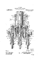
Reference will now be had to the drawings, wherein-- Figure 1 is a vertical sectional view of a I drill head inaccordance with my invention;
end drill has an individual vertical adjustment;
Fig. 6 is a front elevation of a portion of a drill head, partly broken away and partly in section, illustrating a further modification of my invention;
Fig. 7 is a bottom plan of the same partly broken away and partly in section;
Fig. 8 is a diagrammatic view illustrating the adaptability of the drill head to various drilling machine spindles;
Fig. 9 is an elevation of the stationary drill head, partly broken away and partly in section, illustrating its connection with an attaching member, and
Fig. 10, is'a longitudinal section of a telescopic rack sleeve.
In describing my invention by aid of the views above referred to, I desire to point out that the same are intended as merely ,illustrative of an example whereby my invention may be applied in practice, and I do not care to limit my invention to the precise construction and arrangement of parts shown except as required by the scope of the claims. The following description is therefore to be broadly construed as includ- 1ng substitute constructions and arrangements of parts which are the obvious equivalent of those to be hereinafter referred to.
In the drawings, 1 denotes a portion of the driven spindle of an ordinary drilling machine, said spindle having the lower end thereof provided with a head 2 and a socket to receive the tapering shank 3 of a coupling member 4.
5 denotes a rack sleeve loose upon the spindle l and provided with an oblong opening 6' adapted to register with a similar opening in the spindle 1 whereby easy access can be had to the tang 7 of the coupling member shank 3 for forcing the coupling member shank 3 out of the spindle 1..
The rack sleeve 5 has a longitudinal rack 8 adapted to be raised and lowered by the for, whereby my improved drill head can be attached to the rack sleeve of various types of drilling machines. 7
1() denotes an 'attachin member of the drill head, and said attac ing member has the upper end thereof bifurcated and formed with opposing ears 11 for bolts 12 adapted to clamp the attaching member on the rack sleeve 5. The lower end of the attaching member terminates in a circular head 13 provided with a concentric bearing 14 for a sleeve 14*, said sleeve receiving a bearing portion 13 of the coupling member 4.
' 15 denotes a slide band shiftable circumferentially of the head 13 of the attaching member and said slide band has diametrically opposed bosses 16 provided with screw bolts 17 and retaining washers 18. The retaining washers 18 extend on to the top of the head 13, as best shown in Figs. 1 and 2, and thereby supports the slide band 15 relative to said head, yet permit of circumferential adjustment.
19 denotes an oblong gear housing depending from the slide band 15, said housing having the top plate 20 thereof against the bottom side of the head. 13 and formed with an opening 21 to receive the bearing 14 of said head. The top plate 20 has diametrically opposed openings 22, two in number in contradistinction to the four bosses 16, and the two openings 22 are in proximity to two of the bosses 16, as shown in Fig. 1. The openings 22 receive the hubs .23 of stepped or compound gears within the ends of the gear housing. The compound gears have large gears 24 adjacent the hubs 23 and small gears 25 adjacent hubs 26. Extending through the hubs 23 and 26 and longitudinally of the compound gears are pivot pins 27 having heads 28 countersunk in the top of the plate 20. The compound gears freely rotate upon the pivot pins 27 and the large gears 24 mesh with a central gear 29 having a hub portion 30 within the sleeve 14 of the bearing 14 of the head 13, The central gear 29 is mounted upon the stem 31 of the coupling member 4 against the bearing p0rtion'13 thereof for rotation therewith and the lower end' of the stem'31 has astransverse groove 32, the purpose of which will hereinafter appear. 33 denotes circular heads forming the bottom of the oblong gear housing 19 and these heads are connected by a web portion 34,-as best shown in Fig. 3. The web portion. 34 has an opening 35 to receive the lower end of the central gear hub 30 and the circular heads 33 have circular openings 36 through which protrude the small gears 25 and the pivot pins 26. Tt-is to be noted that the small gears 25 and the pivot pins 27 are concentric of the circular heads 33..
37 denotes oblong individually adjustable socket casings held against the heads 33 by nearer? the pivot pins 27. The inner-ends of the casin s 37 have openings to receive the hubs 26 ot the lower ends of the pivot pins 27 hold the casings 37 against the bottom side of the heads 33 whereby said casings can be swung in a horizontal plane beneath said heads. To hold the casings 37 in adjusted positions, the outer ends of said casings have bosses 39 engaging the peripheral edges of the heads 33 and said bosses are provided with screw bolts 40 and retaining washers 41, said washers extending on to the heads 33 to cooperate with the pivot pins in supporting socket casings relative to the gear housings 19.
42 denotes casings 37 and these bearing portions extend into the circular openings 36 of the heads 33 to assist in properly centering the inner ends of the socket casings relative to said heads. The bearing portions 42 are slotted, as at 43 to provide clearance for the small gears 25 and to permit of easy access being had to the interior of the socket casings.
bearing portions of the socket the compound gears, and nuts 38 on 44 denotes depending bearings at the outer ends of the casings 37 and in said bearings. are socket members 45 adapted to receive end drill shanks 46. Thrust bearings 47 are interposed between the lower ends of the socket members 45 and the lower ends of the bearings 44. The upper ends of the socket members 45 extend into the casings 37 and are provided with gears 48. meshing with the small gears 25, whereby the end drill shanks 46 can be driven from the drilling machine spindle 1.
49 denotes screw bolts holding the upper end 50 of a stationary central bearing 51 in engagement with the web 34 of the heads 33. Journaled in the central bearing 51 is a socket member 52 provided with a tang 53 extending into the groove 32 of the stem 31, whereby the central socket member 52 can be rotated in synchronism with the drilling machine spindle 1. The central socket member 52 is retained in the bearing 51 by a collar 54 mounted upon the upper end thereof within the opening 35 of the web 34, and the lower end of the socket member has a thrust bearing 55 and is adapted to receive a central drill shank 56.
Before considering modifications of my invention, it is thought best to consider the operation and certain adjustments of the drill head just described, i
It is through the medium of the sleeve 5 that the drill head may be properly adjusted in a vertical plane to properly position the end and central drills relative to a piece of work. Through the medium of certain micrometer graduations or scales on the heads 13 and 33, such graduations or scales forming no part of this invention, the gear housing 19 may be properly adjusted in a horizontal plane relative to the head 13 by simply loosening the screw bolts 17 and turning the oblong gear housing 19 to a desired position, at which time the screw bolts 17 are tightened to hold the gear housing 6 relative the attaching member 10.
By loosening the screw bolts 40 the socket casings 37 may be individually adjusted in a horizontal plane relative to the heads 33, and consequently the end drills may be swung in a horizontal plane and positioned at any desired angle relative to the central drill. Throughout both adjustments the train of gears between the drilling machine spindle and the end drills is maintained intact, and the central drill is driven direct from the coupling member of the drilling machine spindle, irrespective of the position of the end drills.
As an instance of the advantage of having end drills adjustable relative to a central drill of a multiple drill head, it is a desideratum when drilling a plurality of holes in a row, in a piece of work, to have the operations carried on as near the front side of the drilling machine. as possible, and if permissible, in parallelism with the front side or edge of the drilling machine, whereby an attendant or operator of a machine can easily observe each and every hole being drilled. It is a well knownfact that it is not always possible to position a work holder or piece of work whereby a row of holes to be drilled will be in parallelism with the front side of a drilling machine, therefore, the end drills can be adjusted relative to the central drill or all three drills bodily adjusted thus allowing the attendant or operator of a drilling machine to position the drills whereby operations can be easily observed and a high degree of accuracy assured.
Furthermore, with a multiple drill head, it is desirable that the drills be placed in'a common vertical plane or in alinement to avoid stresses and strains on the train of gears during drilling operations. It is obvious that with all three drills in a row that one end drill balances the other, and stresses and strains are balanced on opposite sides of the central drilling mechanism.
In the construction just described, a drill head may be bodily adjusted in a vertical plane, and to permit of drills being individbearing 62, and there is sutlicient clearance within the socket casing 57 for vertical adjustment of a gear 63 mounted upon the upper end of the socket member. 60.
In the preferred form of construction, the end drills can be individually adjusted and to allow the drills to be moved in synchronism there is shown a horizontally .disposed casings 68 similar to the casings 37. From this construction it is apparent that when one of the socket casings is adjusted that the other socket casing is moved in an opposite direction to that of the shifted casing, con-- sequently the drills are maintained in a common plane intersecting the vertical axis of the drill heads.
In Fig. 8 there is illustrated the adaptability of the drill head to various types of drilling machines having spindles 70 of various lengths requiring attaching members of various lengths, and coupling members with tapers corresponding to that of the drilling machine spindle. For instance, a very short drill spindle requires a short attaching member 71 and a short coupling member 72 with the taper of the coupling membercorresponding to the taper of the short drill spindle. Then again, a long drill spindle requires a long attaching member 73 and a long coupling member 74, with a taper corresponding to that of the'drill spindle. Irrespective of the size or length of the drill spindle, my improved drill head is applicable to any spindle by sim ly changing the 7 size of the attaching mem er and the coupling member. It is therefore apparent that if a machine shop is equipped with various types of drilling machine, that my improved drill head can be used in connection with any of these machines by simply having on hand attaching member and coupling members of various sizes. This obviates the necessity of having drill heads especially designed for a special make of drilling machine. I
In Fig. 9 there is shown a drill head designed to be permanently secured to anattaching member, thereby dispensing with any lateralhorizontal adjustment, yet retaining those features by which a multiplicity of drills may be operated in synchronism.
A very important feature of my invention is illustrated in Fig. 10, showing telescopic attaching members 75 and 76, the former fitting within the latter thus permitting of the attaching members being adjusted rela -iao dle, thusobviating the necessity of attaching members of various lengths, as shown in Fig. 8.
Elli
What ll claim is 1. A drill head comprising a member, adapted for vertical adjustment relative to a drilling spindle, a housing carried by said member and adapted for adjustment by rotation in a horizontal plane about the axis of said member, means engaging on the edges of said member adapted for holding said housing in an adjusted position, a center drill socket member supported from said housing, end drill socket members supported from said housings and adapted for adjustment relative thereto, and a train of gears including compound gears completely inclosed by said housing ada ted to rotate said center and end drill soc et members.
2. A drill head comprising a member adapted for vertical adjustment relative to a drilling spindle, a housin carried by said member and adapted for adjustment in a horizontal plane, casings carried by said housing, a center drill socket member supported from said housing, end drill socket members supported from said casings and adapted for independent adjustment in a horizontal plane relative to said housing, and a train of gears including compound gears completely inclosed by said housing and said casings adapted to rotate said center and end drill socket members.
3. A drill head comprising a member adapted for vertical adjustment relative to a drilling spindle, a housing carried by said member, a center drill socket member supported by said housing, end drill socket members supported from said housing and adapted for independent adjustment in a horizontal plane relative to said housing, means ofiset relative to the axes of said drill socket members adapted to engage on the edges of said housing to hold said drill socket members in adjusted positions and till means axially of said housing adapted to rotate said center and end drill socket members in synchronism-and in the same direction.
4. A drill head comprising a horizontally adjustable gear housing, individual, horizontally adjustable and rotatable socket members supported by said gear housing, means ofi'set relative to the axes of said drill socket members adapted to engage on the edges of said housing to hold said drill socket members in adjusted positions and means actuated centrally of said gear housing adapted to rotate said socket members.
5. The combination With a drillin machine having a spindle, of a member a apted nearer? for attachment to said machine to be vertically adjusted relative thereto, said member comprising a head, a horizontally adjustable gear housing carried by said head, circular heads carried by said gear housing, horizontally adjustable socket casings supported from said gear housing and adapted to be fixed relative to said circular heads, drill socket members supported from said socket casing, a spindle coupling member in said gear housing, a drill socket member coupled to said spin 1e coupling member, and means in said gear housing and said socket casings for imparting movement to the first mentioned drill socket members from said spindle coupling member.
6, The combination with a drilling machine having a spindle, of a member adapted for attachment to said machine, said member comprising a head, a horizontally adjustable gear housing carried by said head, circular heads carried by said gear housing,
horizontally adjustable sockets supported by said gear housing and adapted to be fixed relative to said circular heads, drill socket members supported from said socket casings, a spindle coupling member in said gear housing, and means in said gear housing and said socket casings for imparting movement to said drill socket members, from said spindle coupling member.
7. The combination With a drilling machine having a spindle, of a non-rotatable member adapted for attachment to said machine, said member comprising a head, a horizontally adjustable gear housing carried by said head, means ofiset relative to the axis of said head adapted to engage on said head and hold said head stationary, depending pivot pins carried by said housing, a
casing on each pin, means ofiset relative to the axis of each casing adapted to hold the casings stationary, a drill socket member supported from each casing, and compound gears in said housing extending into said casings adapted for imparting movement to said drill socket members.
8. llhe combination with. a drilling machine having a spindle, of a member adapted for attachment to said machine, said member comprising a head, a horizontally adjustable gear housing carried by said head, means oiset relative to the axis of said head adapted to engage on said head and hold said head stationary, depending pivot pins carried by said housing, a casing on each pin, means odset relative to the axis of each casing adapted to hold the casings stationary, a drill socket member supported from each casing, and compound gears in said hous ing extendin into said casings adapted for rotating sai drill socket members in synchronism and in the same direction.
9. In a drilling machine, a spindle, a
member having a central bearing; a spindle extending into said casings and actuated by 10 driven connection through the bearing of the gears extending therein.
said member, a horizontally adjustable hous- In testimony whereof I aflix my signature ing attached to said member and rotatable in presence of two witnesses.
on the bearing of said member, casings carried by said housing, compound gears inp JOSEPH BUHR' closed by said housing and actuated by said Witnesses: spindle driven connection. and extending ANNA M. Donn,
into said casings, and drill socket members KARL H. BUTLER.
Priority Applications (1)
| Application Number | Priority Date | Filing Date | Title |
|---|---|---|---|
| US8113216A US1237017A (en) | 1916-02-29 | 1916-02-29 | Drill-head for drilling-machines. |
Applications Claiming Priority (1)
| Application Number | Priority Date | Filing Date | Title |
|---|---|---|---|
| US8113216A US1237017A (en) | 1916-02-29 | 1916-02-29 | Drill-head for drilling-machines. |
Publications (1)
| Publication Number | Publication Date |
|---|---|
| US1237017A true US1237017A (en) | 1917-08-14 |
Family
ID=3304836
Family Applications (1)
| Application Number | Title | Priority Date | Filing Date |
|---|---|---|---|
| US8113216A Expired - Lifetime US1237017A (en) | 1916-02-29 | 1916-02-29 | Drill-head for drilling-machines. |
Country Status (1)
| Country | Link |
|---|---|
| US (1) | US1237017A (en) |
Cited By (2)
| Publication number | Priority date | Publication date | Assignee | Title |
|---|---|---|---|---|
| US2450065A (en) * | 1943-08-04 | 1948-09-28 | United Shoe Machinery Corp | Drilling machine |
| CN107088664A (en) * | 2017-05-16 | 2017-08-25 | 常州市翰琪电机有限公司 | A kind of numerical control gang drill device |
-
1916
- 1916-02-29 US US8113216A patent/US1237017A/en not_active Expired - Lifetime
Cited By (3)
| Publication number | Priority date | Publication date | Assignee | Title |
|---|---|---|---|---|
| US2450065A (en) * | 1943-08-04 | 1948-09-28 | United Shoe Machinery Corp | Drilling machine |
| CN107088664A (en) * | 2017-05-16 | 2017-08-25 | 常州市翰琪电机有限公司 | A kind of numerical control gang drill device |
| CN107088664B (en) * | 2017-05-16 | 2019-06-14 | 常州市翰琪电机有限公司 | A kind of numerical control gang drill device |
Similar Documents
| Publication | Publication Date | Title |
|---|---|---|
| US1325464A (en) | Saeety-ratchet | |
| US2550871A (en) | Chuck | |
| US1237017A (en) | Drill-head for drilling-machines. | |
| US2833546A (en) | Universal tool holder | |
| US2494899A (en) | Expanding mandrel | |
| US2675242A (en) | Floating holder for tools | |
| US2323756A (en) | Punch mounting | |
| US2848239A (en) | Floating tool holder | |
| US2442444A (en) | Boring head | |
| US2606034A (en) | Lathe attachment | |
| US4114910A (en) | Lathe chuck assembly for holding universal joints | |
| US2232374A (en) | Drill jig | |
| US2337471A (en) | Collet chuck | |
| US4135846A (en) | Inside-outside deburring tool and optional flycutter | |
| US2389314A (en) | Portable tool | |
| US1373856A (en) | Boring-machine | |
| US1833601A (en) | Center drive lathe | |
| US2516709A (en) | Reamer adapter | |
| US790484A (en) | Turret attachment. | |
| US2460092A (en) | Boring head for machine tools | |
| US2364631A (en) | Metalworking machine | |
| US2353834A (en) | Toolholder for reamers | |
| US2232660A (en) | Toolhead | |
| US2264786A (en) | Drill head | |
| US1032408A (en) | Radial drill-press. |