US1237001A - Laying-out device. - Google Patents
Laying-out device. Download PDFInfo
- Publication number
- US1237001A US1237001A US87916014A US1914879160A US1237001A US 1237001 A US1237001 A US 1237001A US 87916014 A US87916014 A US 87916014A US 1914879160 A US1914879160 A US 1914879160A US 1237001 A US1237001 A US 1237001A
- Authority
- US
- United States
- Prior art keywords
- carrier
- work
- arm
- laying
- out device
- Prior art date
- Legal status (The legal status is an assumption and is not a legal conclusion. Google has not performed a legal analysis and makes no representation as to the accuracy of the status listed.)
- Expired - Lifetime
Links
Images

Classifications
-
- B—PERFORMING OPERATIONS; TRANSPORTING
- B23—MACHINE TOOLS; METAL-WORKING NOT OTHERWISE PROVIDED FOR
- B23Q—DETAILS, COMPONENTS, OR ACCESSORIES FOR MACHINE TOOLS, e.g. ARRANGEMENTS FOR COPYING OR CONTROLLING; MACHINE TOOLS IN GENERAL CHARACTERISED BY THE CONSTRUCTION OF PARTICULAR DETAILS OR COMPONENTS; COMBINATIONS OR ASSOCIATIONS OF METAL-WORKING MACHINES, NOT DIRECTED TO A PARTICULAR RESULT
- B23Q1/00—Members which are comprised in the general build-up of a form of machine, particularly relatively large fixed members
- B23Q1/25—Movable or adjustable work or tool supports
- B23Q1/26—Movable or adjustable work or tool supports characterised by constructional features relating to the co-operation of relatively movable members; Means for preventing relative movement of such members
- B23Q1/28—Means for securing sliding members in any desired position
-
- Y—GENERAL TAGGING OF NEW TECHNOLOGICAL DEVELOPMENTS; GENERAL TAGGING OF CROSS-SECTIONAL TECHNOLOGIES SPANNING OVER SEVERAL SECTIONS OF THE IPC; TECHNICAL SUBJECTS COVERED BY FORMER USPC CROSS-REFERENCE ART COLLECTIONS [XRACs] AND DIGESTS
- Y10—TECHNICAL SUBJECTS COVERED BY FORMER USPC
- Y10T—TECHNICAL SUBJECTS COVERED BY FORMER US CLASSIFICATION
- Y10T408/00—Cutting by use of rotating axially moving tool
- Y10T408/55—Cutting by use of rotating axially moving tool with work-engaging structure other than Tool or tool-support
- Y10T408/561—Having tool-opposing, work-engaging surface
- Y10T408/5614—Angularly adjustable surface
- Y10T408/5616—Adjustable about axis that is parallel to tool-axis
-
- Y—GENERAL TAGGING OF NEW TECHNOLOGICAL DEVELOPMENTS; GENERAL TAGGING OF CROSS-SECTIONAL TECHNOLOGIES SPANNING OVER SEVERAL SECTIONS OF THE IPC; TECHNICAL SUBJECTS COVERED BY FORMER USPC CROSS-REFERENCE ART COLLECTIONS [XRACs] AND DIGESTS
- Y10—TECHNICAL SUBJECTS COVERED BY FORMER USPC
- Y10T—TECHNICAL SUBJECTS COVERED BY FORMER US CLASSIFICATION
- Y10T408/00—Cutting by use of rotating axially moving tool
- Y10T408/55—Cutting by use of rotating axially moving tool with work-engaging structure other than Tool or tool-support
- Y10T408/561—Having tool-opposing, work-engaging surface
- Y10T408/5623—Having tool-opposing, work-engaging surface with presser foot
-
- Y—GENERAL TAGGING OF NEW TECHNOLOGICAL DEVELOPMENTS; GENERAL TAGGING OF CROSS-SECTIONAL TECHNOLOGIES SPANNING OVER SEVERAL SECTIONS OF THE IPC; TECHNICAL SUBJECTS COVERED BY FORMER USPC CROSS-REFERENCE ART COLLECTIONS [XRACs] AND DIGESTS
- Y10—TECHNICAL SUBJECTS COVERED BY FORMER USPC
- Y10T—TECHNICAL SUBJECTS COVERED BY FORMER US CLASSIFICATION
- Y10T409/00—Gear cutting, milling, or planing
- Y10T409/30—Milling
- Y10T409/304536—Milling including means to infeed work to cutter
- Y10T409/305544—Milling including means to infeed work to cutter with work holder
- Y10T409/305656—Milling including means to infeed work to cutter with work holder including means to support work for rotation during operation
Definitions
- This invention relates to a device for laying or marking out work which is afterward to be machined or done manually.
- the primary object of the invention is the production of a device which will diepense with the tedious method usually followed in a machine shop for laying out a piece of work, prior'to its being dr1IIed,'or otherwise dressed.
- a piece of work it has heretofore been the practice of fastening the same to a stationary angle plate, lining up both extremities thereof so that surfaces and holes to be finished come into substantial alineinent, scribing one or more parallel lines thereon, then loosening the piece, resetting and reclamping it a changed position, for scribin other lines intersecting the first.
- a secondary object is to provide an implement for the purposes set forth, which will save time, by facilitating the rapid setting up of a piece of Work such as a casting or forging and changing it from one position to another incidental to scribing parallel and intersecting lines as well as aiiixing other marks thereon, for the guidance of an artisan in performing the necessary mechanical operations.
- a further object is to produce a device of the character described which shall be of simple and rigid construction as well as comparatively inexpensive, thereby enabling the smaller shops to possess the same and lessening the labor connected with odd or jigs or similar fixtures.
- Figure- 1 shows a front view of the invention
- Fig. 2 is a transverse section taken on the line -22 of Fig. 5-, in the direction of'the Fig. 3 is a like view taken on the line 33, in the direction of the arrows, parts being omitted;
- Fig. 4 is a view similar to Fig. 1, with an element in a changed position;
- Fig. 5 is a longitudinal section of the previous figure taken on the line 55 in the direction of the arrows;
- Fig. 6 is an enlarged partial plan view of a degree scale and coacting Vernier, used in conjunction with the device.
- Fig. 7 is a similar view of a modified form of the scale and Vernier.
- the numeral 11 denotes a base from which extend uprights 12, 13, and the latter as well as said base may be hollow as shown.
- these uprights are set back inwardly from the front and rear edges of the. base. being connected therewith by inclined walls which form an open space or clearance outside of the said uprights, the purpose whereof will be more fully hereinafter referred to.
- the longitudinal sides of the said base project outwardly of the uprights and afford ledges 18, 19 adapted to receive the ends of clamps (not shown) by means of which the base can be held to a primary support, such as a surface plate for instance.
- a primary support such as a surface plate for instance.
- the underside of the base 11 is machined or finished to a plane and even bearing surface.
- the said base On the inside, the said base may be provided with ribs 21, 22 spaced a certain distance away from and parallel with the longitudinal walls thereof. Paired slotted openings 23, 24 are disposed through the tops of the ledges 18 and 19 outsideof the uprights between the said walls and I'lbS 21, 22, which slots are designed to take over the ends of bolts (not shown) enterlng the primary support, where the construction admits of using such fastening means.
- rious means may be employed for holding a piece of work such as a casting, forging or other object to the carrier 35.
- the instrumentalities shown consist of groups of elon gated apertures 38 radially disposed at different distances from the center of the spindle 31, which latter, if preferred, may be made hollow.
- a clamp strap or bridge 39 is pulled up against and holds the work to the face plate 35, as for instance, by means of a bolt 40 passing through one of the apertures 38, with its head bearing on the inner side of the said face plate.
- an annular flange 41 is formed circumferentially therearound,
- the said end 48 is broadened in the nature of a Vernier with graduations 49 thereon.
- Two exemplifications of coacting circular scales and verniers are shown in Figs. 6 and 7. In the former figure, is illustrated how the graduations on the edge of the carrier 35 denote every degree of the circle, while the distance of five degrees on the Vernier is divided into 'six equal parts of 10 minutes bc tween each. In other words. each of said parts is. equal to one degree less one sixth thereof.
- the carrier has been given an angular adjustment of 10 minutes.
- the carrier has been given an angular adjustment of 10 minutes.
- he index arm 47 is held in a pre etermined position on the bearing extension 32 by means of the before mentioned sleeve 34, the hub of which is split and clamped to the said extension bya bolt 50.
- One end of the latter is threaded into one of a pair of ears 51, provided on the said split sleeve 34, and bears with its shoulder 52 against the other car thereof, while a comparatively long shank 53 of the bolt projects with its 0 erating head 54 sufficiently outward to a 0rd a convenient mani ulating grip.
- a pair of arms 55, 56 spaced in parallelism apart extend out from the sleeve hub 34 substantially opposite to the clamping means thereof.
- a headed screw 57 having threaded engagement with the outer end of the arm 55 bears with its other end against an ear 58 rearwardly offset from theindex arm 47.
- the graduations on the Vernier head 42 of the said arm 47 may be brought in register with the graduations on the circumferential edge of the carrier plate 35.
- the means for holding the arm 47 up against the ad j usting screw 57 has been shown as consisting of a similar screw 59 threaded into the corresponding arm 56 it is understood that any other element accomplishing the same purpose could be used as well.
- a split hub 64 is arranged to grip around the said spindle. As represented, this latter clamping hub is placed adjacent to the inner face of the front bearing 29, but it is obvious that it could be located elsewhere on the spindle.
- a bolt 65 with a handle portion 66 within convenient reach of the operator, has its threaded end engaging one of a pair of cars Substantially diametrically opposite these mace:
- ears extends an arm- 69,-hnvingits inner portion widenai'and slitted to afford increased resiliency to the said hub 64 when the clampescrew- 65 is tightened.
- the outer end of.t arm 69 is received between the inner ends of adjusting screws 71, 72.
- the said spindle 31 is provided with screw threads 75 adapted to receivethe threaded hub of a-chuck such as is used for example on a lathe. ere, the edge of the face plate fills the function of a graduated dial.
- the apparatus in its entirety is' placed on and secured to a surface plate, which may be either of the bench or fioor variety depending upon the size of the work to be handled.
- the operator first, clamps and locks the spindle 31 with the work carrier 35 firmly in position by means of the bolt 65 and adjusting screws 71, 72. Secondly, he fastens the work, to the face of the carrying plate 35 as by means of a strap and bolt, as shown.
- the operator locates the Vernier head 48 in register with some certain graduation on the circular scale 42 of the work carrier, it not being necessary to select zeroevery time, since any given graduation may be chosen to start from.
- This adjustment is first tried roughly by fixing the sleeve 34 by means of the clamp bolt '50 'on' the bearing extension'.-32, the final adjustment being obtained by the screws 5 59. If in starting, two outside or extreme lines on the vernier are made to stand in correct correlation with a pair of gradnations on the edge of the plate 35, it will contribute to accuracy in positioning these elements.
- the next step taken by the operator on the particular piece of work operated upon is to turn the work carried or one right angle around, this being accomplished by loosening the clam hu 64, rotating the carrier with the work thereon the required amount, tightening the bolt. 65, and effecting the final settin by means of the adjustment screws 71, 72. Ihis latter position is illustrated by Fig. 4. Seventlily the operator proceeds to lay out the cross lines 9 k and i in the same manner as before described with regard to the-lines e and f. The work piece is next removed from the carrier, and the intersections between the various lines marked with a prick punch.
- indexing means coacting with said carrier, and other means coaxial with said indexing means and the carrier for'clamping the latter with the work and adjustable angularly relatively to j the first mentioned means.
- a laying-out device comprising a rotatable carrier adapted to hold work in a predetermined position, indexing means codperatin with said carrier and adjustable inently thereof, and other means for clamping the work holding carrier, said other means being capable of adjustment together with the tter relatively to. said indexing means and also apart from the said carrier.
- a laying-out device comprising a revoluble carrier bearing graduations and adapted to retain work relatively fixed thereon, indexing means rotatively adjustable with relation to said graduations, and means for clamping the work holding carrier in a predetermined position independently of said indexing means.
- a laying-out device comprising a rotatable carrier adapted to hold workin a relatively fixed position, said carrier having peripheral graduations, an index mounted concentrically with the axis of said carrier cooperating with the graduations on the latter, means for adjusting said index, clamping means for holding the carrier independently of the index, and other means for setting the carrier with relation to the index.
- a laying-out device comprising a rotatable work carrier 'havin circumferential graduations, a rotatably a justable arm ex tending radially of the axis of said carrier, and a vernier projecting from said arm over said graduations.
- 'A laying-out device comprising a rotatable work carrier with graduations on the periphery thereof, a radial arm revolubly mounted in rear of said carrier, a Vernier on said arm overlying the periphery of the carrier co-actinfg and means or adjusting the arm with the Vernier independently of the said carrier.
- a laying-out device comprising 2. revwith the graduations thereon,
- a clampin arm coaxial with said carrier and rotatab e independently thereof cooperating with the carrier,- an index arm e06 ating with the carrier mounted loosely with relation to the latter to register its setting, and means for adjusting said arms relatively to each other.
- a laying-out device comprising a revoluble work carrier, an arm capable of being clamped concentrically with said carrier at a predetermined part thereof, an index am located adjacent said named arm and adapted to register the setting of the carrier, means for adjusting said index arm with relation to the other arm, and other means for holding the index arm against said adjusting means.
- a laying-out device comprisin a 1'0- tatable work carrier, a sleeve mounted oosel around the axis thereof, an index arm extend ing from said sleeve to the periphery of said carrier in position to indicate various settings thereof, a clamping sleeve adjacent to said first named sleeve and capable of adjustment independently of the carrier, an arm' projecting from said clamping sleeve in proximity to said index arm, and interconnecting means whereby the index arm may be set with relation to the clamping arm.
- a laying-out device comprising a rotatable work carrier, means for holding said carrier in a relatively fixed position, and other means for adjusting said holding means and thereby securing further adjustment for the carrier in the same plane.
- a laying-out device comprising a. rotatable work carrier, means for holding said carrier in a relatively fixed position, and other means for imparting additional angular adjustment to the carrier in the same plane of rotation.
- a laying-out device comprising a rotatable work carrier, a support therefor, means for gripping said carrier, and other means for adjusting said gripping means relatively to said support to effect additional adjustment of the carrier in the same plane.
- a laying-out device comprising a rotatable work carrier, a support therefor, means for holding said carrier in a predetermined plane, and other means connected with said support adapted to act upon said holding means to effect further adjustment of the carrier in the said plane.
- a laying-out device comprising a rotatable work carrier, a support for the same, retaining means for said carrier, and other means including parts acting in opposition to each other whereby adjustment of said retaining means and the carrier is effected.
- a laying-out device comprising a ro tatable work carrier, a support for said carrier, clamping means for holding the latter relatively fixed, an arm extending from said clamping means,'and other means with said support acting upon said arm for eifecting angular adjustment of the carrier in. its original plane of rotation.
- a laying-out device comprising a rotatable work carrier, a support therefor, clamping means for holding said carrier relatively fixed, an arm depending from said clamping means, and other means carried by said support acting on opposite sides of said arm so as to efiect rotary adjustment of the carrierwith relation to its said support.
- a laying-out device comprising a rowithin said support operating on said carrier and shank.
- a laying-out device comprising a rotatable work carrier having a spindle, a support with bearings for said spindle, one of said bearings having an extension, an index adapted to indicate the setting of said carrier and capable of being rotatably held in various adjustments in said extension, and combined means for clamping and angularly adjusting the spindle and carrier.
- a laying-out device comprising a support, a work carrier provided with circumferential graduations and having a shank 'journaled in said support, one end of said shank extending beyond the bearing thereof, an index coacting with said graduations, means for holding said carrier in relatively fixed position and capable of subsequent adjustment therewith, and means for attaching a secondary carrier to the extended end of the shank enabling the former to partake of said adjustment in conformity with the indexing of the first named carrier.
- a laying-out device comprising a support, a spindle journaled therein, a face plate at one end of said spindle provided with graduations, the other end of the spin dle being threaded to receive a work hold-- ing element, means for maintaining said spindle in a relativclyfixed position and capable of subsequent adjustment therewith, and an index cooperating with said graduations available to locate work held by said element.
- a laying-out device comprising a support including a bearing provided with concentric outer portion, a graduated face plate having a spindle journaled in said bearing, a loose sleeve and a clamp sleeve rotatably mounted on said concentric portion, an index on said loose sleeve adapted to coact with the graduations of said plate, arms extending from said clamp sleeve on opposite sides of said index, and screws threaded into said arms in position to effect adjustment of the index with relation to said graduations.
- a laying-out device' comprising a support including a bearing, a graduated face plate having a spindle journaled in the latter, an index mounted on said support and adapted to coact with the graduation's on said plate, a split hub around said spindle arranged to grip the same by clamping, an arm projecting from said hub, and screws threaded into the support on opposite sides of said arm in position to effect adjustment of said spindle and face plate.
- a laying-out device comprising a support, a graduated face plate having a spindle journaled in said support, aplurality of sleeves disposed one after another along saidspindle, a pair of said sleeves be ing rotatably sustained concentrically with the spindle, the first one in the pair includ-' ing an index adapted to coact with the graduations on said plate, and the other sleeve in said pair controlling the adjustment of the first, a third sleeve mounted directly on the spindle and capable of holding it by clamping, and means for eifecting angular variation of said third sleeve whereby a similar interrelative movement is produced between the graduations on the, face plate and said index.
Landscapes
- Engineering & Computer Science (AREA)
- Mechanical Engineering (AREA)
- A Measuring Device Byusing Mechanical Method (AREA)
Description
1. n. WEBBER. LAYING-OUT DEVICE.
APPLICATION FILED DEC.26| 1914.
0 Mm w S on 0: mW T M m M 2 0% w t a D1 J. D. WEBBER.
LAYING-OUT DEVICE.
APPLICATION FILED 05c. 26. 1914.
INVENTOR J/m 0 We b 66/ 14 TTUR/VEV To all whom it may concern:
Be it known that 1, JOHN D. WEBBER, a citizen of the United states, and resident of the city of Bayonne, in the county of Hudson and State of New Jersey, "have inventedcertain new and useful Improvements in Laying-Out Devices, of which the following is a specification.
This invention relates to a device for laying or marking out work which is afterward to be machined or done manually.
The primary object of the invention is the production of a device which will diepense with the tedious method usually followed in a machine shop for laying out a piece of work, prior'to its being dr1IIed,'or otherwise dressed. In preparing a piece of work, it has heretofore been the practice of fastening the same to a stationary angle plate, lining up both extremities thereof so that surfaces and holes to be finished come into substantial alineinent, scribing one or more parallel lines thereon, then loosening the piece, resetting and reclamping it a changed position, for scribin other lines intersecting the first. All 0 these ste s consumed a great deal of time, and if ,t e Weight of the work was of any magnitude it also imposed further labor in holding it while being transferred from one position to another. Mistakes were liable to happen if the operator did not exercise more than ordinary care in preventing the work or piece from shifting on the angle plate, particularly, if the scribed lines converged in certain angular relations to one another and had to be laid out by means of an angle protractor. Errors frequently occurred, if the said lines extended at some appreciable distance from the protractor instrument.
A secondary object is to provide an implement for the purposes set forth, which will save time, by facilitating the rapid setting up of a piece of Work such as a casting or forging and changing it from one position to another incidental to scribing parallel and intersecting lines as well as aiiixing other marks thereon, for the guidance of an artisan in performing the necessary mechanical operations.
A further object is to produce a device of the character described which shall be of simple and rigid construction as well as comparatively inexpensive, thereby enabling the smaller shops to possess the same and lessening the labor connected with odd or jigs or similar fixtures.
Specification of Letters Patent. Patented 54 8 14 917-. Application filed December 26, 1914, 7 Serial No, $79,160. g
special pieces of "work otwhich there ma not be enough to warrant the investment-of Another ob'ect is the provision of a device wherein all operating parts are accessible fpr convenient manipulation and exposed to View so as to permit accurate and first-class work to be done expeditiously at low cost.
Further objects and advantages" will become apparent as the specification proceeds. With the aforesaid objects and advantages in view the invention consists in the improvements and combinations of parts hereinafter described in their preferred embodimerits, pointed out in the subjoined claims, and illustrated on the annexed drawings,
I in which:
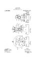
Figure- 1 shows a front view of the invention;
Fig. 2 is a transverse section taken on the line -22 of Fig. 5-, in the direction of'the Fig. 3 is a like view taken on the line 33, in the direction of the arrows, parts being omitted;
Fig. 4 is a view similar to Fig. 1, with an element in a changed position;
Fig. 5 is a longitudinal section of the previous figure taken on the line 55 in the direction of the arrows;
Fig. 6 is an enlarged partial plan view of a degree scale and coacting Vernier, used in conjunction with the device; and
Fig. 7 is a similar view of a modified form of the scale and Vernier.
In these views the numeral 11 denotes a base from which extend uprights 12, 13, and the latter as well as said base may be hollow as shown. In the preferred construe ti'on, these uprights are set back inwardly from the front and rear edges of the. base. being connected therewith by inclined walls which form an open space or clearance outside of the said uprights, the purpose whereof will be more fully hereinafter referred to. The longitudinal sides of the said base project outwardly of the uprights and afford ledges 18, 19 adapted to receive the ends of clamps (not shown) by means of which the base can be held to a primary support, such as a surface plate for instance. To this end the underside of the base 11 is machined or finished to a plane and even bearing surface. On the inside, the said base may be provided with ribs 21, 22 spaced a certain distance away from and parallel with the longitudinal walls thereof. Paired slotted openings 23, 24 are disposed through the tops of the ledges 18 and 19 outsideof the uprights between the said walls and I'lbS 21, 22, which slots are designed to take over the ends of bolts (not shown) enterlng the primary support, where the construction admits of using such fastening means.
At their upper ends the uprights 12, 13
plate located right angularly with relation to the axis of the spindle. The inner end 36 of the said carrier plate is shouldered and abuts against the outside portion 32 of the bearing 29, and a collar 37 fixed to the rear of the spindle 31 adjacent the bearing 30 maintains the said-spindle and the therewith rotatable carrier 35 in axial almement. Va-
rious means may be employed for holding a piece of work such as a casting, forging or other object to the carrier 35. The instrumentalities shown consist of groups of elon gated apertures 38 radially disposed at different distances from the center of the spindle 31, which latter, if preferred, may be made hollow. A clamp strap or bridge 39 is pulled up against and holds the work to the face plate 35, as for instance, by means of a bolt 40 passing through one of the apertures 38, with its head bearing on the inner side of the said face plate. To give the latter sufiicient rigidity an annular flange 41 is formed circumferentially therearound,
which flange is provided with graduations 42 in the are of a circle.
An index arm 47 forming part of the outer sleeve 33, that is loosely mounted on the bearing extension 32, coacts at its outer end 48 with the graduations 42 on the periphery of the work carrier which it overlies. The said end 48 is broadened in the nature of a Vernier with graduations 49 thereon. Two exemplifications of coacting circular scales and verniers are shown in Figs. 6 and 7. In the former figure, is illustrated how the graduations on the edge of the carrier 35 denote every degree of the circle, while the distance of five degrees on the Vernier is divided into 'six equal parts of 10 minutes bc tween each. In other words. each of said parts is. equal to one degree less one sixth thereof. Thus for example, if the one degree mark, below the zero on the scale, be moved to the ten mark, that is between and on the Vernier, the carrier has been given an angular adjustment of 10 minutes. Like- 9 mark to :30 min.; 4th to :40 min.;
5th to 50:50 min.; and obviously, if the sixth degree mark on the scale is moved to the division on the vernier, 60 minutes or a' full degree isregistered. Where the character of the work is such that it does not require the accuracy attainable with the aforesaid arrangement, it may suflice to I mark the carrier edge with only a scale of every fifth degree as represented in Fig. 7 and to divide the same distance on the vernier in five equal parts of one degree each.
Whereof follows, that every advance of a graduation on the scale to one of the Vernier,
produces an adjustment of one degree, and
the fractions of a degree, such as l, land so on, are left to the operators estimation or judgment in setting the carrier or face )late.
he index arm 47 is held in a pre etermined position on the bearing extension 32 by means of the before mentioned sleeve 34, the hub of which is split and clamped to the said extension bya bolt 50. One end of the latter is threaded into one of a pair of ears 51, provided on the said split sleeve 34, and bears with its shoulder 52 against the other car thereof, while a comparatively long shank 53 of the bolt projects with its 0 erating head 54 sufficiently outward to a 0rd a convenient mani ulating grip. A pair of arms 55, 56 spaced in parallelism apart extend out from the sleeve hub 34 substantially opposite to the clamping means thereof. A headed screw 57 having threaded engagement with the outer end of the arm 55 bears with its other end against an ear 58 rearwardly offset from theindex arm 47. By the adjustment of this screw the graduations on the Vernier head 42 of the said arm 47 may be brought in register with the graduations on the circumferential edge of the carrier plate 35. Although the means for holding the arm 47 up against the ad j usting screw 57 has been shown as consisting of a similar screw 59 threaded into the corresponding arm 56 it is understood that any other element accomplishing the same purpose could be used as well.
To hold the spindle 31 and the therewith connected work carrying plate 35 fixedly in their assigned position, a split hub 64 is arranged to grip around the said spindle. As represented, this latter clamping hub is placed adjacent to the inner face of the front bearing 29, but it is obvious that it could be located elsewhere on the spindle. A bolt 65 with a handle portion 66 within convenient reach of the operator, has its threaded end engaging one of a pair of cars Substantially diametrically opposite these mace:
ears extends an arm- 69,-hnvingits inner portion widenai'and slitted to afford increased resiliency to the said hub 64 when the clampescrew- 65 is tightened. The outer end of.t arm 69 is received between the inner ends of adjusting screws 71, 72. In Figs. 3 and 5 is represented how these screws have threaded engagement with lugs 73,. 74 respectively, formed with=the inner surface of the front 11 right 12, but it isreadily perceived'that t c said screws can be 0 ratively maintained in any other part 0- the structure.
At the rear end the said spindle 31 is provided with screw threads 75 adapted to receivethe threaded hub of a-chuck such as is used for example on a lathe. ere, the edge of the face plate fills the function of a graduated dial. a
The operation of thedevice is more readily understood in conjunction withthe description of how a certain 'ece of work, for
instance, an angle or bel crank lever A,
shown by dotted lines in Figs. 1 and 4:, is
laid out. The apparatus in its entirety is' placed on and secured to a surface plate, which may be either of the bench or fioor variety depending upon the size of the work to be handled. The operator, first, clamps and locks the spindle 31 with the work carrier 35 firmly in position by means of the bolt 65 and adjusting screws 71, 72. Secondly, he fastens the work, to the face of the carrying plate 35 as by means of a strap and bolt, as shown. After havmg chalked or otherwise prepared the surface of the bosses b, c and d of the lever A, he places a sur face gage preferably on the same surface plate upon which the base of "the devlce stands, and adjusts the scratching point of the gage until it comes approximately even with the center of the bosses b and 0. If the latter should happen to be out of level which is usually the case at first, the operator can easily rectify this, by loosening one.
and tightening the other, of the before mentioned adjusting screws 71, 72, until the correct alinement is secured. Thirdly, after he has located these bosses and the scratching point of the gage in correct location one relatively to the other, the operator proceeds to scribe a line 0 on the said bosses. Fourthly, he measures on a scale 'or rule the .distance at which the center of the upper boss (1 should be placed from the line e, sets the scratching point of the surface gage to this dimension, and lays off or scribes the upper line 7 parallel to e. F ifthly, the operator locates the Vernier head 48 in register with some certain graduation on the circular scale 42 of the work carrier, it not being necessary to select zeroevery time, since any given graduation may be chosen to start from. This adjustment is first tried roughly by fixing the sleeve 34 by means of the clamp bolt '50 'on' the bearing extension'.-32, the final adjustment being obtained by the screws 5 59. If in starting, two outside or extreme lines on the vernier are made to stand in correct correlation with a pair of gradnations on the edge of the plate 35, it will contribute to accuracy in positioning these elements. Sixthly, the next step taken by the operator on the particular piece of work operated upon, is to turn the work carried or one right angle around, this being accomplished by loosening the clam hu 64, rotating the carrier with the work thereon the required amount, tightening the bolt. 65, and effecting the final settin by means of the adjustment screws 71, 72. Ihis latter position is illustrated by Fig. 4. Seventlily the operator proceeds to lay out the cross lines 9 k and i in the same manner as before described with regard to the-lines e and f. The work piece is next removed from the carrier, and the intersections between the various lines marked with a prick punch. The work is now ready to be placed under the drill press to have the desired size of holes bored therein and the bosses faced if necessary. Should it be required to lay out other angles besides the one mentioned, it is obvious that the same procedure is followed, and if it should be found necessary to lay out different angles in succession on a certain piece of work, this is readily accomplished by first moving the edge scale of the carrier to the vernier, next, changing the vernierto the new angle, then the carrier to the new angle also, and so on, until all the an les one after the other have been laid out. Vernier arm 47 with its adjusting screws is indicated by dotted lines at J Fig. 2. The clearance or open space between the inwardly ofi'set front upright 12 and the rear edge of the work carrier is especially advantageous when the index arm stands below the bearing or the sleeves, as it gives the operator free and easy access to adjust the screws 57, 59.
Although the lines laid out on the work piece illustrated in Figs. 1 and 4, extend in the same plane as the work-carrier, it is obvious that lines can be scribed perpendicularly against the latter, should the nature of the work require it. Furthermore, by guiding the surface gage on the face of the work carrier, the operator may lay out other lines intersecting those last named at a right angle.
Should the occasion require the use of a chuck at the end of the spindle 31, it is self evident that the manipulation of the device is precisely the same as before, the face plate with the edge graduation thereon serving as an indexing dial.
While certain preferred embodiments of this device has been shown and described, it
different or changed position of the right angles to the axis of rotation, indexing means coacting with said carrier, and other means coaxial with said indexing means and the carrier for'clamping the latter with the work and adjustable angularly relatively to j the first mentioned means.
' depen 3. A laying-out device, comprising a rotatable carrier adapted to hold work in a predetermined position, indexing means codperatin with said carrier and adjustable inently thereof, and other means for clamping the work holding carrier, said other means being capable of adjustment together with the tter relatively to. said indexing means and also apart from the said carrier.
4. A laying-out device, comprising a revoluble carrier bearing graduations and adapted to retain work relatively fixed thereon, indexing means rotatively adjustable with relation to said graduations, and means for clamping the work holding carrier in a predetermined position independently of said indexing means.
5. A laying-out device, comprising a rotatable carrier adapted to hold workin a relatively fixed position, said carrier having peripheral graduations, an index mounted concentrically with the axis of said carrier cooperating with the graduations on the latter, means for adjusting said index, clamping means for holding the carrier independently of the index, and other means for setting the carrier with relation to the index.
6. A laying-out device, comprising a rotatable work carrier 'havin circumferential graduations, a rotatably a justable arm ex tending radially of the axis of said carrier, and a vernier projecting from said arm over said graduations.
7. 'A laying-out device, comprising a rotatable work carrier with graduations on the periphery thereof, a radial arm revolubly mounted in rear of said carrier, a Vernier on said arm overlying the periphery of the carrier co-actinfg and means or adjusting the arm with the Vernier independently of the said carrier.
8. A laying-out device, comprising 2. revwith the graduations thereon,
dl'iilil'e w'i'ark'carrier, a clampin arm coaxial with said carrier and rotatab e independently thereof cooperating with the carrier,- an index arm e06 ating with the carrier mounted loosely with relation to the latter to register its setting, and means for adjusting said arms relatively to each other.
9. A laying-out device, comprising a revoluble work carrier, an arm capable of being clamped concentrically with said carrier at a predetermined part thereof, an index am located adjacent said named arm and adapted to register the setting of the carrier, means for adjusting said index arm with relation to the other arm, and other means for holding the index arm against said adjusting means. v
10. A laying-out device, comprisin a 1'0- tatable work carrier, a sleeve mounted oosel around the axis thereof, an index arm extend ing from said sleeve to the periphery of said carrier in position to indicate various settings thereof, a clamping sleeve adjacent to said first named sleeve and capable of adjustment independently of the carrier, an arm' projecting from said clamping sleeve in proximity to said index arm, and interconnecting means whereby the index arm may be set with relation to the clamping arm.
11. A laying-out device, comprising a rotatable work carrier, means for holding said carrier in a relatively fixed position, and other means for adjusting said holding means and thereby securing further adjustment for the carrier in the same plane.
12. A laying-out device,-comprising a. rotatable work carrier, means for holding said carrier in a relatively fixed position, and other means for imparting additional angular adjustment to the carrier in the same plane of rotation.
13. A laying-out device, comprising a rotatable work carrier, a support therefor, means for gripping said carrier, and other means for adjusting said gripping means relatively to said support to effect additional adjustment of the carrier in the same plane.
14. A laying-out device, comprising a rotatable work carrier, a support therefor, means for holding said carrier in a predetermined plane, and other means connected with said support adapted to act upon said holding means to effect further adjustment of the carrier in the said plane.
15. A laying-out device, comprising a rotatable work carrier, a support for the same, retaining means for said carrier, and other means including parts acting in opposition to each other whereby adjustment of said retaining means and the carrier is effected.
16. A laying-out device, comprising a ro tatable work carrier, a support for said carrier, clamping means for holding the latter relatively fixed, an arm extending from said clamping means,'and other means with said support acting upon said arm for eifecting angular adjustment of the carrier in. its original plane of rotation.
17 A laying-out device, comprising a rotatable work carrier, a support therefor, clamping means for holding said carrier relatively fixed, an arm depending from said clamping means, and other means carried by said support acting on opposite sides of said arm so as to efiect rotary adjustment of the carrierwith relation to its said support.
20. A laying-out device, comprising a rotatable work carrier having a spindle, a support with bearings for said spindle, one of said bearings having an extension, an index adapted to indicate the setting of said carrier and capable of being rotatably held in various adjustments in said extension, and combined means for clamping and angularly adjusting the spindle and carrier.
21. A laying-out device, comprising a support, a work carrier provided with circumferential graduations and having a shank 'journaled in said support, one end of said shank extending beyond the bearing thereof, an index coacting with said graduations, means for holding said carrier in relatively fixed position and capable of subsequent adjustment therewith, and means for attaching a secondary carrier to the extended end of the shank enabling the former to partake of said adjustment in conformity with the indexing of the first named carrier.
22. A laying-out device, comprising a support, a spindle journaled therein, a face plate at one end of said spindle provided with graduations, the other end of the spin dle being threaded to receive a work hold-- ing element, means for maintaining said spindle in a relativclyfixed position and capable of subsequent adjustment therewith, and an index cooperating with said graduations available to locate work held by said element. v
23. A laying-out device, comprising a support including a bearing provided with concentric outer portion, a graduated face plate having a spindle journaled in said bearing, a loose sleeve and a clamp sleeve rotatably mounted on said concentric portion, an index on said loose sleeve adapted to coact with the graduations of said plate, arms extending from said clamp sleeve on opposite sides of said index, and screws threaded into said arms in position to effect adjustment of the index with relation to said graduations.
24. A laying-out device' comprising a support including a bearing, a graduated face plate having a spindle journaled in the latter, an index mounted on said support and adapted to coact with the graduation's on said plate, a split hub around said spindle arranged to grip the same by clamping, an arm projecting from said hub, and screws threaded into the support on opposite sides of said arm in position to effect adjustment of said spindle and face plate.
25. A laying-out device comprising a support, a graduated face plate having a spindle journaled in said support, aplurality of sleeves disposed one after another along saidspindle, a pair of said sleeves be ing rotatably sustained concentrically with the spindle, the first one in the pair includ-' ing an index adapted to coact with the graduations on said plate, and the other sleeve in said pair controlling the adjustment of the first, a third sleeve mounted directly on the spindle and capable of holding it by clamping, and means for eifecting angular variation of said third sleeve whereby a similar interrelative movement is produced between the graduations on the, face plate and said index.
Signed at the borough of Manhattan, in the county of New York and State of New York, this 23rd day of December, A. D. 1914:.
JOHN D. WEBBER. Witnesses:
H. C. KARLSON, W. H. GEE.
Priority Applications (1)
| Application Number | Priority Date | Filing Date | Title |
|---|---|---|---|
| US87916014A US1237001A (en) | 1914-12-26 | 1914-12-26 | Laying-out device. |
Applications Claiming Priority (1)
| Application Number | Priority Date | Filing Date | Title |
|---|---|---|---|
| US87916014A US1237001A (en) | 1914-12-26 | 1914-12-26 | Laying-out device. |
Publications (1)
| Publication Number | Publication Date |
|---|---|
| US1237001A true US1237001A (en) | 1917-08-14 |
Family
ID=3304820
Family Applications (1)
| Application Number | Title | Priority Date | Filing Date |
|---|---|---|---|
| US87916014A Expired - Lifetime US1237001A (en) | 1914-12-26 | 1914-12-26 | Laying-out device. |
Country Status (1)
| Country | Link |
|---|---|
| US (1) | US1237001A (en) |
Cited By (5)
| Publication number | Priority date | Publication date | Assignee | Title |
|---|---|---|---|---|
| US2482051A (en) * | 1945-04-16 | 1949-09-13 | Ralph S Yingling | Rotary checking fixture |
| US2583408A (en) * | 1945-10-30 | 1952-01-22 | Black Leon Paul | Sine-bar grinding wheel truing device |
| US2651845A (en) * | 1948-02-18 | 1953-09-15 | Timken Roller Bearing Co | Roundness checking gauge |
| US2896330A (en) * | 1957-01-23 | 1959-07-28 | Daniel R Powell | Rotary checking fixture |
| US3352019A (en) * | 1964-07-22 | 1967-11-14 | Peerless Aluminum Foundry Co I | Layout fixture |
-
1914
- 1914-12-26 US US87916014A patent/US1237001A/en not_active Expired - Lifetime
Cited By (5)
| Publication number | Priority date | Publication date | Assignee | Title |
|---|---|---|---|---|
| US2482051A (en) * | 1945-04-16 | 1949-09-13 | Ralph S Yingling | Rotary checking fixture |
| US2583408A (en) * | 1945-10-30 | 1952-01-22 | Black Leon Paul | Sine-bar grinding wheel truing device |
| US2651845A (en) * | 1948-02-18 | 1953-09-15 | Timken Roller Bearing Co | Roundness checking gauge |
| US2896330A (en) * | 1957-01-23 | 1959-07-28 | Daniel R Powell | Rotary checking fixture |
| US3352019A (en) * | 1964-07-22 | 1967-11-14 | Peerless Aluminum Foundry Co I | Layout fixture |
Similar Documents
| Publication | Publication Date | Title |
|---|---|---|
| US2369425A (en) | Work holder and indexing means | |
| US1981174A (en) | Tool grinder | |
| US1237001A (en) | Laying-out device. | |
| US3380322A (en) | Angular work indexing table | |
| US3991478A (en) | Mechanism for locating an object | |
| US4320581A (en) | Leveling | |
| US2610552A (en) | Rotary table | |
| CN204295346U (en) | A kind of chuck table | |
| US2164455A (en) | Shaft indexing device | |
| GB1008097A (en) | Attachment for use on grinding machines | |
| US1953614A (en) | Indicating device | |
| CN205996565U (en) | A kind of axle multi-angle keyseat regular worker's harness | |
| US2336163A (en) | Indicator | |
| US3664030A (en) | Apparatus for making rotary cutting dies | |
| US2508730A (en) | Regular and irregular shapes cutting machine | |
| US3704684A (en) | Attachment for measuring coordinates in a milling machine | |
| US4133231A (en) | Lathe turning fixture | |
| US2391317A (en) | Grinding fixture | |
| US2633763A (en) | Angle drilling and tapping device | |
| US3086426A (en) | Angularly and rectilinearly adjustable tool carrier | |
| US2842905A (en) | Work holder | |
| US2438813A (en) | Engraving apparatus | |
| US2703032A (en) | Radius tool | |
| CN107530896B (en) | Electric tool | |
| US1453067A (en) | Universal taper protractor |