US123647A - Improvement in looms - Google Patents
Improvement in looms Download PDFInfo
- Publication number
- US123647A US123647A US123647DA US123647A US 123647 A US123647 A US 123647A US 123647D A US123647D A US 123647DA US 123647 A US123647 A US 123647A
- Authority
- US
- United States
- Prior art keywords
- shuttle
- binder
- plate
- looms
- over
- Prior art date
- Legal status (The legal status is an assumption and is not a legal conclusion. Google has not performed a legal analysis and makes no representation as to the accuracy of the status listed.)
- Expired - Lifetime
Links
- 239000011230 binding agent Substances 0.000 description 7
- 239000004744 fabric Substances 0.000 description 3
- 238000009941 weaving Methods 0.000 description 2
- 238000010276 construction Methods 0.000 description 1
- 230000000694 effects Effects 0.000 description 1
- 239000002184 metal Substances 0.000 description 1
- 230000000284 resting effect Effects 0.000 description 1
Images

Classifications
-
- D—TEXTILES; PAPER
- D03—WEAVING
- D03D—WOVEN FABRICS; METHODS OF WEAVING; LOOMS
- D03D49/00—Details or constructional features not specially adapted for looms of a particular type
- D03D49/60—Construction or operation of slay
Definitions
- the invention also consists in a binder'plate, (one at each end of the lathe,) upon which the shuttle-flange or hook slides, this binder resting upon a suitable spring, and there being over it a lip or flange projecting from a stationary guard-plate fixed to the back of the lathe.
- the invention also consists in combining with the binder-plates and in front of the reed-dents vertical pins projecting from I race.
- each pin standing in front of one of thereed dents. These pins serve as a guide to the shuttle in its movements, keeping it in a straight path.
- the shuttle is made with a cop-containingmetal shell or case, k, which is of a hollow form, and receives the cop I, said cop being held in place by the strap m, but permitting the yarn to render freely from the shuttle.
- Each binder-plate t is a vertical plate, pivoted at m, and rests at its outer end on a spring, n, which spring is made adjustable in position by means of a setscrew, q.
- each binderplate Over the top edge of each binderplate is an overhanging lip, 0, extending from a stationary guard-plate, p, fixed to the back of the lathe, and between this lip and the upper edge of the hinder the flange w of the shuttle passes, and is caught at each completion of movement of the shuttle, the shuttle-flange binding between the two, and the shuttle being gradually arrested by the friction between them, and the friction being made greater or less by adjusting the spring a.
- a series of short pins, 'r extends up from therace a and placed in front of dents b of the lathe so as not to interfere with the free passage of the warp-yarns. Over these pins the shuttle-flange slides, the pins Claims.
- the shuttle made with the cop-receiving shell and with a sliding shoe or shoe-plate, substantially as shown and described.
Landscapes
- Engineering & Computer Science (AREA)
- Textile Engineering (AREA)
- Looms (AREA)
Description
JOSEPHSMIITH & P.'McM.AHON;
Improvementv in Looms.
Patented Feb. 13, I872.
m murmur/warren): m M r. asses/1:3- morn-s.)
UNITED STATES PATENT OFFICE.
JOSEPH SMITH, OF SOMERVILLE, AND PHILIP MCMAHON, OF OHARLESTOWN,
ASSIGNORS TO JOSEPH SMITH, OF SOMERVILLE, AND HENRY W. JACK- SON, OF BOSTON, MASSACHUSETTS.
IMPROVEMENT IN LOOMS.
Specification forming part of Letters Patent No. 123,647, dated February 13, 1872.
- provements in Looms for Weaving Gunny- Cloth; and we do hereby declare that the following, taken in connection with the drawing which accompanies and forms part of this specification, is a description of our invention suflicient to enable those skilled in the art to practice it.
Our invention relates particularly to certain details of construction of looms for weaving gunny-cloth, burlap, and similar heavy coarse goods, the improvements being designed to effect more perfectly movements and stoppage of the shuttle, and thereby produce better cloth. To produce the desired results we employ a peculiar shuttle-race'or track and a peculiar shuttle-binder mechanism and our invention consists, first, irhashuttle having no spindle, but having the yarn wound in a cop-shaped coil contained in a shell, (having somewhat the form of a boat in miniature, the cop of yarn being held down by an elastic strap or other device, which, while holding the cop in position, allows the yarn to freely render from it,) this shell being fixed to or forming part of a plate or shoe, which runs over the race, (it
having beneath it a runner that glides over wires or projections which make up the raceway,) said plate or shoe having upon one side a grooved or hook-shaped piece or flange, which, when the shuttle is at either end of the race, slides over and rests upon a binder-pl ate. The invention also consists in a binder'plate, (one at each end of the lathe,) upon which the shuttle-flange or hook slides, this binder resting upon a suitable spring, and there being over it a lip or flange projecting from a stationary guard-plate fixed to the back of the lathe. Between the lip and the top edge of the binder the shuttle-flange slides, and the position of the binder and overhanging plate and the'upward pressure upon the binder-plates are such that the motion of the shuttle is gradually stopped. The invention also consists in combining with the binder-plates and in front of the reed-dents vertical pins projecting from I race.
the top of the race, and placed in the plane of and between the ends of the two bind plates,
each pin standing in front of one of thereed dents. These pins serve as a guide to the shuttle in its movements, keeping it in a straight path.
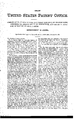
The drawing represents the top of a lathe embodying our improvements. A is a front view of the race and shuttle. B is a plan of them. 0 is an end view. D shows one of the binder-plates and its pivot and spring. E is a cross-section of the binder and adjacent parts.
a denotes the top of the shuttle-race; b, the dents through which the warp-yarns run, and in which the shed is opened for flight of the shuttle. e denotes the metal shuttle. Said shuttle has a bottom plate or shoe, f, under which is a runner or rib, g, which rests upon and slides over a series of track-wires, h, the runner g and wires h insuring a minimum of friction as the shuttle flies over the shuttle- At the inner edge of the shoe the shoeplate bends so as to form a sort of a hook, which, when the shuttle is at rest or is approaching the end of its flight, rests upon or rides over the top of a binder-plate, i. The shuttle is made with a cop-containingmetal shell or case, k, which is of a hollow form, and receives the cop I, said cop being held in place by the strap m, but permitting the yarn to render freely from the shuttle. Each binder-plate t is a vertical plate, pivoted at m, and rests at its outer end on a spring, n, which spring is made adjustable in position by means of a setscrew, q. Over the top edge of each binderplate is an overhanging lip, 0, extending from a stationary guard-plate, p, fixed to the back of the lathe, and between this lip and the upper edge of the hinder the flange w of the shuttle passes, and is caught at each completion of movement of the shuttle, the shuttle-flange binding between the two, and the shuttle being gradually arrested by the friction between them, and the friction being made greater or less by adjusting the spring a. In line with the binder-plates a series of short pins, 'r, extends up from therace a and placed in front of dents b of the lathe so as not to interfere with the free passage of the warp-yarns. Over these pins the shuttle-flange slides, the pins Claims.
1. The shuttle made with the cop-receiving shell and with a sliding shoe or shoe-plate, substantially as shown and described.
2. The shuttle made with the flange a; for
sliding upon the pins r and between the binder and lip 0, substantially as described.
3. The shuttle-shoe made with the runner g for sliding upon the track-wires h, substantially as described.
4. The binder-plates i, on the edge of which the hooked edge n of the shuttle rides, and guardlips 0 for gradually arresting the shuttle substantially as described.
5. The pins 1', over which the shuttle fiange rides, substantially as described.
6. The track or race-wires h, upon which the shuttle-shoe travels, substantially as described. JOSEPH SMITH.
PHILIP MOMAHON. Witnesses:
J. B. GRosBY, FRANCIS GOULD.
Publications (1)
| Publication Number | Publication Date |
|---|---|
| US123647A true US123647A (en) | 1872-02-13 |
Family
ID=2193082
Family Applications (1)
| Application Number | Title | Priority Date | Filing Date |
|---|---|---|---|
| US123647D Expired - Lifetime US123647A (en) | Improvement in looms |
Country Status (1)
| Country | Link |
|---|---|
| US (1) | US123647A (en) |
Cited By (1)
| Publication number | Priority date | Publication date | Assignee | Title |
|---|---|---|---|---|
| US2417285A (en) * | 1944-11-03 | 1947-03-11 | William H Baker | Race plate of looms |
-
0
- US US123647D patent/US123647A/en not_active Expired - Lifetime
Cited By (1)
| Publication number | Priority date | Publication date | Assignee | Title |
|---|---|---|---|---|
| US2417285A (en) * | 1944-11-03 | 1947-03-11 | William H Baker | Race plate of looms |
Similar Documents
| Publication | Publication Date | Title |
|---|---|---|
| US123647A (en) | Improvement in looms | |
| US31617A (en) | photo-uthcqfupheh | |
| US73063A (en) | warth | |
| US136282A (en) | Improvement in bobbins for sewing-machine shuttles | |
| US594704A (en) | Shuttle-box for looms | |
| US1729551A (en) | Tension device for shuttles | |
| US146545A (en) | Improvement in loom shuttle-stops | |
| US1084736A (en) | Thread-controlling means for sewing-machines. | |
| US77619A (en) | And george merrill | |
| US1255736A (en) | Loom. | |
| US98409A (en) | Improvement in thread-controllers for sewing-machines | |
| US382600A (en) | fielder | |
| US1180094A (en) | Protector and guide. | |
| US494108A (en) | Nathaniel lombard | |
| US22100A (en) | Braiding-machine | |
| US79579A (en) | Petejh | |
| US123094A (en) | Improvement in loom-picking mechanisms | |
| US494107A (en) | lombard | |
| US897648A (en) | Safety-regulator for braiding-machine bobbins. | |
| US124989A (en) | Improvement in stop-motions for winding-frames | |
| US418057A (en) | Shuttle for sewing-machines | |
| US677727A (en) | Shuttle for wire-weaving looms. | |
| US562598A (en) | Let-off mechanism for looms | |
| US169505A (en) | Improvement in loom-shuttles | |
| US643878A (en) | Needle-loom. |