US12355308B2 - Electric drive module having motor with heat sink insert in rotor shaft - Google Patents
Electric drive module having motor with heat sink insert in rotor shaft Download PDFInfo
- Publication number
- US12355308B2 US12355308B2 US18/386,627 US202318386627A US12355308B2 US 12355308 B2 US12355308 B2 US 12355308B2 US 202318386627 A US202318386627 A US 202318386627A US 12355308 B2 US12355308 B2 US 12355308B2
- Authority
- US
- United States
- Prior art keywords
- drive system
- motor drive
- tube
- shaft
- fins
- Prior art date
- Legal status (The legal status is an assumption and is not a legal conclusion. Google has not performed a legal analysis and makes no representation as to the accuracy of the status listed.)
- Active
Links
Images


Classifications
-
- H—ELECTRICITY
- H02—GENERATION; CONVERSION OR DISTRIBUTION OF ELECTRIC POWER
- H02K—DYNAMO-ELECTRIC MACHINES
- H02K1/00—Details of the magnetic circuit
- H02K1/06—Details of the magnetic circuit characterised by the shape, form or construction
- H02K1/22—Rotating parts of the magnetic circuit
- H02K1/27—Rotor cores with permanent magnets
- H02K1/2706—Inner rotors
- H02K1/272—Inner rotors the magnetisation axis of the magnets being perpendicular to the rotor axis
- H02K1/2726—Inner rotors the magnetisation axis of the magnets being perpendicular to the rotor axis the rotor consisting of a single magnet or two or more axially juxtaposed single magnets
- H02K1/2733—Annular magnets
-
- H—ELECTRICITY
- H02—GENERATION; CONVERSION OR DISTRIBUTION OF ELECTRIC POWER
- H02K—DYNAMO-ELECTRIC MACHINES
- H02K1/00—Details of the magnetic circuit
- H02K1/06—Details of the magnetic circuit characterised by the shape, form or construction
- H02K1/22—Rotating parts of the magnetic circuit
- H02K1/32—Rotating parts of the magnetic circuit with channels or ducts for flow of cooling medium
-
- H—ELECTRICITY
- H02—GENERATION; CONVERSION OR DISTRIBUTION OF ELECTRIC POWER
- H02K—DYNAMO-ELECTRIC MACHINES
- H02K5/00—Casings; Enclosures; Supports
- H02K5/04—Casings or enclosures characterised by the shape, form or construction thereof
- H02K5/18—Casings or enclosures characterised by the shape, form or construction thereof with ribs or fins for improving heat transfer
-
- H—ELECTRICITY
- H02—GENERATION; CONVERSION OR DISTRIBUTION OF ELECTRIC POWER
- H02K—DYNAMO-ELECTRIC MACHINES
- H02K5/00—Casings; Enclosures; Supports
- H02K5/04—Casings or enclosures characterised by the shape, form or construction thereof
- H02K5/20—Casings or enclosures characterised by the shape, form or construction thereof with channels or ducts for flow of cooling medium
- H02K5/203—Casings or enclosures characterised by the shape, form or construction thereof with channels or ducts for flow of cooling medium specially adapted for liquids, e.g. cooling jackets
-
- H—ELECTRICITY
- H02—GENERATION; CONVERSION OR DISTRIBUTION OF ELECTRIC POWER
- H02K—DYNAMO-ELECTRIC MACHINES
- H02K7/00—Arrangements for handling mechanical energy structurally associated with dynamo-electric machines, e.g. structural association with mechanical driving motors or auxiliary dynamo-electric machines
- H02K7/10—Structural association with clutches, brakes, gears, pulleys or mechanical starters
- H02K7/116—Structural association with clutches, brakes, gears, pulleys or mechanical starters with gears
-
- H—ELECTRICITY
- H02—GENERATION; CONVERSION OR DISTRIBUTION OF ELECTRIC POWER
- H02K—DYNAMO-ELECTRIC MACHINES
- H02K9/00—Arrangements for cooling or ventilating
- H02K9/19—Arrangements for cooling or ventilating for machines with closed casing and closed-circuit cooling using a liquid cooling medium, e.g. oil
-
- H—ELECTRICITY
- H02—GENERATION; CONVERSION OR DISTRIBUTION OF ELECTRIC POWER
- H02K—DYNAMO-ELECTRIC MACHINES
- H02K5/00—Casings; Enclosures; Supports
- H02K5/04—Casings or enclosures characterised by the shape, form or construction thereof
- H02K5/16—Means for supporting bearings, e.g. insulating supports or means for fitting bearings in the bearing-shields
- H02K5/173—Means for supporting bearings, e.g. insulating supports or means for fitting bearings in the bearing-shields using bearings with rolling contact, e.g. ball bearings
- H02K5/1732—Means for supporting bearings, e.g. insulating supports or means for fitting bearings in the bearing-shields using bearings with rolling contact, e.g. ball bearings radially supporting the rotary shaft at both ends of the rotor
-
- H—ELECTRICITY
- H02—GENERATION; CONVERSION OR DISTRIBUTION OF ELECTRIC POWER
- H02K—DYNAMO-ELECTRIC MACHINES
- H02K7/00—Arrangements for handling mechanical energy structurally associated with dynamo-electric machines, e.g. structural association with mechanical driving motors or auxiliary dynamo-electric machines
- H02K7/08—Structural association with bearings
- H02K7/083—Structural association with bearings radially supporting the rotary shaft at both ends of the rotor
Definitions
- the present disclosure relates to an electric drive module having a motor with a heat sink insert in a rotor shaft.
- U.S. Pat. No. 7,489,057 discloses an electric motor having a rotor with a blind hollow shaft into which a feed tube and a support member are received.
- the feed tube is disposed concentrically about along the rotational axis and includes an inlet end, which extends from the blind hollow shaft, and an outlet end that is spaced apart from a radial wall in the blind hollow shaft.
- the support member is disposed radially between the feed tube and an inside circumferential surface of the hollow shaft and extends helically about the feed tube.
- a coolant fluid is pumped into the inlet end of the feed tube as the hollow shaft rotates.
- the support member causes the coolant fluid to flow circumferentially about the feed tube as the coolant fluid travels in an axial direction back toward the inlet end of the feed tube.
- the present disclosure provides a motor drive system that includes an electric motor having a stator and a rotor assembly.
- the stator is disposed about at least a portion of the rotor assembly.
- the rotor assembly is rotatable relative to the stator about a rotational axis and has a rotor shaft, a first end wall, an insert, a coolant inlet and a coolant outlet.
- the rotor shaft has a shaft wall that is disposed about the rotational axis of the rotor assembly and defines a hollow rotor space.
- the first end wall is coupled to the rotor shaft to close an end of the hollow rotor space.
- the insert received in the hollow rotor space of the rotor shaft and has an insert body, a first flow passage and a plurality of second flow passages.
- the insert body has an outer insert surface that is engaged to an inside surface of the shaft wall.
- the first flow passage extends longitudinally through the insert body.
- Each of the second flow passages extends longitudinally through the insert body radially between the outer insert surface and the first flow passage.
- the coolant inlet is fluidly coupled to one of the first flow passage and the second flow passages.
- the coolant outlet is fluidly coupled to the other one of the first flow passage and the second flow passages.
- the present disclosure provides an insert for a hollow rotor shaft.
- the insert has a longitudinal axis and includes an insert body that defines a first flow passage, a plurality of second flow passages and a flow interruption groove.
- the insert body has an outer insert surface that is configured to be engaged to an inside surface of the hollow rotor shaft.
- the first flow passage extends longitudinally through the insert body.
- Each of the second flow passages extends longitudinally through the insert body radially between the outer insert surface and the first flow passage.
- the flow interruption groove is formed through the outer insert surface and intersects at least a portion of the second flow passages.
- the present disclosure provides a motor drive system that includes an electric motor having a stator and a rotor assembly that is received in the stator for rotation about a rotational axis.
- the rotor assembly has a rotor shaft and a coolant fluid circulating device that is received in the rotor shaft.
- the rotor shaft has a shaft wall that is disposed circumferentially about the rotational axis and which defines a hollow rotor space.
- the coolant fluid circulating device is received in the hollow rotor space and is fixedly coupled to the shaft wall.
- the coolant fluid circulating device has a first flow passage, which is disposed along the rotational axis, and a plurality of second flow passages that are disposed radially between the first flow passage and the shaft wall.
- the cooling fluid circulating device includes a central tube, a plurality of fin sets and an outer tube.
- the central tube defines the first flow passage.
- the outer tube is disposed concentrically about the central tube.
- the fin sets are fixedly coupled to an outside surface of the central tube.
- Each of the fin sets has a plurality of fin members that extend radially outwardly from the central tube.
- the fin members have a distal surface in contact with an inside surface of the outer tube.
- the outer tube has an outer surface that is in contact with a surface on the shaft wall.
- the fin members are spaced circumferentially apart from one another about the rotational axis to define a plurality of longitudinally extending slots.
- the single fin set is received into the bore in the rotor shaft such that the outer circumferential surface of the single fin set engages the inner circumferential surface of the bore in the rotor shaft.
- Each of the longitudinally extending slots is bounded on a radially outer side by the inner circumferential surface of the bore in the rotor shaft.
- the central hole forms a first fluid passage that is configured to transmit cooling fluid through the single fin set in a first direction along the rotational axis.
- the longitudinally extending slots form a plurality of second fluid passages that are configured to transmit cooling fluid through the single fin set in a second direction along the rotational axis that is opposite the first direction.
- FIG. 2 is a perspective view of an insert for a rotor of an electric motor of the motor drive system
- FIG. 3 is a sectioned perspective view of the insert
- FIG. 6 is a cross-sectional view of a portion of another motor drive system constructed in accordance with the teachings of the present disclosure
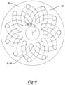
- FIG. 9 is an elevation view of a portion of the motor drive system of FIG. 7 , the view illustrating the insert body in more detail;
- FIG. 10 is a perspective view of a portion of a third motor drive system constructed in accordance with the teachings of the present disclosure, the view illustrating a rotor assembly in more detail;
- FIG. 11 is an exploded perspective view of a portion of the rotor assembly shown in FIG. 10 ;
- FIG. 12 is a longitudinal section view of the rotor assembly of FIG. 10 ;
- FIG. 13 is a section view taken along the line 13 - 13 of FIG. 10 ;
- FIG. 14 is a section view taken along the line 14 - 14 of FIG. 10 ;
- FIG. 15 is an exploded view of a portion of a fourth motor drive system constructed in accordance with the teachings of the present disclosure, the view illustrating a portion of a rotor assembly;
- FIG. 16 is an enlarged portion of FIG. 15 , illustrating a fin set in more detail.
- the motor drive system 10 can include a housing 12 , an electric motor 14 , a pump 16 , and a heat exchanger 18 .
- the housing 12 can have first and second bearing sites 30 and 32 , respectively, and can define a cavity 34 and a sump 36 .
- the electric motor 14 can be received in the cavity 34 .
- the sump 36 can be in fluid communication with the cavity 34 and can hold a predetermined quantity of an appropriate cooling fluid.
- the cooling fluid is a type of automatic transmission fluid, but it will be appreciated that other types of fluids, including water-based fluids, could be employed in the alternative.
- the electric motor 14 can be any type of electric motor, such as an AC induction motor or a permanent magnet motor, and can include a stator 40 and a rotor assembly 42 .
- the stator 40 can be fixedly mounted to the housing 12 and can be disposed circumferentially about at least a portion of the rotor assembly 42 .
- the stator 40 can define one or more stator coolant passages 46 that are formed therethrough. Each of the stator coolant passages 46 can have an outlet 48 that can discharge fluid communicated therethrough into the cavity 34 , where it can drain to the sump 36 .
- the rotor assembly 42 can be rotatable about a rotational axis 50 and can have a rotor shaft 52 , an end wall 54 , an insert 56 , a coolant inlet 58 and a coolant outlet 60 .
- the rotor shaft 52 can be supported for rotation relative to the first bearing site 30 and the second bearing site 32 via a first bearing 62 and a second bearing 64 , respectively.
- the rotor shaft 52 can have a shaft wall 70 that is disposed about the rotational axis 50 of the rotor assembly 42 and defines a hollow rotor space.
- the rotor shaft 52 is shaped as a hollow right cylinder, but it will be appreciated that the rotor shaft 52 could be shaped differently.
- the end wall 54 can be coupled to the rotor shaft 52 to close an end of the hollow rotor space.
- the end wall 54 is integrally and unitarily formed with the shaft wall 70 , but it will be appreciated that the end wall 54 could be coupled to the shaft wall 70 in a desired manner, such as press-fitting or welding.
- the insert 56 can have an insert body 80 , a first flow passage 82 and a plurality of second flow passages 84 .
- the insert 56 can be received in the hollow rotor space of the rotor shaft 52 such that the first flow passage 82 and the plurality of second flow passages 84 terminate at respective locations that are spaced apart from the end wall 54 .
- the insert body 80 can have an outer insert surface 90 that is engaged to an inside surface of the shaft wall 70 ( FIG. 1 ).
- the insert 56 is coupled to the shaft wall 70 ( FIG. 1 ) via an interference fit (e.g., press fit or shrink fit) and as such, the outer insert surface 90 directly contacts the inside surface of the shaft wall 70 ( FIG. 1 ).
- an appropriate material such as an adhesive (e.g., a thermally conductive adhesive), can be employed to fixedly couple the insert 56 to the shaft wall 70 ( FIG. 1 ).
- the first flow passage 82 can extend longitudinally through the insert body 80 .
- the first flow passage 82 is disposed along the rotational axis 50 of the rotor assembly 42 ( FIG. 1 ).
- Each of the second flow passages 84 can extend longitudinally through the insert body 80 radially between the outer insert surface 90 and the first flow passage 82 .
- each of the second flow passages 84 has a first radial end 84 a , which is disposed proximate the first flow passage 82 , and a second radial end 84 b that is disposed radially outwardly from the first radial end 84 a and proximate the outer insert surface 90 .
- the second radial end 84 b can be offset in a circumferential direction (about the rotational axis 50 ) from the first radial end 84 a in a lateral cross-section of the insert 56 that is taken perpendicular to the rotational axis 50 of the rotor assembly 42 ( FIG. 1 ).
- the second flow passages 84 can be shaped in a desired manner, such as in an arcuate manner.
- the coolant inlet 58 can be fluidly coupled the first flow passage 82 and the coolant outlet 60 can be fluidly coupled to the second flow passages 84 . It will be appreciated, however, that the coolant outlet 60 could be fluidly coupled to the first flow passage 82 and the coolant inlet 58 could be fluidly coupled to the second flow passages 84 in the alternative.
- the coolant inlet 58 is a tube that is fixedly coupled to the housing 12 , disposed coaxially with the first flow passage 82 , and projects toward the insert 56 so as to dispense fluid that flows through the coolant inlet 58 into the first flow passage 82 .
- the tube can be sized such that its inside diameter is approximately equal to the inside diameter of the first flow passage 82 and the tube can terminate near (but not touch) the insert 56 . It will be appreciated that the tube and the first flow passage 82 could be configured differently to avoid contact between the coolant inlet 58 and the insert 56 . In one alternative arrangement, a portion of the first flow passage 82 can be sized to receive (but not touch) the tube.
- the first flow passage 82 can define a counterbore (not shown) that can be larger in diameter than the outside diameter of the tube by a predetermined amount, such as 1 mm.
- the coolant outlet 60 can be formed by the open ends of the second coolant passages 84 that extend through the axial end of the insert body 80 on a side of the insert 56 proximate the coolant inlet 58 .
- the insert body 80 can optionally define a flow interruption groove 94 that is formed through the outer insert surface 90 and intersects at least a portion of the second flow passages 84 .
- the flow interruption groove 94 intersects each of the second flow passages 84 .
- the flow interruption groove 94 can be formed such that at least a portion of it has a spiral shape.
- the flow interruption groove 94 can be coupled in fluid communication to the coolant outlet 60 ( FIG. 1 ).
- an internal bore 100 can optionally be formed into an axial end of the insert body 80 that is disposed proximate the end wall 54 ( FIG. 1 ).
- the internal bore 100 can intersect the first flow passage 82 and the second flow passages 84 .
- the internal bore 100 is configured to permit the axial end of the insert 56 to be abutted directly against the end wall 54 without adversely effecting fluid communication between the first flow passage 82 and the second flow passages 84 .
- the outlet end of the first flow passage 82 can be contoured in a desired manner, such as with a fillet radius.
- the pump 16 can have a pump inlet 16 a , which can be coupled in fluid communication to the sump 36 in the housing 12 , and a pump outlet 16 b that can be coupled in fluid communication to an inlet 18 a of the heat exchanger 18 .
- the heat exchanger 18 is configured to facilitate an exchange of heat between the fluid flowing through the heat exchanger 18 and another fluid or structure, such the air that is disposed about the heat exchanger 18 .
- the heat exchanger 18 can optionally be configured to deaerate fluid that is input to the heat exchanger 18 by the pump 16 .
- An air management line 110 can fluidly couple the heat exchanger 18 to the cavity 34 in the housing 12 to permit the air that is removed from the fluid in the heat exchanger 18 to be returned to the housing 12 so that air bubbles do not circulate around the fluid loop nor create large void spaces that affect the fluid level of the sump 36 .
- Cooled fluid exiting the heat exchanger 18 through an outlet 18 b of the heat exchanger 18 can be routed back to the housing 12 .
- the cooled fluid exiting the outlet 18 b of the heat exchanger 18 is initially circulated through an auxiliary heat exchanger 120 to remove heat from an inverter 122 that supplies the electric motor 14 with electrical energy before the fluid is returned to the housing 12 .
- Cooled fluid returned to the housing 12 can be routed to the stator 40 and the rotor assembly 42 for their cooling.
- a first portion of the fluid returned to the housing 12 can be directed to cool the stator 40
- a second portion of the fluid returned to the housing 12 can be directed to cool the rotor assembly 42 .
- the portion of the coolant that is employed to cool the stator 40 can be directed into a manifold 130 that is mounted to the stator 40 . Fluid exiting the manifold 130 can be received into the stator coolant passages 46 , flow through the stator 40 and can be discharged from the stator 40 into the cavity 34 in the housing 12 where the fluid discharged from the stator 40 can collect in the sump 36 .
- the portion of the coolant that is employed to cool the rotor assembly 42 can be received by the coolant inlet 58 .
- the first coolant passage 82 is coupled in fluid communication with the coolant inlet 58 in the example provided so that fluid input to the rotor assembly 42 initially flows through the first coolant passage 82 toward the end wall 54 . Coolant exiting the first coolant passage 82 (at a location proximate the end wall 54 ) flows into the second coolant passages 84 where it is directed in an axial direction toward the coolant outlet 60 (i.e., in an axial direction away from the end wall 54 ).
- fluid can additionally flow from the (intersected) second coolant passages 84 into the flow interruption groove 94 to cause fluid flow against the inside surface of the hollow shaft wall 70 .
- the flow interruption groove 94 intersects the second coolant passages 84 at different points along the path or length of the flow interruption groove 94 to thereby break up laminar flow and possibly cause turbulence at multiple points along the path or length of the flow interruption groove 94 .
- Fluid discharged from the coolant outlet 60 can be directed to the sump 36 in the housing 12 .
- the fluid discharged from the coolant outlet 60 can be employed to lubricate a device or mechanism (not shown) that is being provided rotary power by the electric motor 14 .
- the device or mechanism could include a transmission, such as a multi-speed transmission, and/or a differential mechanism that supplies rotary power to a pair of outputs.
- fluid can be discharged from the coolant outlet 60 , the first fluid passage 82 , one or more of the second coolant passages 84 and/or the flow interruption groove 94 to lubricate the first and second bearings 62 and 64 .
- small diameter holes can be formed through the shaft wall 70 and can intersect the flow interruption groove 94 to direct pressurized fluid in the flow interruption groove 94 radially outwardly (in a spray) to lubricate the first and second bearings 62 and 64 .
- one or more holes can be formed through the shaft wall 70 to permit fluid to be discharged into a passage or cavity (not shown) formed in the housing that can direct the fluid to a desired area, such as the first and second bearings 30 and 32 .
- the coolant inlet 58 is a tube that is received coaxially within the rotor shaft 52 and is fixedly and non-rotatably coupled to the rotor shaft 52 .
- a conduit 112 that is fixedly coupled to the housing 12 is configured to transmit a pressurized coolant/lubricant, such as automatic transmission fluid, into the coolant inlet 58 .
- the coolant inlet 58 is rotatably received into the conduit 112 but spaced axially apart by a relatively small dimension. Pressurized coolant/lubricant that leaks through a radial gap 114 between the conduit 112 and the coolant inlet 58 can contact a shoulder 116 that is formed on the coolant inlet 58 .
- the shoulder 116 can be shaped to direct pressurized fluid that has leaked through the radial gap 114 between an internal aperture 118 in a gear 120 and the conduit 112 .
- the coolant/lubricant between in the internal aperture 118 can be directed by the housing 12 to an annular cavity 124 where it can flow into a bearing 130 to lubricate the bearing 130 .
- the bearing 130 supports the gear 120 for rotation about the conduit 112 relative to the housing 12 , but it will be appreciated that the bearing 130 could support another component.
- through holes could be formed through the gear 120 to permit coolant/lubricant in the internal aperture 118 in the gear 120 to be fed radially through the gear 120 to provide lubrication to the teeth of the gear 120 and/or to another component.
- the insert body 80 a is shown to be composed of a plurality of segments 150 that are fixedly coupled to one another.
- Each of the segments 150 is a circular disk that defines a first through-hole 152 and a plurality of second through-holes 154 that are disposed circumferentially about the first through-hole 152 .
- the segments 150 are stacked against one another (i.e., face-to-face) such that the first through-holes 152 form the first flow passage 82 and the second through-holes 154 form the plurality of second flow passage 84 .
- the segments 150 can be fixedly coupled to one another via any suitable means, such as brazing. Construction in this manner permits the second flow passage 84 to have any desired contouring or shape.
- the second through-holes 154 are slots that extend in a radial direction and which curve about the rotational axis 50 .
- Each of the segments 150 can be staggered about the rotational axis 50 by a predetermined amount so that the second flow passages 84 twist about the rotational axis 50 .
- adjacent segments 150 can be flipped so that the second through-holes 154 in one of the segments 150 extend in a first direction about the rotational axis 50 and the second through-holes 154 in an adjacent one of the segments extend in a second direction about the rotational axis 50 that is different from the first direction. Construction in this manner permits one of the slots in the first one of the segment 150 to be in fluid communication with two or more slots in the adjacent one of the segments 150 .
- the electric drive motor system can be substantially similar to that which is described in detail above, except for the construction of the rotor assembly 42 b .
- the rotor assembly 42 b includes an insert 56 b that is received into the rotor shaft 52 b .
- the insert 56 b can comprise a central tube 200 , a plurality of fin sets 202 , a plurality of separator plates 204 , and an outer tube 206 .
- the central tube 200 can be formed of a suitable material that can provide structural strength and can be thermally conductive, such as aluminum.
- each of the fin sets 202 can be formed of a sheet of a thermally conductive material, such as aluminum, and can be formed in a pleated manner to form longitudinal fin members 210 that are connected by inner and outer coupling sections 214 and 216 .
- each of the inner and outer coupling sections 214 and 216 is defined by a radius, but it will be appreciated that the inner and outer coupling sections 214 and 216 could be shaped somewhat differently.
- the inner coupling sections 214 and/or the outer coupling sections 216 could be formed as circular segments that interconnect adjacent fin members 210 .
- Each of the fin sets 202 is received onto the central tube 200 such that the inner coupling sections 214 touch the outside surface of the central tube 200 .
- each separator plate 204 can have a central aperture 220 and a plurality of outer apertures 222 that are disposed circumferentially about the separator plate 204 radially between the central aperture 220 and an outer circumferential surface 236 of the separator plate 204 .
- the separator plates 204 can be received onto the central tube 200 in abutment with one or more of the fin sets 202 such that the surface of the central aperture 220 contacts the outer surface of the central tube 200 and the outer apertures 220 are disposed in-line with circumferential spaces between adjacent fin members 210 .
- the circumferentially opposite sides 226 of the outer apertures 222 can be disposed in a non-parallel manner to the fin members 210 so as to cross several fin members 210 as the sides extend between their radially inner and radially outer ends.
- the outer tube 206 has an outer surface 230 , which is configured to engage/contact an inside surface 232 of the rotor shaft 52 b , and an inner surface 234 that is configured to engage the outer coupling sections 216 of the fin sets 202 and the outer circumferential surfaces 236 of the separator plates 204 .
- the outer tube 206 can be heated and/or the fin sets 202 and the separator plates 204 can be cooled prior to the assembly of the fin sets 202 and separator plates 204 into the outer tube 206 so that a resulting shrink fit between the outer tube 206 and the fin sets 202 and/or the separator plates 204 can fixedly couple the outer tube 206 to the fin sets 202 and/or the separator plates 204 .
- the fin sets 202 and/or the separator plates 204 could be bonded to the central tube 200 and/or the outer tube 206 via a thermally conductive bonding material, such as a brazing compound.
- a coolant fluid is introduced to the interior of the central tube 200 , while heat is rejected from the rotor shaft 52 b , through the outer tube 206 and into the fin sets 202 and separator plates 204 .
- the coolant fluid introduced to the central tube 200 flows out of an opposite end of the central tube 200 , and is re-directed through the outer apertures 222 in one of the separator plates 204 , into channels 240 that are formed between adjacent ones of the fin members 210 . Coolant fluid traveling through the channels 240 is directed out of the end of the insert 56 b ( FIG. 12 ) from which the coolant fluid is introduced. Fluid passing through the fin members 210 permits heat to be rejected from the fin sets 202 into the coolant fluid.
- FIGS. 15 through 17 is generally similar to the previous example except that a single fin set 202 c is employed.
- the fin set 202 c is unitarily and integrally formed from a solid material, such as compacted and sintered powdered metal, and the outer circumferential surface 300 of the fin set 202 c is engaged directly to the inside circumferential surface 232 of the rotor shaft 52 c .
- Each of the fin members 210 c can be formed via a machining operation and the outer circumferential surface 300 of the fin set 202 c can be machined in a centerless grinding operation.
- the fin members 210 c are formed via wire electro-discharge machining, but it will be appreciated that other machining processes, such as milling, grinding or sawing could be employed. It will be appreciated that the longitudinally extending slots 310 that are disposed circumferentially between adjacent fin members 210 c comprise the second flow passages 84 .
- the slots 310 are disposed circumferentially about a central hole 312 that is formed through the fin set 202 c and can be uniform in their circumferential width.
- the central hole 312 can define the first flow passage 82 .
- the fin set 202 c can be cooled and/or the rotor shaft 52 b can be heated prior to their assembly to permit the fin set 202 c to be shrunk fit to the rotor shaft 52 b .
- the slots 310 are void spaces in the fin set 202 c and can have a first volume corresponding to between 20% to 45% of a second volume of the material that forms the fin set 202 c.
Landscapes
- Engineering & Computer Science (AREA)
- Power Engineering (AREA)
- Physics & Mathematics (AREA)
- Thermal Sciences (AREA)
- Motor Or Generator Cooling System (AREA)
Abstract
Description
Claims (17)
Priority Applications (1)
| Application Number | Priority Date | Filing Date | Title |
|---|---|---|---|
| US18/386,627 US12355308B2 (en) | 2017-08-08 | 2023-11-03 | Electric drive module having motor with heat sink insert in rotor shaft |
Applications Claiming Priority (5)
| Application Number | Priority Date | Filing Date | Title |
|---|---|---|---|
| US201762542452P | 2017-08-08 | 2017-08-08 | |
| PCT/US2018/045785 WO2019032686A1 (en) | 2017-08-08 | 2018-08-08 | Electric drive module having motor with heat sink insert in rotor shaft |
| US202016751596A | 2020-01-24 | 2020-01-24 | |
| US18/115,909 US11888356B2 (en) | 2017-08-08 | 2023-03-01 | Electric drive module having motor with heat sink insert in rotor shaft |
| US18/386,627 US12355308B2 (en) | 2017-08-08 | 2023-11-03 | Electric drive module having motor with heat sink insert in rotor shaft |
Related Parent Applications (1)
| Application Number | Title | Priority Date | Filing Date |
|---|---|---|---|
| US18/115,909 Continuation US11888356B2 (en) | 2017-08-08 | 2023-03-01 | Electric drive module having motor with heat sink insert in rotor shaft |
Publications (2)
| Publication Number | Publication Date |
|---|---|
| US20240063672A1 US20240063672A1 (en) | 2024-02-22 |
| US12355308B2 true US12355308B2 (en) | 2025-07-08 |
Family
ID=65271800
Family Applications (3)
| Application Number | Title | Priority Date | Filing Date |
|---|---|---|---|
| US16/751,596 Active 2040-01-28 US11626765B2 (en) | 2017-08-08 | 2018-08-08 | Electric drive module having motor with heat sink insert in rotor shaft |
| US18/115,909 Active US11888356B2 (en) | 2017-08-08 | 2023-03-01 | Electric drive module having motor with heat sink insert in rotor shaft |
| US18/386,627 Active US12355308B2 (en) | 2017-08-08 | 2023-11-03 | Electric drive module having motor with heat sink insert in rotor shaft |
Family Applications Before (2)
| Application Number | Title | Priority Date | Filing Date |
|---|---|---|---|
| US16/751,596 Active 2040-01-28 US11626765B2 (en) | 2017-08-08 | 2018-08-08 | Electric drive module having motor with heat sink insert in rotor shaft |
| US18/115,909 Active US11888356B2 (en) | 2017-08-08 | 2023-03-01 | Electric drive module having motor with heat sink insert in rotor shaft |
Country Status (4)
| Country | Link |
|---|---|
| US (3) | US11626765B2 (en) |
| CN (2) | CN111095738B (en) |
| DE (1) | DE112018004102T5 (en) |
| WO (1) | WO2019032686A1 (en) |
Families Citing this family (22)
| Publication number | Priority date | Publication date | Assignee | Title |
|---|---|---|---|---|
| CN111095738B (en) * | 2017-08-08 | 2022-11-04 | 美国轮轴制造公司 | Electric drive module with motor with cooling insert in rotor shaft |
| DE102019100907A1 (en) * | 2019-01-15 | 2020-07-16 | Gkn Sinter Metals Engineering Gmbh | Electric motor |
| DE102019215048A1 (en) * | 2019-09-30 | 2021-04-01 | Robert Bosch Gmbh | Electric drive device for a vehicle, vehicle and method for cooling an electric drive device for a vehicle |
| CN119519263A (en) * | 2020-01-15 | 2025-02-25 | 华为数字能源技术有限公司 | Motor rotor and automobile |
| DE102021102432A1 (en) | 2021-02-03 | 2022-08-04 | Bayerische Motoren Werke Aktiengesellschaft | Modular system for a rotor shaft of an electrical machine and an electrical machine with a rotor shaft |
| WO2022191952A1 (en) * | 2021-03-11 | 2022-09-15 | American Axle & Manufacturing, Inc. | Electric drive unit with a exchanger that is formed by disks having a disk spring portion and which are received into a bore in a rotor shaft of an electric motor |
| GB202103793D0 (en) * | 2021-03-18 | 2021-05-05 | Cummins Inc | Cooling a rotating electrical machine |
| JP2022146033A (en) * | 2021-03-22 | 2022-10-05 | いすゞ自動車株式会社 | trilateral cycle system |
| DE102022204249A1 (en) * | 2021-04-30 | 2022-11-03 | Dana Tm4 Inc. | Electric axis with direct rotor and head spray cooling |
| DE102021111906A1 (en) * | 2021-05-07 | 2022-11-10 | Bayerische Motoren Werke Aktiengesellschaft | Rotor shaft arrangement for an electrical machine and electrical machine |
| DE102021114179A1 (en) * | 2021-06-01 | 2022-12-01 | Benteler Automobiltechnik Gmbh | Hollow shaft for an electric motor and method for its manufacture |
| CN114448136A (en) * | 2021-12-22 | 2022-05-06 | 华南理工大学 | Motor with multiple cooling flow channels |
| US12283875B2 (en) * | 2022-03-09 | 2025-04-22 | American Axle & Manufacturing, Inc. | Electric drive unit with rotor heat sink formed of heat sink elements |
| JP7745490B2 (en) * | 2022-03-22 | 2025-09-29 | マクセルイズミ株式会社 | power tools |
| US11519552B1 (en) | 2022-04-21 | 2022-12-06 | American Axle & Manufacturing, Inc. | Vehicle driveline component having a lubrication de-aerator |
| EP4270741A1 (en) * | 2022-04-28 | 2023-11-01 | Valeo eAutomotive Germany GmbH | Arrangement, comprising an electric motor |
| JP2024025371A (en) * | 2022-08-12 | 2024-02-26 | 本田技研工業株式会社 | Rotating electric machine system and complex power system equipped with it |
| DE102022120773A1 (en) * | 2022-08-17 | 2024-02-22 | Bayerische Motoren Werke Aktiengesellschaft | Rotor for an electrical machine, in particular a motor vehicle, and electrical machine for a motor vehicle |
| CN115489289B (en) * | 2022-08-31 | 2025-04-08 | 华为数字能源技术有限公司 | Power assembly and mechanical equipment |
| US20240333054A1 (en) * | 2023-03-27 | 2024-10-03 | Dana Automotive Systems Group, Llc | Systems for thermal management of a vehicle |
| US20250079917A1 (en) * | 2023-09-01 | 2025-03-06 | Borgwarner Inc. | Rotor having a plurality of cooling jets and electric motor including the same |
| BE1032087B1 (en) * | 2023-10-24 | 2025-05-26 | Atlas Copco Airpower Nv | ROTOR OF A PERMANENT MAGNET MOTOR FOR DRIVING AN IMPELLER OF AN AIR BLOWER |
Citations (27)
| Publication number | Priority date | Publication date | Assignee | Title |
|---|---|---|---|---|
| US3430079A (en) * | 1961-12-12 | 1969-02-25 | Westinghouse Electric Corp | Cascaded thermionic converter |
| US5703421A (en) * | 1996-05-24 | 1997-12-30 | The United States Of America As Represented By The Secretary Of The Air Force | Reluctance generator/motor cooling |
| US6191511B1 (en) | 1998-09-28 | 2001-02-20 | The Swatch Group Management Services Ag | Liquid cooled asynchronous electric machine |
| US20050047912A1 (en) | 2003-08-29 | 2005-03-03 | Giesler William L. | Fluid-cooled mechanical face seal rotor |
| US7049717B2 (en) | 2003-08-07 | 2006-05-23 | Siemens Aktiengesellschaft | Machine device having superconducting winding and thermosiphon cooling of winding |
| US20080023177A1 (en) | 2006-06-19 | 2008-01-31 | Timothy Hassett | Electric motor with heat pipes |
| EP1892511A2 (en) * | 2006-08-24 | 2008-02-27 | AVL List GmbH | Electric drive and load machine for high power test beds |
| US7489057B2 (en) | 2007-05-01 | 2009-02-10 | Tesla Motors, Inc. | Liquid cooled rotor assembly |
| WO2013004559A2 (en) * | 2011-07-07 | 2013-01-10 | Siemens Aktiengesellschaft | Electric machine with rotor interior ventilation |
| GB2501952A (en) | 2012-10-09 | 2013-11-13 | Integral Powertrain Ltd | Cooling of a motor or generator rotor magnet |
| US8704414B2 (en) | 2011-09-14 | 2014-04-22 | General Electric Company | Machines and methods and assembly for same |
| US20140368064A1 (en) | 2013-06-13 | 2014-12-18 | Tesla Motors, Inc. | Rotor Assembly with Heat Pipe Cooling System |
| US8970074B2 (en) | 2010-11-01 | 2015-03-03 | Mission Motor Company | Electric motor and method of cooling |
| US9083214B2 (en) | 2012-03-29 | 2015-07-14 | Sumitomo Heavy Industries, Ltd. | Motor |
| KR20160057017A (en) | 2014-11-12 | 2016-05-23 | 주식회사 포스코 | Cooling module and Motor having the same |
| DE102015204721A1 (en) | 2015-03-16 | 2016-09-22 | Robert Bosch Gmbh | Fluid cooled rotor for electrical machine and manufacturing process therefor |
| DE102015214309A1 (en) | 2015-07-29 | 2017-02-02 | Bayerische Motoren Werke Aktiengesellschaft | Hollow shaft cooling for driving an electric vehicle |
| CN106887914A (en) | 2015-11-23 | 2017-06-23 | 西门子公司 | Motor with cooled armature spindle |
| DE102016202416A1 (en) | 2016-02-17 | 2017-08-17 | Hirschvogel Umformtechnik Gmbh | Rotor shaft arrangement and method for its production |
| US9787164B2 (en) | 2012-03-08 | 2017-10-10 | Siemens Aktiengesellschaft | Electrical machine having a rotor for cooling the electrical machine |
| JP6225730B2 (en) | 2014-01-31 | 2017-11-08 | 株式会社豊田自動織機 | Rotating electric machine |
| GB2552678A (en) | 2016-08-02 | 2018-02-07 | Integral Powertrain Ltd | A rotary device, a motor and a method of cooling a motor |
| DE102016225523A1 (en) | 2016-12-20 | 2018-06-21 | Bayerische Motoren Werke Aktiengesellschaft | Electric machine, temperature control system and temperature control process |
| US20180191224A1 (en) | 2014-06-04 | 2018-07-05 | Thyssenkrupp Presta Teccenter Ag | Media transport in rotor shaft |
| US10033250B2 (en) | 2012-10-01 | 2018-07-24 | Abb Research, Ltd. | Electrical machine rotors |
| US20190203818A1 (en) | 2016-06-24 | 2019-07-04 | Nathan Fredrick Broker | Differential overmolded weldable ring |
| DE102018130557A1 (en) | 2018-11-30 | 2020-06-04 | Benteler Steel/Tube Gmbh | Rotor shaft for a rotor of an electric motor |
Family Cites Families (13)
| Publication number | Priority date | Publication date | Assignee | Title |
|---|---|---|---|---|
| US4182137A (en) * | 1978-01-03 | 1980-01-08 | Borg-Warner Corporation | Liquid cooling system for hermetically sealed electric motor |
| JPS6225730U (en) * | 1985-07-29 | 1987-02-17 | ||
| US6750572B2 (en) * | 2002-03-01 | 2004-06-15 | Honeywell International, Inc. | Generator with improved lubrication and cooling system |
| WO2008004286A1 (en) | 2006-07-05 | 2008-01-10 | Mitsubishi Electric Corporation | Rotating electric machine and shaft for rotating electric machine |
| JP4560067B2 (en) * | 2007-07-19 | 2010-10-13 | トヨタ自動車株式会社 | Rotating electric machine |
| US8080909B2 (en) * | 2009-05-19 | 2011-12-20 | Ford Global Technologies, Llc | Cooling system and method for an electric motor |
| WO2011163226A2 (en) * | 2010-06-21 | 2011-12-29 | Nidec Motor Corporation | Electric motor assemblies including stator and/or rotor cooling |
| US8232702B2 (en) * | 2010-07-30 | 2012-07-31 | Ge Aviation Systems, Llc | Apparatus for a high speed sleeveless rotor |
| DE102011006280A1 (en) | 2011-03-29 | 2012-10-04 | Zf Friedrichshafen Ag | Electric machine i.e. drive unit, for powertrain of hybrid vehicle, has groove-like regions arranged in contact region that is provided between rotor and rotor shaft, where groove-like regions face outer surface of rotor shaft |
| JP2013183480A (en) * | 2012-02-29 | 2013-09-12 | Toyota Motor Corp | Cooling structure of rotor for rotary electric machine and rotary electric machine |
| US9653967B2 (en) * | 2013-03-15 | 2017-05-16 | Techtronic Power Tools Technology Limited | Cooling arrangement for an electric motor |
| JP2016146704A (en) * | 2015-02-09 | 2016-08-12 | トヨタ自動車株式会社 | Rotary electric machine |
| CN111095738B (en) * | 2017-08-08 | 2022-11-04 | 美国轮轴制造公司 | Electric drive module with motor with cooling insert in rotor shaft |
-
2018
- 2018-08-08 CN CN201880058310.5A patent/CN111095738B/en active Active
- 2018-08-08 DE DE112018004102.6T patent/DE112018004102T5/en active Pending
- 2018-08-08 US US16/751,596 patent/US11626765B2/en active Active
- 2018-08-08 WO PCT/US2018/045785 patent/WO2019032686A1/en not_active Ceased
- 2018-08-08 CN CN202211273315.4A patent/CN115580055A/en active Pending
-
2023
- 2023-03-01 US US18/115,909 patent/US11888356B2/en active Active
- 2023-11-03 US US18/386,627 patent/US12355308B2/en active Active
Patent Citations (30)
| Publication number | Priority date | Publication date | Assignee | Title |
|---|---|---|---|---|
| US3430079A (en) * | 1961-12-12 | 1969-02-25 | Westinghouse Electric Corp | Cascaded thermionic converter |
| US5703421A (en) * | 1996-05-24 | 1997-12-30 | The United States Of America As Represented By The Secretary Of The Air Force | Reluctance generator/motor cooling |
| US6191511B1 (en) | 1998-09-28 | 2001-02-20 | The Swatch Group Management Services Ag | Liquid cooled asynchronous electric machine |
| US7049717B2 (en) | 2003-08-07 | 2006-05-23 | Siemens Aktiengesellschaft | Machine device having superconducting winding and thermosiphon cooling of winding |
| US20050047912A1 (en) | 2003-08-29 | 2005-03-03 | Giesler William L. | Fluid-cooled mechanical face seal rotor |
| US20080023177A1 (en) | 2006-06-19 | 2008-01-31 | Timothy Hassett | Electric motor with heat pipes |
| EP1892511A2 (en) * | 2006-08-24 | 2008-02-27 | AVL List GmbH | Electric drive and load machine for high power test beds |
| US7489057B2 (en) | 2007-05-01 | 2009-02-10 | Tesla Motors, Inc. | Liquid cooled rotor assembly |
| US7579725B2 (en) | 2007-05-01 | 2009-08-25 | Tesla Motors, Inc. | Liquid cooled rotor assembly |
| US8970074B2 (en) | 2010-11-01 | 2015-03-03 | Mission Motor Company | Electric motor and method of cooling |
| US20150069861A1 (en) | 2011-07-07 | 2015-03-12 | Siemens Aktiengesellschaft | Electric machine with rotor interior ventilation |
| WO2013004559A2 (en) * | 2011-07-07 | 2013-01-10 | Siemens Aktiengesellschaft | Electric machine with rotor interior ventilation |
| US8704414B2 (en) | 2011-09-14 | 2014-04-22 | General Electric Company | Machines and methods and assembly for same |
| US9787164B2 (en) | 2012-03-08 | 2017-10-10 | Siemens Aktiengesellschaft | Electrical machine having a rotor for cooling the electrical machine |
| US9083214B2 (en) | 2012-03-29 | 2015-07-14 | Sumitomo Heavy Industries, Ltd. | Motor |
| US10033250B2 (en) | 2012-10-01 | 2018-07-24 | Abb Research, Ltd. | Electrical machine rotors |
| GB2501952A (en) | 2012-10-09 | 2013-11-13 | Integral Powertrain Ltd | Cooling of a motor or generator rotor magnet |
| US20150288255A1 (en) | 2012-10-09 | 2015-10-08 | Integral Powertrain Ltd. | Rotary device, a motor and a method of cooling a motor |
| US20140368064A1 (en) | 2013-06-13 | 2014-12-18 | Tesla Motors, Inc. | Rotor Assembly with Heat Pipe Cooling System |
| JP6225730B2 (en) | 2014-01-31 | 2017-11-08 | 株式会社豊田自動織機 | Rotating electric machine |
| US20180191224A1 (en) | 2014-06-04 | 2018-07-05 | Thyssenkrupp Presta Teccenter Ag | Media transport in rotor shaft |
| KR20160057017A (en) | 2014-11-12 | 2016-05-23 | 주식회사 포스코 | Cooling module and Motor having the same |
| DE102015204721A1 (en) | 2015-03-16 | 2016-09-22 | Robert Bosch Gmbh | Fluid cooled rotor for electrical machine and manufacturing process therefor |
| DE102015214309A1 (en) | 2015-07-29 | 2017-02-02 | Bayerische Motoren Werke Aktiengesellschaft | Hollow shaft cooling for driving an electric vehicle |
| CN106887914A (en) | 2015-11-23 | 2017-06-23 | 西门子公司 | Motor with cooled armature spindle |
| DE102016202416A1 (en) | 2016-02-17 | 2017-08-17 | Hirschvogel Umformtechnik Gmbh | Rotor shaft arrangement and method for its production |
| US20190203818A1 (en) | 2016-06-24 | 2019-07-04 | Nathan Fredrick Broker | Differential overmolded weldable ring |
| GB2552678A (en) | 2016-08-02 | 2018-02-07 | Integral Powertrain Ltd | A rotary device, a motor and a method of cooling a motor |
| DE102016225523A1 (en) | 2016-12-20 | 2018-06-21 | Bayerische Motoren Werke Aktiengesellschaft | Electric machine, temperature control system and temperature control process |
| DE102018130557A1 (en) | 2018-11-30 | 2020-06-04 | Benteler Steel/Tube Gmbh | Rotor shaft for a rotor of an electric motor |
Non-Patent Citations (2)
| Title |
|---|
| PCT International Search Report dated Nov. 28, 2018 for corresponding PCT application No. PCT/US2018/045785, filed Aug. 8, 2018. |
| U.S. Appl. No. 18/115,909, filed Mar. 1, 2023. |
Also Published As
| Publication number | Publication date |
|---|---|
| DE112018004102T5 (en) | 2020-05-20 |
| US20200227964A1 (en) | 2020-07-16 |
| CN111095738A (en) | 2020-05-01 |
| CN115580055A (en) | 2023-01-06 |
| WO2019032686A1 (en) | 2019-02-14 |
| US20240063672A1 (en) | 2024-02-22 |
| US11626765B2 (en) | 2023-04-11 |
| US11888356B2 (en) | 2024-01-30 |
| US20230208228A1 (en) | 2023-06-29 |
| CN111095738B (en) | 2022-11-04 |
Similar Documents
| Publication | Publication Date | Title |
|---|---|---|
| US12355308B2 (en) | Electric drive module having motor with heat sink insert in rotor shaft | |
| CN108432093B (en) | Electric machine | |
| US6879069B1 (en) | Rotating machine with cooled hollow rotor bars | |
| CN111969749B (en) | Cooling assembly for an electric machine and electric machine | |
| CN104108047B (en) | A kind of electro spindle shaft core cooling system | |
| CN115224879A (en) | Rotor cooling assembly and method for permanent magnet motor interior | |
| CN115224837A (en) | Rotor assembly and method for motor end winding cooling and bearing lubrication | |
| US20220247272A1 (en) | Stator cooling structure | |
| CN115244832A (en) | Electric motor with integrated cooling system | |
| CN110022033A (en) | Coolant distributors for machine systems and corresponding machine systems | |
| CN113498572A (en) | Electric machine with internal cooling channels | |
| CN114421678A (en) | Rotor assembly, motor and vehicle | |
| CN222547262U (en) | Motor cooling structure, motor and automobile | |
| CN114123658A (en) | Oil cooling structure of driving motor and machining method thereof | |
| CN117833556A (en) | Motor and electric carrier | |
| CN113996217B (en) | High-speed dispersion machine | |
| CN218243259U (en) | Motor oil cooling system | |
| CN121014157A (en) | An electric motor system having a rotor arrangement in a fluid circuit for cooling and lubrication. | |
| CN112368468A (en) | Rotating planet carrier for a turbomachine mechanical reducer | |
| CN211117162U (en) | Composite shaft sleeve | |
| CN222515228U (en) | Drive assembly, drive system and automobile | |
| CN219945483U (en) | Cooling device of sawing machine | |
| WO2016124901A1 (en) | Liquid cooled motor | |
| WO2026096063A1 (en) | Cooling systems for e-machines having a winding arrangement | |
| CN117833557A (en) | Motors and electric vehicles |
Legal Events
| Date | Code | Title | Description |
|---|---|---|---|
| AS | Assignment |
Owner name: AMERICAN AXLE & MANUFACTURING, INC., MICHIGAN Free format text: ASSIGNMENT OF ASSIGNORS INTEREST;ASSIGNORS:RONNING, JEFFREY J.;CRECELIUS, DAVID;DOWNS, JAMES P.;AND OTHERS;SIGNING DATES FROM 20200123 TO 20200124;REEL/FRAME:065442/0629 |
|
| FEPP | Fee payment procedure |
Free format text: ENTITY STATUS SET TO UNDISCOUNTED (ORIGINAL EVENT CODE: BIG.); ENTITY STATUS OF PATENT OWNER: LARGE ENTITY |
|
| AS | Assignment |
Owner name: AMERICAN AXLE & MANUFACTURING, INC., MICHIGAN Free format text: ASSIGNMENT OF ASSIGNORS INTEREST;ASSIGNORS:RONNING, JEFFREY J.;CRECELIUS, DAVID;DOWNS, JAMES P.;AND OTHERS;SIGNING DATES FROM 20200123 TO 20230120;REEL/FRAME:065469/0395 |
|
| STPP | Information on status: patent application and granting procedure in general |
Free format text: DOCKETED NEW CASE - READY FOR EXAMINATION |
|
| STPP | Information on status: patent application and granting procedure in general |
Free format text: NON FINAL ACTION MAILED |
|
| STPP | Information on status: patent application and granting procedure in general |
Free format text: RESPONSE TO NON-FINAL OFFICE ACTION ENTERED AND FORWARDED TO EXAMINER |
|
| STPP | Information on status: patent application and granting procedure in general |
Free format text: FINAL REJECTION MAILED |
|
| STPP | Information on status: patent application and granting procedure in general |
Free format text: DOCKETED NEW CASE - READY FOR EXAMINATION |
|
| STPP | Information on status: patent application and granting procedure in general |
Free format text: NOTICE OF ALLOWANCE MAILED -- APPLICATION RECEIVED IN OFFICE OF PUBLICATIONS |
|
| AS | Assignment |
Owner name: JPMORGAN CHASE BANK, N.A., NEW YORK Free format text: SECURITY INTEREST;ASSIGNOR:AMERICAN AXLE & MANUFACTURING, INC.;REEL/FRAME:070700/0839 Effective date: 20250326 |
|
| STCF | Information on status: patent grant |
Free format text: PATENTED CASE |
|
| AS | Assignment |
Owner name: U.S. BANK TRUST COMPANY, NATIONAL ASSOCIATION, AS NOTES COLLATERAL AGENT, MICHIGAN Free format text: SECURITY INTEREST;ASSIGNORS:AMERICAN AXLE MANUFACTURING, INC.;MD INVESTORS CORPORATION;AAM NORTH AMERICA, INC.;REEL/FRAME:073005/0001 Effective date: 20251003 |